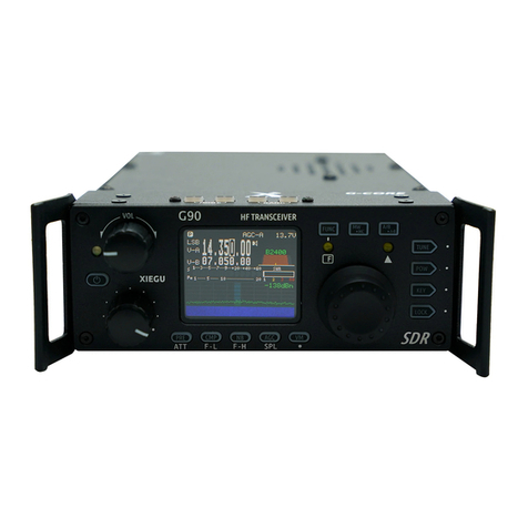
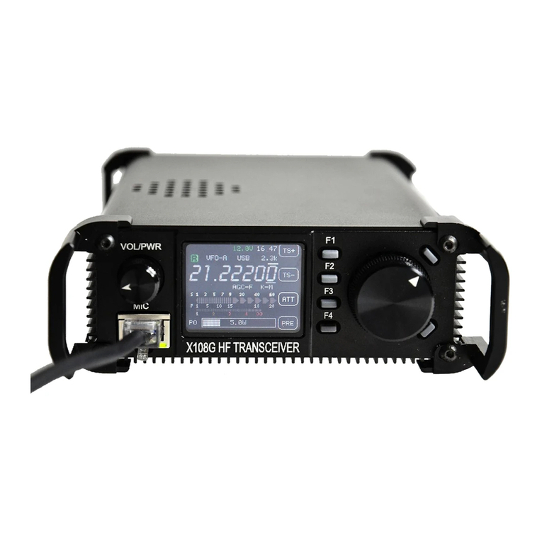
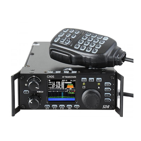
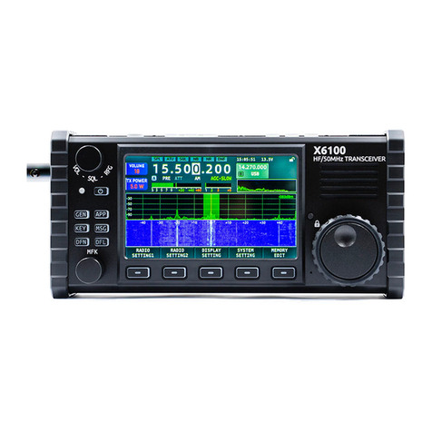
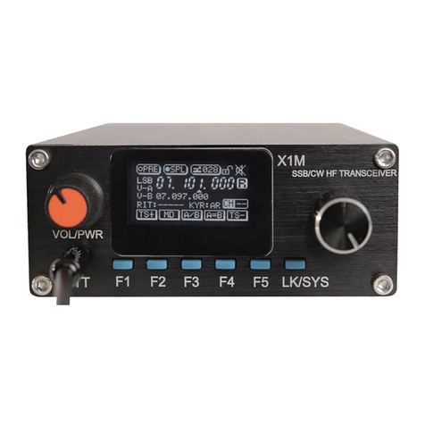
XIEGU G90 User manual

HF Transceiver
Version 4.2.1 January 2022
G90
XI
E
GU


G90 Feedback Survey: scan to share your suggesons!
Informaon on all of these and other accessories can be found at
www.radioddity.com
Thank you for purchasing a XIEGU product from Radioddity. Through a strong
partnership which allows us to bring you the latest technology from the XIEGU
In order to protect your rights please read the terms on XIEGU Warranty Card
carefully and know the Warranty Policy.
We look forward to improving our products based on
customer experience, and any ideas would be appreciated!
welcome to contact us via < support@radioddity.com >.
XPA125B
CE-19 data
interface G90-H1 fan G90-H2
stand
GSOC
controller

polarity of the power cord and do not reverse the polarity.
The warranty of this radio does not cover damage caused by an incorrect
supply voltage.
Do not tamper with the transceiver for any reason.
Do not operate the transceiver with a damaged antenna. If part of an
antenna comes into contact with your skin, a minor burn can result.
materials.
1.
2.
3.
4.
5.
6.
7.
8.
9.
10.
11.
12.
13.
14.
Do not place the transceiver over any airbag deployment area in vehicles
containing airbags.
nor place it close to any heat source.

Nagy (AB5N), Garry F. Decker, S.E.(K9WHF) and Ed Durrant (DD5LP), for their
The G90/S is an amateur radio portable 20W HF transceiver using the latest
24-bit SDR technology. It is a new member of the Xiegu product family and our
Based on a 24bit-CODEC, the G90/S brings superior transceiver performance
includes a built-in high-performance ATU capable of matching a very wide
range of antennas.
Modes provided are USB/LSB/CW/CWR/AM/NFM
1.8-inch-high-contrast color TFT LCD display
±24k bandwidth spectrum & waterfall displays
Built-in CW Decoder
Detachable head unit
Built-in Antenna SWR scanner
The G90S is the version sold in the People's Republic of China, the G90 is the
version available in other countries. This operaon manual is applicable to
both models.
can be changed. Therefore, it is recommended that you ensure your G-90/S is at
appear to work as expected on your G-90/S it is highly likely that you are at a

General Parameters
Receiver Parameters
Volume Adjustment
Call Sign Editor
............................................................................
................................................................
..........................................................
...............................................................
........................................
...................................................................
...............................................
................................................
.................................................
........................................................
.........................................................
.................................................................
..................................................................
...................................................................................
.................................
......................................................
................................................................
........................................................................
...............................................
...............................
........................
01
01
02
02
03
04
05
07
08
09
10
11
13
15
16
17
17
18
18
20
20

PRE-AMP/ATT
Pulse Interface Suppressor – Noise Blanker
Voice Compression CMP
Voice-Controlled Transmit – VOX
Standing-Wave Scanner SWR
Fine Tuning of Received Frequency (RIT)
Line Input and Output
Channel Memory Write (MW) and Clear (MC)
...........................................
.....................................
................................................
..........................................................................
...........................
........................................................
........................................
.......................................................................
........................................................
..................................................................
...............................................................
...........................................
..........................
......................................................
.................................................
................
...............................
...........................................................
.......................................................
......................
.....................................................
21
21
22
23
23
24
24
25
25
25
26
27
28
28
29
29
30
30
30
31
32

Digital (DSP) Filters
Spectrum/ Waterfall Display
Receiving
Menu Item 1: Handle up/down
Menu Item 2: Handle F1
Menu Item 3: Handle F2
Menu Item 4: LCD BL
Menu Item 5: AUX IN Volum
Menu Item 6: AUX OUT Volum
Menu Item 7: RCLK Tune
Menu Item 8: Band Stacking Mode
Menu Item 9: ON/OFF Beep
Menu Item 10: Version
.................................................................
..................................................
..............................................................
................................................................................
...........................................................................
.........................................................
..
............................................................................
..............................................
.........................................................
.........................................................
..............................................................
..................................................
...............................................
........................................................
........................................
...................................................
...........................................................
.............................................................................
.................................................
..........................................................
.....................................................................
33
34
35
35
35
36
38
39
40
40
40
40
41
41
41
41
41
41
42
42
45
45

RX
(*1)
(*1)
(*1)
(*1)
USB/LSB/CW/CWR/AM/FM*
@25°C: 1ppm/hour
Receive: 700mA@ Max
Transmit: 6A@ Max
120*45*210mm (W*H*L) (excluding protrusions)
About 1.63kg (for main body)
TX
01

20W(SSB/CW/FM)
5W (AM) @13.8VDC
Zero-IF (ZIF) direct conversion SDR
SSB/CW
/
0.35uV
0.25uV
0.25uV
AM
10uV
10uV
2uV
2uV
(Measurements made with PRE=on, ATT=off, NB=off, SSB/CW/AM=10dB S/N.)
Mirroring suppression: 70dB
Sideband suppression: 60dB
02
(*1) The operator is ALWAYS responsible to ensure he/she does not transmit
amateur without a full authority licence (i.e. entry level or novice) outside of
the allocated frequencies in their licence). Radios that are sold to service the
that are not available in some countries or under some licence classes. You
as the operator MUST ensure that you do not transmit outside of your

USB data interface cable
DB9 head unit extension cable
Hexagonal wrench
DC power cord
Warranty card
1
1
1
2
1
1
1
1
1
host ACC socket adapter (can be used as PC interface to transmit audio
external, large screen, controller.
Stand with fan
(*2)
03
(*1) The operator is ALWAYS responsible to ensure he/she does not transmit
amateur without a full authority licence (i.e. entry level or novice) outside of
the allocated frequencies in their licence). Radios that are sold to service the
that are not available in some countries or under some licence classes. You
as the operator MUST ensure that you do not transmit outside of your

MDATA
GND
MIC
MICE PTT
MSVSW
NC
MIC
TXD
RXD GND
signal
signal GND
PTT
AF_OUT
AF_IN
NC
BAND
ALC
8V DC
GND
Rear ACC socket
Le and right connecons carry
monaural audio
Di Da Common
Di Da Common
If the connector of the CW
key is a 6.5mm 2-wire plug,
please change it to a
3-connector 3.5mm stereo
plug according to the wiring
above.
Be careful when using 2-core
to 3-core adapters because
incorrect wiring may put the
radio into CW transmission
04

Turn the knob to increase or decrease the volume.
A momentary press alternates between headphone/speaker output.
radio on.
to save electricity.
05

-
7-
△
This LED blinks when the CW signal is tuned in when in CW mode allowing
the CW decoder to work.
06
bands or the Amateur and SW Broadcast bands (Transmission is only
allowed in the HAM bands). (whether the radio switches through
menu).

A 3.5mm stereo jack used to connect manual/paddle CW keys.
(See Page 04 for the wiring details)
A 3.5mm connector (3 wires) used for IQ signal output.
See the interface details on page 04.
07

of the G90/S and reduce the possibility of RF ingress.
This is a 3.5mm stereo connector (3 wires) used to connect earphones.
(See Page 04 for the wiring details).
control interface to your computer.
20
(point 22)
1. Insert the supplied 3.5mm to USB cable into this port for data transfer or
08

Press to transmit
Transmission in progress indicator light
Main keypad area
Lights whenever a key is pressed
on the microphone.
the system menu)
– e.g. preamp / split.
Frequency/memory channel
switch
No funcon
09
will switch the ATU in or out of

supply 10.5-16.5VDC and have capacity to supply up to 10 amps. Typical
current requirements on transmit are generally less than 8A. Use the provided
The DC power supply must be connected in strict accordance with the
from entering the radio via its power lines and RF interference from inside
ferrite choke place it closest to the radio end of the DC cable.
Black line
Red line
Polarity of power cables should be checked carefully to avoid reverse
power should be avoided.
10

(momentary press, cycle)
PRE - ATT - Normal. cycles
through these states.
Turn on voice compression
using the main tuning knob
Turn on the pilot
frequency transceiver
parameters
parameters
RF GAIN
Call Sign
Editor
Antenna
tuning
Clear channel entry
Copy the current VFO freq
to background VFO
NB ON-NB Level-NB Width
AGC, Fast-Slow-Auto-none
Switch between frequency
and channel mode
Write channel to memory
Switch between VFO-A
and VFO-B
(in-circuit/out-of-circuit)
Power output
POWER
SPEED
M/L/R
MODE
SWR THR
Standing-wave
Manual/
mode switching
iambic A/B
mode switching
/
/
/
/
/
/
/
MICGAIN
INPUT
CW
Volume
CW TONE
Hand microphone
Audio input
Side tone
Side tone
Standing-
wave
scanner
display
CW
decoder
11

Loudspeaker / earphone
switching
Lock / Screen brightness
Filter bandwidth mode
Open RIT
QSK
QSK Time
/
/
/
/
/ /
/
SCALE
AVE FFT
VOX
ON/OFF
VOX GAIN
ANTI-VOX
VOX DLY
Spectrum
reference level
Mean value
Voice control
switch
Voice control
transmission
Voice control
Hand microphone
and speaker echo
dot-and-dash
Insert/non-
(momentary press, cycle)
12
Other manuals for G90
10
Table of contents
Other XIEGU Transceiver manuals