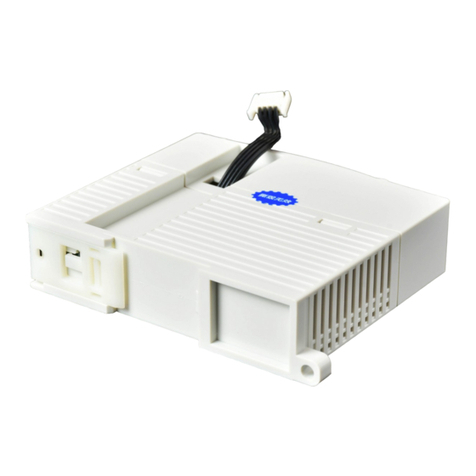
Extension ED module
XD-4DA-V-ED
Fast manual
Thanks for purchasing XINJE XD series PLC and extension module. This manual will
introduce the electric features and using method of XD series extension ED module. Please
read this manual carefully before using the products, make sure the wiring operation is safe.
Features of analog extension module
XD-4DA-V-ED
4 channels analog output: voltage output mode, 0~10V or 0~5V.
10-bit high precision analog output.
As the special function ED module of XD, XD series PLC can connect 1 XD-
4DA-V-ED module.
Safety precautions
Control system design attentions
Dangerous!
Make sure design the safety circuit, to ensure that the control system can still work
safety when the external power supply cut off or PLC broken.
Make sure set emergency braking circuit, protection circuit, interlock circuit of forward-
reverse running in PLC external circuit and upper-lower limit switch to prevent from
machine damage.
In order to make the equipment safe operation, please design external protection circuit
for important output signal.
PLC CPU will close all the output when detecting the system error; the output will lose
control when the PLC circuit has problem. Please design suitable external control circuit
to ensure the device working normally.
If the PLC relay or transistor unit is broken, the output cannot be ON or OFF.
The PLC is designed for indoor environment, the lightning protection must be installed
in the power supply system to avoid PLC and other device damage.
Installation and wiring attentions
Dangerous!
Do not use the PLC in the following environment: dust, soot, corrosive gases,
flammable gas, high temperature, condensation, vibration, impact, lightning, fire.
Do not let the metal scrap and wire head drop into the ventilation hole of PLC, otherwise
it will cause fire or error operation.
Do not cover the ventilation hole of PLC, otherwise it will cause fire, error operation.
The I/O wiring must be fixed enough, otherwise the bad contactor will cause fault.
Attention!
It can use external power supply for extension module DC24V power.
Please use shield cable for high frequency I/O wiring to avoid interference.
Run and maintenance
Dangerous!
Please connect all the cable include PLC, extension module and BD board after shutting
down the power supply.
Please operate as the manual for online operation, forced output, RUN, STOP.
Attention!
Please discard the product as industrial waste.
Make sure cut off the power supply when installing or uninstalling the extension card.
Product information
Naming rule
XD–4 DA - V - ED
①②③④⑤
①Product series XD: XD series extension module
②Analog output channel: 4: 4 channels
③Analog output DA: analog output
④I/O type V: voltage type for output
⑤Module type ED: left extension ED module
Basic parameters
XD series PLC can connect 1 extension ED module, the type is not limited.
Table 1: analog extension module XD-4DA-V-ED general specifications
Fix with M3 screw or install on the rail DIN46277(width
35mm)
的导轨上
Table 2: analog extension module XD-4DA-V-ED I/O precision
Analog voltage output (V)
0~10, 0~5V
External load resistor is 2KΩ~1MΩ
10-bit binary number (0~1023)
Table 3: analog extension module XD-4DA-V-ED AD transformation diagram
The relationship between analog output and digital input
Note: when the input data is over K1023, DA transformed analog output will keep the max
voltage.
Product appearance
Here listed I/O terminal configurations of XD series extension module XD-4DA-V-ED.
Product structure
Each part name:
The LED lights when the ED module has power supply
The LED lights when the ED module communication
port works well
The LED lights when the ED module has error
ED module external power supply 24V +
ED module external power supply 24V -
Product dimension and installation
Installation
Do not install the module in below environment:
Direct sunlight
Environment temperature out of range 0-50℃
Environment humidity out of range 35%-85% RH
Condensation as severe changes in temperature
Corrosive gas and flammable gas
Dust, iron filing, salt, fume
Vibration and impact
Spray oil, water and medicine
Strong magnetic field and strong electric field
XD series extension ED module can be installed in com3 port of XD series PLC.
Note: please cut off the power before operation!
Product dimension (Unit: mm)
XD series extension ED module dimension is shown as below:
Electric design reference
I/O address
XD series extension ED module will not occupy I/O unit, the transformed value is stored in
PLC register. The following is the PLC register corresponding to each channel.
Working mode setting
Steps:
1. open the XDPpro software, find the left project bar, click PLC config/ED.
2. choose the correct module type.
3. set the module parameters such as voltage output range.
4. click write to PLC, then re-power on the PLC to make the setting effective.
TYPE:XDM-32T4-E
DATE:20120701
SN:201207011525
Xinje Electronic Co.,Ltd
COM3


