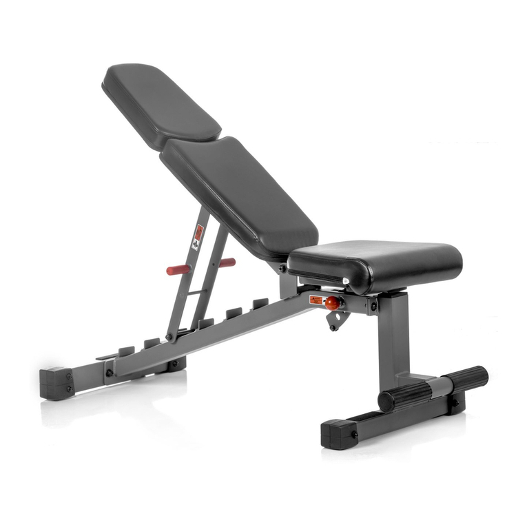
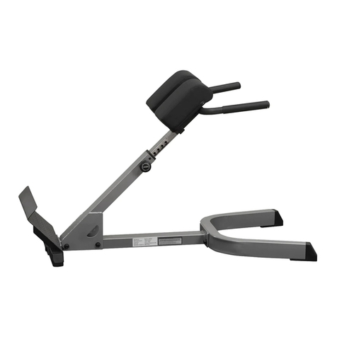
XMark Fitness XM-4424 User manual

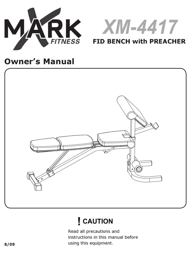
Owner’s Manual
8/09
XM-4424
Read all precautions and
instructions in this manual before
using this equipment.
INTERNATIONAL OLYMPIC
BENCH with LEG & PREACHER

2
Table of Contents
Before You Begin
Important Safety Information
Parts Identifier
Assembly
Adjustments
Attachments
Parts List
Exploded View
Warranty Information
3
4
5
6-15
16
17
19
20
22

3
MODEL: XM-4424
XM-4424
This manual will guide you through the assembly process. If at any time you
are having trouble with the assembly or use of this product, then please contact
When calling please have the following product information available:
Model Name :
Date Mfg.:
Serial #
Model Name Decal Location
Before You Start
REGISTRATION CARD
QUESTIONS?
CALL 1-800-719-4605
Monday-Friday
8:30 a.m.-5:00 p.m.
(Central Standard Time)
MAILING ADDRESS
7501 Trammel Drive
Shreveport, LA 71108
THANK YOU for making this unit a part of your exercise
program.
XMARK Fitness
assures the very best in value,
appearance, durability and biomechanics.
XMARK FITNESS SERIES
XMARK Fitness
To avoid unnecessary delays in warranty parts and to insure that a permanent
record of your purchase is on file with our company, be sure to send in the war-
ranty registration card or register online at www
.xmarkfitness.com
within 10 days
of purchase.
us at our
XMARK Fitness help line. We have trained service technicians on site to
take care of you, our valued customer.

NOTE: Hand tighten bolts and nylon nuts until machine is fully
assembled.
SAFETY PRECAUTIONS
SAFETY INFORMATION WARNING!
Prior to assembly, remove components from the box and verify that all the listed parts
were supplied.
Before using this unit or starting any exercise program, consult your physician.
This is especially important for persons over the age of 35 and/or persons with pre-
existing health problems. XMARK Fitness assumes no responsibility for personal
injury or property damage sustained by or through the use of this product.
It is the owner’s responsibility to ensure that all users of this unit have read the
Owner’s Manual and are familiar with safety information and precautions.
• This unit should only be used on a level surface and is intended for indoor use
only. XMARK Fitness recommends an equipment mat be placed under the unit to
protect the floor or carpet and for easier cleaning.
• Wear comfortable, good-quality walking or running shoes and appropriate cloth-
ing. Do not use this unit with bare feet, sandals, socks or stockings!
• Always examine your unit before using to ensure all parts are in working order.
• Do not leave children unsupervised near or on the unit.
• Service to your unit should only be performed by an authorized service represen-
tative, unless authorized and/or instructed by a XMARK Fitness technician. Failure
to follow these instructions will void the warranty.
Important Safety Information
4
5
Parts Identifier
M8 x 65mm Bolt (46)
M10 x 145mm Bolt (53)
M8 x 70mm Bolt (71)
M10 x 65mm Bolt (30)
M8 x 60mm Bolt (59)
M10 x 60mm Carriage Bolt (29)
M10 x 120mm Bolt (14)
M10 x 70mm Bolt (33)
M10 x 95mm Bolt (64)
M10 x 70mm Bolt Set (55)
Getting Started - The XMARK Fitness
XMARK Fitness
XMARK Fitness
International Bench requires some assembly. Unpack
the box in a clear area. Remove packing material. Do not dispose of packing material until
assembly is complete and unit is working properly. Place the unit on a clean level surface
for assembly. Before assembling, the unit should be placed as close as possible to its final
location. If you are missing any parts or hardware, please call at 1-800-719-
4605. Tools have been provided to assist with product assembly. recommends
that two people assemble the unit.
The included hex key, grease packet, and the following tools (not included) are recommended
for assembly.
Note: Some hardware may be pre-installed in some parts.
Hex Key (Included)
Two Adjustable Wrenches
Rubber Mallet
Flat Head Screwdriver
Phillips Head Screwdriver
M8 Washer (50)
M6 Washer (54)
M10 Washer (43)
M6 x 20mm
Bolt (41)
M6 x 40mm Bolt (48)
M10 Locknut (58)
M8 Locknut (49)
M4 x 16mm
Screw (57)
Olympic Adapter
Leg Extension
w/ Curl Bar
SafetySpotter
Weight Rest
Adjustable Tube
Arm Curl Pad
Weight Plate Holder

6
1
2
58
58
4
29
29
Recessed Areas
3
Assembly
Figure 1
NOTE:Hand tighten bolts and lock nuts until machine is fully assembled.
Step 1
Insert four M10X60mm carriage bolts (29) up through the bottom of the right stabilizer (2).
Attach the right upright (4) to the right stabilizer (2) with indicated carriage bolts and
locknuts (58).
Repeat to complete the assembly of the left stabilizer (1) and left upright (3).
Note: Make sure the recessed areas around the holes on stabilizers are on the bottom.

7
4
58
1 4
14
15
5
Step 3
Attach the right rear support (7) to the right stabilizer (2) using the indicated M10X60mm
carriage bolts (29) and two M10 lock nuts (58).
Secure the right rear support (7) to the right upright (4) using two M10X65mm bolts (30),
two M10 washers (43), and two M10 locknuts (58).
Repeat to complete the assembly for the left side (not shown).
4
29
2
30
43
58
58
58
7
Figure 2
Figure 3
Assembly
Step 2
Attach the cross bar (5) to the right upright (4) using two M10X120mm bolts (14), an upright
plate (15), and two M10 lock nuts (58).
Repeat to complete the assembly for the left upright (not shown).

8
Assembly
Step 4
Attach the front leg (12) to the front stabilizer (11) with two M10X95mm bolts (64) and two
M10 lock nuts (58).
Step 5
Position the frame (8) so that the hexagonal holes are on the bottom. Attach the frame (8)
to the crossbar (5) using three M10X70mm bolts (33), two M10 washers (43), and three M10
lock nuts (58).
58
58
43
43
5
8
Hexagonal
Holes
33
33
3 3
Figure 5
12
58
11
64
Figure 4
NOTE:Hand tighten bolts and lock nuts until machine is fully assembled.

9
Assembly
Step 6
Pull the Pop Pin (45) out as far as it will go and slide the seat carriage (42) onto the Frame (8).
Attach the front leg (12) to the frame (8) using two M8X60mm bolts (59), two M8X65mm bolts
(46), six M8 washers (50), and four M8 lock nuts (49).
Step 7
Set the pins on the adjustment tube (9) into a set of brackets located on the left and right
uprights (3 & 4).
Pin
3
4
9
Pin
42
8
49
12
59
46
49
50
50
50
50
NOTE:Hand tighten bolts and lock nuts until machine is fully assembled.
Figure 6
Figure 7

10
Assembly
Step 8
Attach the tether on the seat adjustment pin (40) to the seat frame (10) using an M4X16mm
screw (57).
Attach the seat pad (21) to the seat frame (10) with four M6X20mm screws (41).
Step 9
Attach the Upper Back Pad (22) and to the two backrest frames (17)
with eight M6X40mm screws (48) and eight M6 washers (54).
17
48
48
48
54
54
54
54
22
54
54
48
57
1 0
40
41
21
41
Figure 8
NOTE:Hand tighten bolts and lock nuts until machine is fully assembled.
Note: Do not fully tighten the screws yet.
25
Lower Back Pad
(25)

11
Assembly
NOTE:Hand tighten bolts and lock nuts until machine is fully assembled.
Step 10
Apply a small amount of grease (included) to an M10X145mm bolt (53). Attach the seat frame
(10) and the backrest frames (17) to the seat carriage (42) using the M10X145mm bolt (53),
two M10 washers (43), and an M10 lock nut (58).
Note: 1) The seat pad (21) has been removed from the drawing to clarify the installation to
the seat carriage (42). 2) Do not overtighten the nylon locknut, the seat and backrest frames
must pivot easily.
Insert the seat adjustment pin (40) through the seat frame (10) and tube located on the seat
carriage (42). Tighten the four M6X40mm screws (48) that were installed in Step 9.
42
40
53
43
Grease
T ube
58
10 43
Figure 10
Step 11
Attach the weight tube (19) to the leg lever (18) using an M8X70mm bolt (71), two M8
washers (50), a 17mmX9mm spacer (61), and a M8 lock nut (49).
Place the 25mm round outer cap (62) onto the end of the weight tube (19).
50
19
1 8
62
7 1
61
5 0
49
Figure 11
17

12
Assembly
NOTE:Hand tighten bolts and lock nuts until machine is fully assembled.
Step 12
Apply grease to the barrel of the M10X70mm bolt set (55). Next, attach the leg lever (18) to
the front leg (12) and secure using the bolt set (55). Make sure the barrel of the bolt set (55)
is inserted through both sides of the bracket on the front leg (12).
Note: Do not overtighten the bolt set; the leg lever must pivot easily.
18
12
55
Grease
Bracket
Figure 12
Step 13
Insert a Foam Roller tube (24) into either hole on the front leg (12). Slide a Foam Roller(23)
onto each end of the Foam roller Tube (24).
Insert a Foam Roller Tube (24) into a hole on the Leg lever (18). Slide a foam Roller (23) onto
each end of the Foam Roller Tube (24). Press a foam roller cap (68) into each end of the tube.
12
23
23
23
23
23
23
68
68
68
68
68
24
24
24
18

13
Assembly
NOTE:Hand tighten bolts and lock nuts until machine is fully assembled.
Step 14
Insert a weight rest (39) into the right upright (4) and secure by engaging the locking bar
around the upright.
Insert a safety spotter (27) into the right upright (4) and secure by engaging the locking bar
around the upright.
Repeat for left side.
Locking
Bar
39
4
27
Figure 14
Step 15
Attach the curl pad (20) to the curl post (13) using two M6X20mm screws (41).
2 0
13
41
Figure 15

14
Assembly
Step 16
Attach the curl bar (31) to the leg lever (18) and secure with the curl bar pin (28). Next,
attach the tether on the curl bar pin (28) to the leg lever (18) using a M4X16mm screw (57).
31
18
28 57
Figure 16
Step 17
Tighten all hardware from the previous steps using the appropriate tools.

15
Assembly
CONGRATULATIONS!
You have completed assembly of your XMARK Fitness International Olympic Bench

16
Adjustments
Seat Adjustments
To move the seat (21), loosen the Pop pin (45) and pull it out as far as it will go. Slide the
seat carriage (42) to the desired position and release the pop pin (45) back into the bench
frame (8). Retighten the Pop pin (45). See Figure A
To adjust the angle of the seat (21), remove the seat adjustment pin (40). Insert the pin into
the other hole on the seat frame (10) and the tube on the seat carriage (42). See Figure B.
21
42
45
8
Backrest Adjustment
First, move the seat pad to the desired position (see the Seat Pad Adjustment section). Next,
move the adjustment tube (9) to the desired height. Make sure the pins on the adjustment
tube are inserted into the brackets on the left and right uprights (3 & 4). Finally, rest the
backrest on the adjustment tube.
4
Pin
9
22
42
21
10 40 Tube
Figure A Figure B
73
3

17
Attachments
Curl Bar Attachment
Attach the curl bar (31) to the leg lever (18) and secure by inserting the curl bar pin (28).
Note: You will need to remove the curl bar when using the leg extension.
28
18
31
Olympic Plate Adapter
To use olympic weights, secure the olympic adapter (47) to the weight tube (19) using
M8X10mm set screw (60).
Make sure the set screw (60) is on the bottom of the adapter. Secure the weight plates with
included large spring clip (not shown).
18
12
24
19
47
60
WARNING!
Do not place more than 150 pounds on the weight tube. Secure the weights with spring clips.

18
Attachments
Arm Curl Post
Remove the 64mm square inner cap (69) from front leg (12). Insert the curl post (13) into the
front leg (12) and align the holes. Secure the curl post (13) with the curl post knob (56).
Note: Make sure that the knob is fully tightened.
When performing exercises that do not require the curl pad (20), remove the curl post (13)
and store it on the storage tube on the right stabilizer (2). Reinsert the 64mm (69) square
inner cap into the front leg.
56
20
2
69
13
Weight Rests and Safety Spotters
To use a barbell (not included) with the weight bench, first move the weight rests (39) and
safety spotters (27) to the correct height for the exercise to be performed. Engage the locking
bars around the left and right uprights.
Note: The weight rests (39) and safety spotters (27) can be inserted onto the other side of the
left and right uprights for squat exercises.
Always place both weight rests (39) and safety spotters (27) at the same height. Make sure the
locking bars are securely wrapped around the uprights before setting a barbell on them.
4
39
Locking
Bar
Locking
Bar
27
Do not place more than 300 pounds (including barbell) on the weight rests or safety spotters.
WARNING!

19
XM-4424 Parts List
Parts List
Key NO. Part No. DESCRIPTION QTY
1 204051402503 LEFT STABILIZER, XM - 4424 1
2 204051401503 RIGHT STABILIZER, XM - 4424 1
3 204051403503 LEFT UPRIGHT, XM - 4424 1
4 204051499503 RIGHT UPRIGHT, XM - 4424 1
5 204050518503 CROSS BAR, XM-442 1
6 204051405503 LEFT REAR SUPPORT, XM - 4424 1
7 204051404503 RIGHT REAR SUPPORT, XM - 4424 1
8 204050516503 FRAME, XM - 4424 1
9 204050514503 ADJUSTMENT TUBE, XM - 4424 1
10 204050510503 SEAT FRAME, XM - 4424 1
11 204050513503 FRONT STABILIZER 1
12 204050515503 FRONT LEG, XM - 4424 1
13 204050508503 ARM CURL POST, XM - 4424 1
14 306010020058 BOLT, M10*120 4
15 204050501503 UPRIGHT PLATE, XM - 4424 2
16 204051406001 UPRIGHT COVER, XM - 4424 2
17 204051411503 BACKREST FRAME, XM - 4424 2
18 204050507503 LEG LEVER, XM - 4424 1
19 204050506503 WEIGHT TUBE, XM - 4424 1
20 307040000601 CURL PAD, XM - 4424 1
21 307040000596 SEAT PAD, XM - 4424 1
22 307040000597 BACKREST, XM - 4424 1
23 307010001917 FOAM ROLLER, XM - 4424 6
24 204051416503 FOAM ROLLER TUBE, XM - 4424 3
25 307040000600 LOWER BACK PAD,XM - 4424 1
26 307010000769 SQUARE BUSHING, XM - 4424 2
27 204051410503 SAFETY SPOTTER, XM - 4424 2
28 802050530000 CURL BAR PIN, XM - 4424 1
29 306010020931 M10 x 60MM CARRIAGE BOLT, XM - 4424 8
30 306010020045 BOLT, M10X65 4
31 204050504503 CURL BAR, XM - 4424 1
32 307010000286 25MM x 40MM INNER CAP, XM - 4424 2
33 306010020047 BOLT, M10X70 3
34 307010000285 57MM SQUARE INNER CAP, XM - 4424 3
35 307010000214 25MM x 50MM INNER CAP, XM -4424 2
36 307010000210 25MM Square INNER CAP, XM - 4424 4
37 307010000254 50MM x 100MM INNER CAP, XM - 4424 6
38 1
39 204050502503 WEIGHT REST, XM - 4424 2
40 802050528002 SEAT ADJUSTMENT PIN, XM - 4424 1
41 306010020006 M6X20MM BOLT, XM - 4424 6
42 204050509503 SEAT CARRIAGE, XM - 4424 1
43 306010023108 M10 WASHER, E -4424 8
44 307010000411 25MM ROUND INNER CAP, XM - 4424 2
45 802901900002 POP PIN, XM - 4424 1
46 306010020027 BOLTS M8X65 2
47 307010000759 OLYMPIC SLEEVE, XM - 4424 1
48 306010020010 M6x40MM BOLT, XM - 4424 8
49 306010022503 LOCKNUT M8 5
50 306010023107 M8 WASHER, XM - 4424 8
51 306990000032 1“ SPRING CLIP 1
52 306990000034 2" SPRING CLIP 1
53 306010020096 M10x145MM BOLT, XM - 4424 1
54 306010023106 WASHER M6 8
55 204050522008 M10 x 70MM BOLT Set, XM - 4424 1
56 307010001321 KNOB, XM - 4424 1
57 306010021704 M4 x 16MM SCREW, XM - 4424 13
58 306010022504 LOCK NUT M1 22
59 306010020026 M8 x 60MM BOLT, XM - 4424 2
60 306010021700 M8 x 10MM Set SCREW, XM- 4424 1
61 306990020016 17MM x 9MM Spacer, XM- 4424 1
62 307010000034 ROUND OUTER CAP, 25MM 1
63 307010000270 50MM SQUARE INNER CAP, XM- 4424 1
64 306010020053 M10 x 95MM BOLT, XM- 4424 2
65 307010000768 BUSHING, XM- 4424 2
66 307010001734 BUMPER, XM- 4424 1
67 307010000428 32MM ROUND INNER CAP, XM- 4424 6
68 307010000404 FOAM ROLLER CAP, XM- 4424 6
69 307010000284 64MM Square INNER CAP, XM - 4424 1
70 307010000251 50MM x 75MM INNER CAP, XM- 4424 2
71 306010020028 BOLT, M8X70 1
72 308030000295 OWNER'S MANUAL, XM- 4424 1
73
299053804500 BOLT PACK
2
74
306990000144 WRENCH, ALLEN S=6
306990000126 WRENCH, ALLEN S=4 1

20
Exploded View
32
32
43
43
43
58
39
67
39 67
14
14
57
57
57
57
57
57
37
37
3
16
4
7
16
58
9
14
14
37
37
37
37
58
58
58 58
58
58
29
29
29
29
30
58
58
30 43
15
27
5
2
1
63
6
44
58
58
58
58
67
67
15
27
Table of contents
Other XMark Fitness Home Gym manuals

XMark Fitness
XMark Fitness XM-7603 User manual

XMark Fitness
XMark Fitness XM-7615 User manual

XMark Fitness
XMark Fitness VKR POWERBASE XM-7632 User manual

XMark Fitness
XMark Fitness XM-7630 User manual

XMark Fitness
XMark Fitness XM-4413 User manual

XMark Fitness
XMark Fitness XM-9050 User manual

XMark Fitness
XMark Fitness XM-7608 User manual

XMark Fitness
XMark Fitness XM-4380-WHITE User manual

XMark Fitness
XMark Fitness XM-4350 User manual

XMark Fitness
XMark Fitness XM-4417 User manual