XS OXY 70 User manual

1
Rev 1.0 26/02/2020
EN
OXY70 Vio
INSTRUCTIONS MANUAL
%O
2
– mg/l – mbar - Temp

2
Rev 1.0 26/02/2020
EN

3
Index
.................................................................................................................................................................1
Introduction .............................................................................................................................................5
Safety information ...................................................................................................................................6
•Definitions of warning words and symbols .........................................................................................6
•Reporting terms: .................................................................................................................................6
•Additional documents for safety.........................................................................................................7
•Use according to destination...............................................................................................................7
•Basic requirements for a safe use .......................................................................................................7
•Unauthorized use ................................................................................................................................7
•Device maintenance............................................................................................................................7
•Responsibility of the owner of the instrument ...................................................................................8
Instrumental features ..............................................................................................................................8
•Parameters ..........................................................................................................................................8
•Datasheet ............................................................................................................................................8
Instrument description ............................................................................................................................9
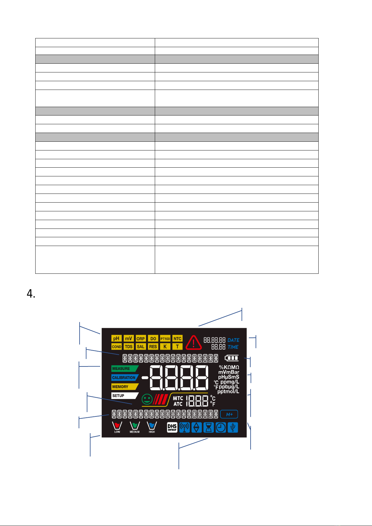
•Display .................................................................................................................................................9
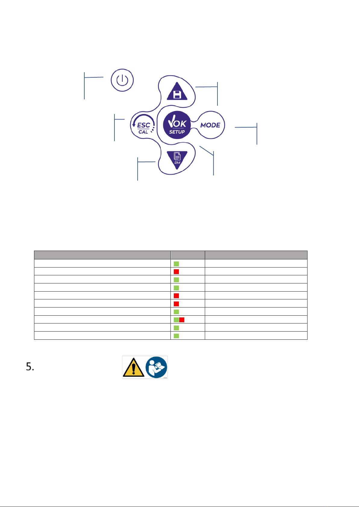
•Keyboard ...........................................................................................................................................10
•LED.....................................................................................................................................................10
Installation .............................................................................................................................................10
•Supplied components........................................................................................................................10
•Start-up..............................................................................................................................................11
•Connection of the power supply.......................................................................................................11
•Power on, date and time update, power off.....................................................................................11
•Replacement of batteries..................................................................................................................12
•Instrument transportation ................................................................................................................12
•Key functions.....................................................................................................................................12
•Inputs / Outputs connections ...........................................................................................................13
READ THE MANUAL BEFORE PROCEEDING TO CONNECT THE PROBES OR PERIPHERALS ........................13
•Symbols and icons on the display .....................................................................................................13
Operation of the device.........................................................................................................................14
Setup menu ...................................................................................................................................15
•Setup Menu Structure .....................................................................................................................16
Temperature measurement ATC – MTC ....................................................................................16
%O2 Parameter .............................................................................................................................17
•O2parameter Setup ..........................................................................................................................17
•Composition of the Setup menu for O2 Parameter...........................................................................17
•Information about LDO70 probe.......................................................................................................19

4
•Measuring principle ..........................................................................................................................19
•Probe storage ....................................................................................................................................19
•Oxygen sensor calibration ...............................................................................................................19
•Calibration in air at 100% ..................................................................................................................19
•Calibration with zero oxygen standard .............................................................................................20
•Calibration range ...............................................................................................................................21
•Errors during calibration ..................................................................................................................21
Dissolved oxygen measurement ..................................................................................................21
•Before starting...................................................................................................................................21
•Measure Mode..................................................................................................................................21
•Performing the measurement...........................................................................................................22
•Barometric pressure compensation ..................................................................................................22
Probe LDO70 maintenance ...............................................................................................................22
•Replacement of luminophore ...........................................................................................................22
Data Logger Function ........................................................................................................................23
•Setup for Data Logger parameter .....................................................................................................23
•Composition of setup menu for the Data Logger menu ...................................................................23
•Example of automatic Data Logger mode .........................................................................................24
•Example of manual Data Logger mode .............................................................................................24
•Recall Memory .................................................................................................................................25
•Clear the saved data..........................................................................................................................25
Instrument Setup menu .................................................................................................................25
•Composition of the setup menu for Setting menu ...........................................................................25
DataLink+ Software (per Windows 7/8/XP/10) .................................................................................27
•Functions ...........................................................................................................................................27
Warranty ...........................................................................................................................................28
•Warranty period and limitations .......................................................................................................28
Disposal of electrical devices ............................................................................................................28
XS Instruments
Via della Meccanica n.25
41012 Carpi (MO) ITALY
Tel.+39059.653274 Fax +39059653282
www.xsinstruments.com

5
Introduction
XS Instruments, globally recognized as a leading brand in the field of electrochemical measurements, has
developed this new line of portable instruments completely produced in Italy, finding the perfect balance
between performance, attractive design and ease of use.
The robustness and integrity of the case, the integrated brightness sensor and the practical carrying case
make this instrument ideal for measurements directly in the field.
Thanks to the triple power supply and the ability to manually change the contrast and brightness of the
display, this instrument is also suitable for use in the laboratory.
The innovative high definition colour LCD display shows all the necessary information, such as the
measurement, the temperature, the buffers used for the last calibration (also custom), the condition of
stability.
Everyone can use these tools thanks to the instructions that appear directly on the display. The calibration
is guided step by step and the instrument configuration menu is easy to consult. In addition, a LED
indicates the status of the system to the user.
Up to 2 calibration points can be carried out for the dissolved oxygen measurement with automatic
recognition of values.
It is possible to consult the calibration data anytime and the representation makes the calibration process
more efficient, through the icons of the buffers used.
Automatic or manual Data Logger function with values that can be stored in different GLP formats on the
internal memory (1000 data) or on the PC.

6
Safety information
•Definitions of warning words and symbols
This manual contains extremely important safety information, in order to avoid personal injury, damage to
the instrument, malfunctions or incorrect results due to failure to comply with them. Read entirely and
carefully this manual and be sure to familiarize with the tool before starting to work with it.
This manual must be kept near to the instrument, so that the operator can consult it easily, if necessary.
Safety provisions are indicated with warning terms or symbols.
•Reporting terms:
ATTENTION for a medium-risk hazardous situation, which could lead to serious injury or death, if
not avoided.
ATTENTION for a dangerous situation with reduced risk which can cause material damage, data loss
or minor or medium-sized accidents, if not avoided.
WARNING for important information about the product
NOTE for useful information about the product
Warning symbols:
Attention
This symbol indicates a potential risk and warns you to proceed with
caution.
Attention
The instrument must be used following the indications of the reference
manual. Read the instructions carefully.
Advice
This symbol draws attention to possible damage to the instrument or
instrumental parts.
Note
This symbol highlights further information and tips.
Attention
This symbol draws attention to a possible danger from electric current.

7
•Additional documents for safety
The following documents can provide the operator with additional information to work with the measuring
system safely:
•operating manual for electrochemical sensors;
•safety data sheets for buffer solutions and other maintenance solutions (e.g. storage);
•specific notes on product safety.
•Use according to destination
This instrument is designed exclusively for electrochemical measurements both in the laboratory and
directly in the field.
Pay attention to the technical specifications shown in the INSTRUMENT FEATURES / TECHNICAL DATA table;
any other use is to be considered unauthorized.
This instrument has been manufactured and tested in compliance with EN 61010-1 safety standards relating
to electronic instruments and has left the factory in perfect technical and safety conditions (see test report
in each package).
The regular functionality of the device and the operator safety are guaranteed only if all the normal
laboratory safety standards are respected and if all the specific safety measures described in this manual
are observed.
•Basic requirements for a safe use
The regular functionality of the device and the operator safety are guaranteed only if all the following
indications are respected:
•the instrument can be used in accordance with the specifications mentioned above only;
•use the supplied power supply only. If you need to replace the power supply, contact your local
distributor;
•the instrument must operate exclusively in the environmental conditions indicated in this manual;
no part of the instrument can be opened by the user.
Do this only if explicitly authorized by the manufacturer.
•Unauthorized use
The instrument must not run, if:
•it is visibly damaged (for example due to transportation);
•it has been stored for a long period of time in adverse conditions (exposure to direct light, heat sources
or places saturated by gas or vapours) or in environments with conditions different from those
mentioned in this manual.
•Device maintenance
If used correctly and in a suitable environment, the instrument does not require maintenance procedures.
It is recommended to occasionally clean the instrument case with a damp cloth and a mild detergent. This
operation must be performed with the instrument off.
The housing is in ABS / PC (acrylonitrile butadiene styrene / polycarbonate). This material is sensitive to
some organic solvents, for example toluene, xylene and methyl ethyl ketone (MEK).

8
If liquids get into the housing, they could damage the instrument.
Do not open the instrument housing: it does not contain parts that can be maintained, repaired or replaced
by the user. In case of problems with the instrument, contact your local distributor.
It is recommended to use original spare parts only. Contact your local distributor for information. The use
of non-original spare parts can lead to malfunction or permanent damage to the instrument. Moreover, the
use of spare parts not guaranteed by the supplier can be dangerous for the user himself.
For the maintenance of the electrochemical sensors, refer to the documentation present in their packaging
or contact the supplier.
•Responsibility of the owner of the instrument
The person who owns and uses the tool or authorizes its use by other people is the owner of the tool and
is responsible for the safety of all users of the tool and third parties.
The owner of the instrument must inform users of the use of the same safely in their workplace and on the
management of potential risks, also providing the required protective devices.
When using chemicals or solvents, follow the manufacturer's safety data sheets.
Instrumental features
•Parameters
OXY 70 Vio: % O2, mg/l, mbar, Temp
•Datasheet
OXY 70 Vio (optical sensor)
Dissolved O2
Measuring range
0,00…19,99 mg/l / 20,0…50,0 mg/l - ppm
Resolution
0,1 / 0,01
Accuracy
± 0,2 up to 10 mg/l-ppm
± 0,3 from 10 to 20 mg/l-ppm
± 5% in the range from 20 to 50 mg/l-ppm
Dissolved O2 saturation measuring range
0,0…199,9 % / 200…400%
Resolution
0,1 / 1%
Accuracy
± 10%
Oxygen calibration points
1 or 2 automatic
Calibration points indication
Yes
Calibration report
Si
Barometric pressure measuring range
0…1100 mbar
Resolution
1 mbar

9
Accuracy
± 0,5%
Automatic temperature compensation ATC
Yes
Temperature
Measuring range
-10,0…110,0 °C
Resolution
± 0,1°C
Accuracy
± 0,5°C
Temperature compensation ATC and
MTC
Yes, automatic only
Salinity
Measuring range
0…50 ppt
Salinity compensation
Si, manuale
System
GLP with calibration Timer
Yes
Internal memory
1000 Data
Display
High definition colour LCD
Brightness and contrast management
Manual and automatic with integrated sensor
IP protection
IP 57
Power supply
AA 1,5 V – 3 batteries / 5 V power supply with USB cable
Sound level during standard operation
< 80 dB
Environmental operating conditions
0 … +60 °C
Maximum permissible humidity
< 95 % non-condensing
Maximum altitude of use
2000 m
System dimensions
185 x 85 x 45 mm
System weight
400 g
Reference regulations
EMC 2014/30/UE
RoHS 2011/65/EU
EN 61326-1
EN 61010-1
Instrument description
•Display
Measurement
parameter
Indication of
instrumental
mode
Representation of
buffers used for
calibration
Error symbol
Actual value / Measure unit
Temperature and type of
compensation
ATC - automatic NTC 30KΩ
MTC - manual
Information icons
on connectivity and Data
Logger
Progressive number of data saved in
Data Logger mode
Stability
indicator
Text string
Date and time
Battery charge level
Text string

10
•Keyboard
•LED
All the instruments are equipped with a two-colour LED (red and green) which provides the user with
important information on the status of the system:
Funzione
LED
Descrizione
Power on
Fixed
Power off
Fixed
Standby
Flashing every 20 s
Stable measure
Flashing every 3 s
Errors during calibration
Flashing every 1 s
Errors during measurement
Flashing every 3 s
Time of saving the data
On / Off in rapid succession
Recall Memory mode
Alternate green and red, pause 5 s
Selection confirmation
Switched on for 1 s
Timed screens
Fixed
Installation
•Supplied components
The instrument is always supplied inside the specific carrying case with these accessories:
batteries, adaptor 5V with USB cable, standard 0 oxygen, paper tissues, screwdriver, beacker, multilingual
user manual and test report.
Contact your local distributor to be updated on the correct composition of the sales kit and spare parts.
Down directional key to scroll through
the menus and parameters and to
manage the recall of data
MODE key to scroll through the
various measurement parameters
Enter / Menu key to confirm the chosen values
and enter the setup from the measure mode
On-Off button to
switch the device on
and off
Meas / Cal key to return to measure
mode and to start calibration
Up directional key for scrolling
through menus and parameters
and managing data saving

11
•Start-up
•The device leaves the factory ready to be used by the user.
•Batteries are included.
•Connection of the power supply
•in addition to batteries, the instrument can be powered through electricity grid;
•check that the electrical standards of the line on which the instrumentation is to be installed
comply with the voltage and operating frequency of the instrument;
•use the original power supply only;
•connect the power supply to the USB cable and the other end of the cable (Micro USB) to the
Micro USB port located on the front of the instrument;
•Connect the power supply to an electric socket easy to reach.
The electricity supply can be originated from the power grid and from the USB port of a PC too.
If the instrument is powered by PC, the icon indicating the battery status disappears from the display .
Opening the DataLink+ software, on the display it is shown this icon .
•Power on, date and time update, power off
Turn on the system by pressing the button . The display initially activates all segments and then
appears:
•model and firmware of the instrument;
•settings relating to the most important parameters and possible information about the DHS sensor;
On first use, and after each battery replacement, the instrument during the start-up phase will request the
updating of the date and time.
•Using the directional keys, update the year and confirm with the key . Carry out the same
operation with the month and day, and subsequently with hours and minutes.
•The instrument will enter measure mode in the last parameter used.
To switch off the instrument, press the key in measure mode.
ATTENTION
Danger of death or serious injury from electric shock.
Contact with live components can lead to injury or death.
•Use the adapter supplied only.
•Do not put the power supply in contact with liquids nor in a condensing environment. Avoid
thermal shock.
•All electrical cables and connections must be kept away from moisture or liquids.
•Check that the cables and plugs are not damaged, otherwise replace them.
•During use, do not cover the power supply and/or do not place it inside containers.

12
•Replacement of batteries
The instrument works with 3 AA 1.5V batteries.
To proceed with the replacement:
1. Turn off the device.
2. Turn the instrument over with the display facing down and place it on a stable surface.
It is advisable to put a cloth to avoid any scratching on display.
3. Using the screwdriver supplied, completely unscrew the screw close to the battery symbol.
4. Remove the battery stopper cap with the help of the lanyard.
5. Remove the 3 exhausted batteries (one in the left compartment and two in the right compartment)
and insert the new ones. Pay attention to the correct polarity. Follow the diagram above the battery
symbol in the rear compartment of the instrument.
6. Reinsert the battery holder and tighten the screw.
•Instrument transportation
The instrument is always supplied with the appropriate carrying case. Use the original case only, to transport
the instrument. If you need to buy it again, contact your local distributor.
The interior of the case is shaped to be able to house the instrument and the sensors still connected.
•Key functions
Button
Pression
Function
Short
Press to turn the device on or off.
Short
In measure mode, press to scroll through the different parameters:
•OXY 70 Vio: % O2mg/l mbar
Short
•In calibration mode, press to return to measure mode.
•In measure mode, press to start the calibration.
Short
In measure mode, press to enter the setup.
In the setup menus, press to select the desired program and / or value.
During calibration, press to confirm the value.
Short
In the setup and subset menus press to scroll
In the setup submenus, press to change the value
In memory recall mode, press to scroll through the saved values.
In MTC and customer calibration mode, press to change the value.
: In measure mode, press to save the data (manual Data Logger) or start
and end the recording (Automatic Data Logger).
: In measure mode, press to recall the saved data.

13
Long-press
(3s)
In measure mode, keep one of the two keys pressed to change the temperature
in MTC mode (manual compensation, without probe). When the value starts to
flash, the user can change the temperature value by entering the correct one and
confirming with .
IMPORTANT:
•When the Sleep mode is active (by default after two minutes of inactivity of the instrument) press
any key to reactivate the brightness of the display.
•Only at this point do the keys regain their function.
•Inputs / Outputs connections
Use original accessories guaranteed by the manufacturer only.
If necessary, contact your local distributor.
OXY 70 Vio top panel
READ THE MANUAL BEFORE PROCEEDING TO CONNECT THE PROBES OR PERIPHERALS
•Symbols and icons on the display
Symbol
Description
Symbol
Description
M+
Number of data stored in Data Logger
mode on instrumental memory
Error in measurement or calibration
Instrument connected to the DataLink+
software
FIXED: Automatic Data Logger set
INTERMITTENT:
Automatic Data
Logger in operation
6 pin connector for optical
sensor
Micro USB port for
connection to PC and
power supply

14
FIXED: Calibration deadline set for that
parameter
INTERMITTENT: Calibration deadline
active for that parameter
Press the directional keys to change
the parameter or value on the
display
Measurement stability indicator
Battery charge indication
The bars scroll if the measurement is
not stable
Operation of the device
•After the switching on, the instrument enters measure mode in the last screen before turning off.
•To scroll through the different parameter screens, press the key .
Sequence of parameters in measure mode:
OXY 70 Vio
% O2
mg/l
mbar
Note: Pressing the button after the last parameter, the instrument automatically restarts from the
first one.
In the measurement screen for %O2and mg/l, press the key to start the calibration of the active
parameter (next paragraphs).
On the left side of the display, through a string of different colours, it is always indicated how the
instrument is located.
Note: in order to confirm to the user the switching from one mode to another, the string flashes.

15
String
Meaning
The instrument is in measure mode.
The instrument is in calibration (automatic or manual in relation to
the user's choice).
The user is in the setup mode.
The configuration menus can concern the characteristics of the
parameters or the general setting of the instrument.
The instrument is in the Recall Memory mode.
The data stored are being displayed by running the manual or
automatic Data Logger.
Setup menu
•In measure mode, press the key to enter SETUP mode, select the parameter to edit by using the
directional keys and confirming with .
OXY 70 Vio
DO SETTINGS
LOG SETTINGS
SETTINGS
•Within the selected menu, move between the different programs using the directional buttons and
press the button to access the submenu you want to edit.
•Using the keys and choose the desired option or change the numerical value and confirm
with .
•The value or parameter that is being edited is recognizable as it flashes on the display.
•The icon indicates that the value or parameter to choose is editable using the directional keys.

16
•Press the key to return to the previous menu.
•Setup Menu Structure
P5.0
DO SETTINGS
P5.1
Cal 0
P5.2
Salt Compensation
P5.6
Cal Data
P5.7
Set Due Cal
P5.8
Reset Settings
P5.9
Temp Cal
P8.0
LOG SETTINGS
P8.1
Data Logger Type
P8.2
Clear Data
P9.0
SETTINGS
P9.1
Temperature U.M.
P9.2
Time and data Set
P9.3
Backlight mode
P9.4
Brightness
P9.5
Sleep Mode
P9.8
Reset Settings
P9.9
Auto Power-Off
Temperature measurement ATC – MTC
•ATC: The direct measurement of the sample temperature for all parameters is carried out through the
NTC 30KΩprobe, integrated into the sensor.
•MTC: If no temperature probe is connected, the value must be changed manually: keep pressed
or until the value starts to flash; then adjust it by continuing to use the directional keys; press
to confirm.
Note: with the optical sensor supplied together with the instrument, the manual temperature
compensation (MTC) IS NOT TO BE PERFORMED.

17
%O
2
Parameter
Connect the optical sensor to the 6-pole multipin connector.
It is not necessary connect an external temperature probe, because it is already integrated.
Connettere il sensore ottico al connettore di tipo Multipin 6 poli.
Once switched on, the device does not require any polarization time. There, it is ready for use (calibration
and/or measurement).
•O2parameter Setup
•In measure mode press to access the SETUP menu.
•Press the button to access the DO SETTINGS P5.0 menu.
Move with the keys and to select the program to access.
The table below shows the setup menu structure for the O2parameter, and for each program the options
that the user can choose and the default value:
•Composition of the Setup menu for O2 Parameter
Program
Description
Options
Factory Default Settings
P5.1
CAL 0
-
-
P5.2
SALT COMPENSATION
0.0 – 50.0
0.0
P5.6
CALIBRATION DATA
-
-
P5.7
SET DUE CAL
NO – HOURS - DAYS
NO
P5.8
RESET SETTINGS
YES – NO
NO
P5.9
TEMPERATURE CAL
YES – NO
-
P5.1 Cal 0 (Calibration with Standard Zero 02)
•Access this setup menu to select the calibration with Standard (supplied together with the device in the
carrying case) Zero Oxygen (next paragraphs “Calibration”).
•Once confirmed the operation, in measure mode on the lower left in the display, the beaker
indicates the point % 02= 0 on which the calibration was performed.
•P5.2 Salt Compensation (manual)
•
•The salinity of the sample to be measured influences the partial pressure of the dissolved oxygen.
For a correct measurement, it is necessary to set the salinity value of the sample. If oxygen
measurements are carried out on salt or sea water samples, it is important to modify the
measurement by setting the indicative salinity value of the sample.
•The default value is 0 ppt, access the parameter SALT COMPENSATION P5.2 of the setup menu to
change it and select the desired value between 0.0 … 50ppt.
•The average salinity of the sea water is 35ppt.
P5.6 Calibration data O2

18
Access this menu to get information on the last performed calibration. The following screens will
automatically scroll on the display:
•First screen: Beakers indicating the points (0% - 100% O2) on which the calibration was performed.
•Second screen: OFFSET value of the sensor expressed in %.
•Third screen: EFFICIENCY of the sensor, expressed in Slope %.
•Fourth screen: Value of COMPENSATION of Salinity, expressed in ppt.
•Fifth screen: Value of BAROMETRIC PRESSURE, expressed in mbar, at which the calibration was
performed.
•Sixth screen: TEMPERATURE at which the calibration was performed.
•Note: The instrument accepts calibrations with Oxygen sensors with Slope % between 80 – 120%.
•Outside this range of acceptability, the instrument does not allow to end the calibration and displays
the error message SLOPE OUT OF RANGE
P5.7 DO Calibration deadline (Set Due Cal)
Access this menu to set a calibration deadline; this option is very important in GLP protocols.
•By default, no calibration deadline is set. Use the directional keys to select HOURS or DAYS and access
with button . Use the directional keys to change the number that appears in the center of the
display, entering the hours or days that must elapse between two settings, and confirm with .
•If a calibration deadline is set, the icon is present on the display in measure mode.
•When the calibration deadline is activated, the instrument prevents further measurements.
The error icon and the icon representing the calibration deadline flash on the display.
The string “MAKE A NEW CAL” invites the user to perform a new calibration of the pH sensor to be
able to work again.
Press the key to start the calibration.
P5.8 Reset of the DO parameter (Reset Settings)
If the instrument does not work properly or incorrect calibrations have been carried out, confirm YES with
button , in order to take all the parameters of the DO menu back to the default settings.
IMPORTANT: The factory reset of the parameters DOES NOT erase the stored data.
P5.9 Temperature calibration
All the instruments of this series are pre-calibrated for a correct temperature reading. However, if there is a
difference between the measured and the real temperature (usually due to a probe malfunction), it is
possible to perform an offset adjustment of + 5°C.
After the connection of the temperature probe, use the keys and to correct the temperature
offset value and confirm with .

19
•Information about LDO70 probe
The LDO70 probe uses a luminescence optical technology for dissolved oxygen measurements in water.
This type of probe has many advantages compared to classical polarographic type sensor, some of these
are:
•Zero polarization time, the instrument is always ready
•No shaking of the sample because there is no oxygen consumption
•No electrolyte in the membrane
•No interferences with other gases (e.g. CO2)
•Reduced maintenance time
•Very fast response time
•Accurate even with small sample volumes
•Stable and accurate measurements even at low dissolved oxygen value.
•Measuring principle
On a permeable membrane to oxygen has been fixed a chemical substance called luminophore. Inside the
sensor, a light source pulses a light of blue colour that is reflected from the luminophore on an inner
photocell. When the oxygen, permeating through the membrane, comes in contact to the luminophore, it
modifies the blue light in proportion to the partial pressure of the oxygen. This variation is read by the
photocell which generates a proportional electrical signal.
•Probe storage
When the probe is not in use, store it in the storage cap containing distilled water. In this way, the
membrane is protected and hydrated, ready for use.
•Oxygen sensor calibration
The luminophore of the optical sensor is subject to aging and wear, therefore, you need to calibrate it
regularly in the air.
•Calibration in air at 100%
The ordinary calibration is performed at 100% in air.
Turn the instrument on, dip the probe in water and wait for the polarization time of 10 minutes.
Later, dry the probe thoroughly with paper towel and proceed as follows:
Membrane on which is fixed
the luminophore
O-ring

20
•Place the probe in air with the membrane facing downwards and wait for 2 minutes. Then, connect the
sensor to the device.
•In measure mode, press the key to enter in calibration mode.
On the display, it appears the string “POINT oxy 100.0”; the device will look for the value %O2= 100 %.
Keep the sensor in air in a vertical position with the membrane facing downwards.
•When the signal is stable, the red bands will be replaced by the stability icon .
Press the button , as indicated by the string “PRESS OK”.
On the display, the measured value flashes, then the sensor and finally the beacker appears
below on the left and indicates that the instrument is calibrated on value 100%O2.
•After the calibration, the instrument enters in measure mode automatically.
•Calibration with zero oxygen standard
Normally, it is enough to calibrate the instrument in the air at 100% as explained previously. However,
sometimes it is also necessary to calibrate at 0%, for example when:
•A probe or luminophore is replaced by a new one
•The probe is not used for a long period of time (3-6 months)
•The instrument does not calibrate at 100%, in this case calibrate it before at 0%.
•The instrument does not measure correctly
For calibration at 0%, proceed as follows:
Turn the instrument on, rinse the probe in distilled water; dry the probe thoroughly with paper towel and
proceed as follows:
•Put the probe in the Zero Standard Oxygen and wait for 5 minutes.
•In measure mode, press the button , remain in Menu DO SETTINGS P5.0 and confirm pressing
the button again.
•Press the button again, confirm the entry into submenu CAL 0 P5.1.
•On the display, the string “POINT oxy 0.0” appears; the device will search for the value %O2= 0%.
•Gently stir the probe in the Standard and eliminate any air bubbles under the membrane, moving
the sensor.
•The scrolling on the display of four red bands means that the measurement is not stable yet.
•Consider the measurement truthful only when the stability icon appears .
•Confirm the value by pressing the button .
•The instrument automatically returns to measure mode.
•The beaker icon appears at the bottom left, indicating that the instrument is calibrated on value
0% O2.
Table of contents
Other XS Analytical Instrument manuals