XTM Racing X-Terminator 2e User manual

Page 1
Kit Product # 145626 (U.S.) / C-XTM-XT2E (Europe)

Page 2
TABLE OF CONTENTS
Before operating your new X-Terminator 2e, please read and understand the warnings listed on the next page. Failure to do
so could lead to injury and/or property damage. The X-Terminator 2e is not intended for persons under 14 years of age, unless
closely supervised by an adult.
l Heavy-Duty Aluminium Front and Rear Chassis Bracing
l Balanced Weight Distribution for Stable Handling
l Adjustable Toe-in, Front and Rear
l Adjustable Camber, Front and Rear
l 4mm Aluminium Shock Towers
l Heavy-Duty Drive-Line with Chrome-Plated Front CVDs
l Complete Hex Head Steel/Alloy Screw Set
l Gearboxes Allow Easy Differential Removal
l Adjustable Differentials with the Use of After-Market Silicone Oils
l High-Grip, All-Terrain Tyres Mounted on Satin Chrome Wheels
l Optional Parts Available for Increased Performance and Handling
l Weight (Without Batteries) .............................................................................................................................................. 3.63kg (8.0lbs)
l Length ............................................................................................................................................................................. 483mm (19.0")
l Width ............................................................................................................................................................................... 305mm (12.0")
l Height (Measured to the Top of the Body Shell with Settled Suspension) ........................................................................ 154mm (6.1")
l Wheelbase (Adjustable) ....................................................................................................................324mm ~ 330mm (12.75" ~ 13.0")
l Factory-Assembled with Factory-Printed Body Shell
l Uses 6 ~ 12 Cell Ni-MH Batteries or 2 ~ 4 Cell Li-Po Batteries
l High-Current Sensored/Sensorless Electronic Speed Controller
l High-Powered 1/8th Scale Brushless Motor
l Program Card for Customised Electronic Speed Controller Settings
l Electronic Speed Controller Cooling Fan and Motor Heat-Sink
l Full Set of Sealed Ball Bearings for Drive-Line
l High-Torque Metal-Geared Steering Servo
l Lay-Down Steering Servo for Lower Centre of Gravity
l Fully-Threaded Aluminium Shocks with 3.5mm Shock Shafts
l Bevel Differentials - Front, Rear and Centre
INTRODUCTION
Thank you for your purchase of the XTM Racing X-Terminator 2e Brushless 4WD Buggy. The X-Terminator 2e is a high-quality, powerful,
1/8th scale brushless-powered buggy that offers both the casual user and the racer tremendous value. Whether it's racing on the track
or just bashing in a eld, the X-Terminator 2e is ready to tear up the terrain and carve through the curves with ease.
This Operating Manual is designed to help you get your X-Terminator 2e up and running as quickly as possible. In addition to basic
information about your new model, this Operating Manual includes pro tips, a chassis tuning guide, detailed exploded view assembly
drawings and a complete replacement parts list with option parts. Be sure to keep this Operating Manual handy for future reference!
n
X-Terminator 2e Features
n
X-Terminator 2e Specications
Introduction ...................................................................................... Page 2
X-Terminator 2e Features ............................................................ Page 2
X-Terminator 2e Specications .................................................... Page 2
Customer Service Information ......................................................... Page 3
Safety Warnings and Important Information .................................... Page 3
General Warnings ........................................................................ Page 3
Brushless Power System Warnings and Information .................. Page 3
Lithium Polymer (Li-Po) Battery General Warnings ..................... Page 4
Battery Instructions for Disposal .................................................. Page 4
Kit Contents ..................................................................................... Page 4
Items Required to Operate and Maintain......................................... Page 5
Battery Requirements .................................................................. Page 5
Miscellaneous Requirements ...................................................... Page 5
ESC Programming Card Requirements ...................................... Page 5
Becoming Familiar with Your X-Terminator 2e ................................ Page 6
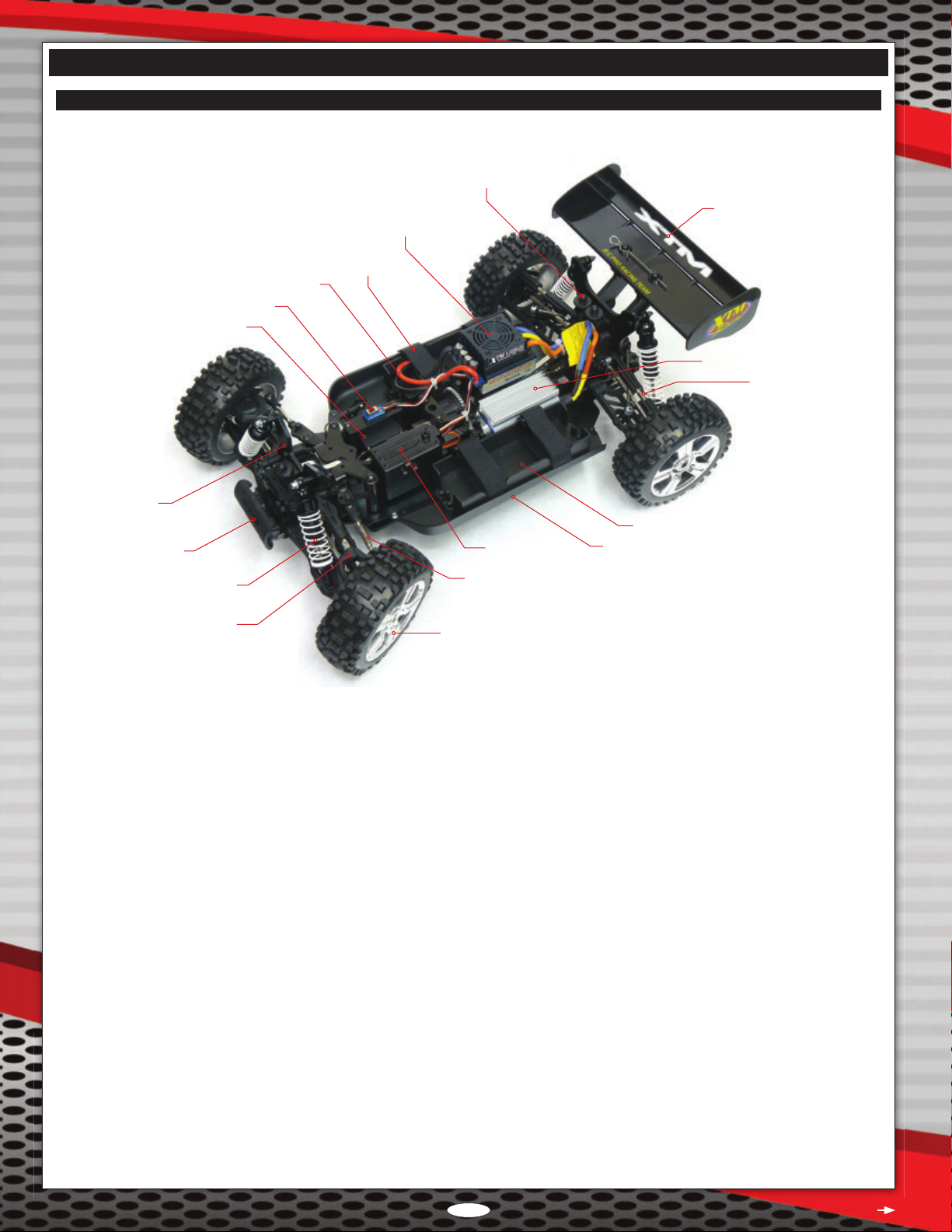
Chassis Component Overview .................................................... Page 6
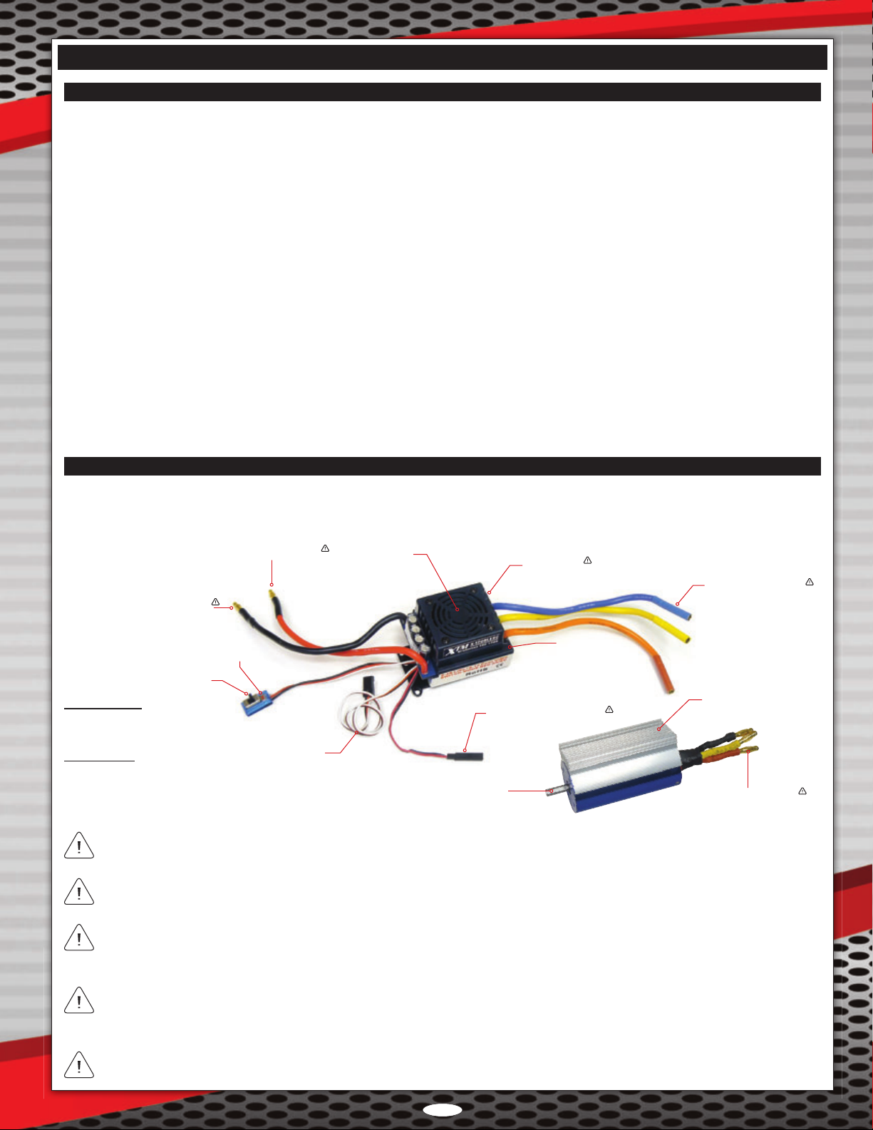
Brushless Power System Overview ............................................ Page 7
Tips From the Pros .......................................................................... Page 8
Preparing to Run Your X-Terminator 2e .......................................... Page 8
Transmitter and Receiver ............................................................ Page 8
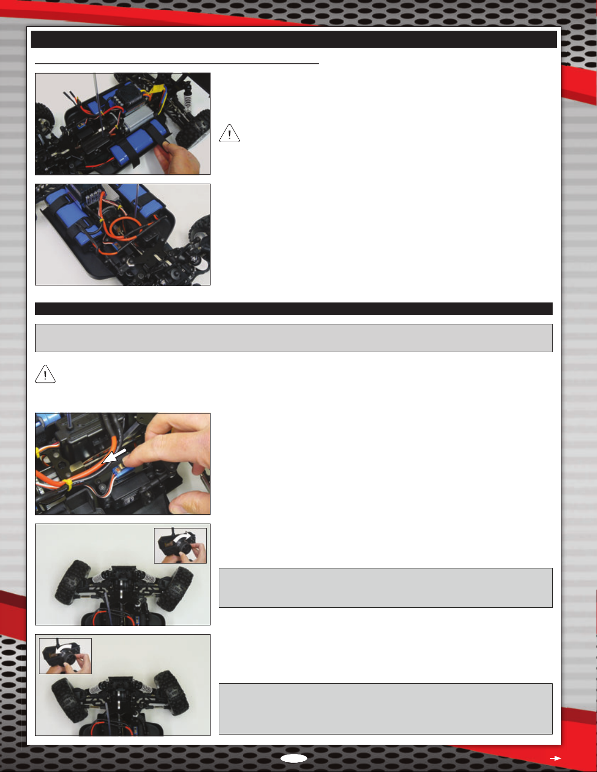
Battery Pack Installation and Power Connections ....................... Page 9
Checking the Steering and Throttle Controls............................. Page 10
Throttle Control Range Calibration ............................................ Page 11
Using the ESC Programming Card ........................................... Page 11
Installing the Body ..................................................................... Page 13
Chassis Tuning Guide ................................................................... Page 14
Adjusting Toe Angle - Front and Rear........................................ Page 14
Adjusting Gearing ...................................................................... Page 14
Adjusting Camber Angle - Front and Rear ................................ Page 15
Adjusting Shock Spring Tension - Front and Rear..................... Page 15
Changing Shock Springs - Front and Rear ............................... Page 16
Adjusting Shock Damping - Front and Rear .............................. Page 16
Adjusting Shock Mounting Positions - Front and Rear .............. Page 16
Adjusting Bump Steer - Front .................................................... Page 17
Adjusting Droop - Front and Rear ............................................. Page 17
Adjusting Steering Sensitivity - Front ........................................ Page 17
Adjusting the Differentials - Front, Centre, and Rear................. Page 18
Maintenance Guide ....................................................................... Page 19
Adjusting Gear Mesh ................................................................. Page 19
Troubleshooting Guide .................................................................. Page 20
Exploded View Assembly Drawings .............................................. Page 21
Replacement Parts List ................................................................. Page 49
Option Parts List ............................................................................ Page 54
Returning Your Product for Warranty Repair ................................. Page 59
Warranty Information ..................................................................... Page 59

Page 3
If you should have trouble with any of the steps listed in this Operating Manual, or if you nd a missing or a damaged part
in your kit or require additional information, please contact your regional distributor at the address below:
Global Services
18480 Bandilier Circle
Fountain Valley, CA 92708
Phone: (714) 963-0329
Fax: (714) 964-6236
Email: service@globalhobby.net
Ripmax Ltd.
241 Green Street
Eneld, EN3 7SJ, U.K.
Phone: (0) 20 8282 7500
Fax: (0) 20 8282 7501
Email: [email protected]
CUSTOmER SERvICE INFORmATION
SAFETY WARNINGS AND ImpORTANT INFORmATION
l Under no circumstances should you operate your model in crowds of people. Serious injury could result.
l Never operate your model on busy streets or if there are cars around.
l Do not use your model to chase pets or other animals.
l The electronics in your model are not waterproof. Therefore, do not drive through water, wet grass, mud or snow.
l Because your model is operated by radio control, it is important to make sure you always use fresh and/or fully charged batteries (if
using Ni-Cds or Ni-MHs). Never allow the batteries to run low or you could lose control of the model.
l If your model becomes stuck, do not continue to apply power or damage can occur. Release the throttle and retrieve your model by hand.
l To prevent excessive r.p.m.s from damaging your motor and/or drivetrain components, we suggest reducing power while in the air
during jumps.
n
General Warnings
l Your X-Terminator 2e is tted with an extremely powerful brushless power system. For your safety, please use caution at all times to
keep your hands, loose clothing, etc., away from any moving parts.
l For your safety and the safety of others, prior to making any programming changes to the electronic speed controller using the included
ESC programming card, we strongly suggest removing the pinion gear from the motor. This will prevent any chance of a runaway model.
l The tyres on your model will 'balloon' to a larger diameter when mounted on a high-speed model, such as the X-Terminator 2e. DO
NOT hold the model in the air and run it up to full throttle or tyre failure could occur. Check the tyres often to ensure that they're
securely glued onto the wheels.
l After soldering connectors onto your batteries, and when plugging your batteries into the ESC, make sure to observe correct polarity.
This will ensure that when you plug the batteries into the ESC that you do not plug them in with reverse polarity. Plugging the batteries
in with reverse polarity will damage the ESC and possibly damage your batteries.
l The power output of the brushless power system is dependent on the type and quality of the batteries and battery connectors that
you use. While the power system will provide good power using lower-quality batteries, to take full advantage of the power
available, we recommend the use of high-quality batteries and connectors. We provide high-quality gold-plated Bullet connectors on
your model. We recommend keeping these connectors and using the equivalent on your batteries.
n
Brushless Power System Warnings and Information
XTM Racing guarantees this kit to be free from defects in both material and workmanship, at the date of purchase. This does
not cover any component parts damaged by use, misuse or modication. In no case shall XTM Racing's liability exceed the
original cost of the purchased kit.
Continued On Next Page
In that XTM Racing has no control over the nal assembly or material used for nal assembly, no liability shall be assumed for any
damage resulting from the use by the user of the nal user-assembled product. By the act of using the nal user-assembled product,
the user accepts all resulting liability. For detailed warranty information, refer to page 59.

Page 4
These products must not be disposed of with other household waste. Instead, it is the user's responsibility to dispose of these
products by handing them over to a designated collection point for the recycling of waste electrical and electronic equipment. The
separate collection and recycling of these products at the time of disposal will help to conserve natural resources and ensure that
they are recycled in a manner that protects human health and the environment.
For more information about where you can take these products for recycling, please contact your local city or municipal ofce,
your household waste disposal service, or where you purchased the product.
Lithium Polymer (Li-Po) batteries are signicantly more volatile than Alkaline or Ni-Cd/Ni-MH batteries used in R/C applications.
When using Li-Po batteries to power your model, all instructions and warnings must be followed closely. Mishandling of Li-Po batteries
can result in re. In addition to the general Li-Po battery warnings below, be sure to understand and follow the warnings included with
the particular Li-Po batteries you use.
l ALWAYS follow the instructions included with your Li-Po batteries and/or Li-Po charger to charge Li-Po batteries.
l DO NOT attempt to charge Li-Po batteries with any charger other than a charger designed to charge Li-Po batteries. The Li-Po battery
charger you use should include a balancing feature.
l DO NOT leave Li-Po batteries unattended during the charging process.
l ALWAYS charge Li-Po batteries on a re-resistant surface and never charge Li-Po batteries near any ammable material.
l DO NOT use or charge Li-Po batteries if they are hot to the touch.
l DO NOT leave Li-Po batteries in direct sunlight or in a hot car or storage area, or allow Li-Po batteries to be exposed to moisture.
l DO NOT short-circuit Li-Po batteries.
l DO NOT leave Li-Po batteries plugged into your model when not in use. Li-Po batteries should be stored in a re-proof container.
l ALWAYS let Li-Po batteries cool between uses and charging.
l INSPECT Li-Po batteries before each use for swelling or other malformation. If damaged, they should not be used.
l DO NOT poke, bend or otherwise damage Li-Po batteries. DO NOT short-circuit.
l DO NOT allow Li-Po batteries to ever exceed 71ºC (160ºF) for any reason.
SAFETY WARNINGS AND ImpORTANT INFORmATION
n
Alkaline, Ni-Cd, Ni-MH, and Li-Po Battery Instructions for Disposal
n
Lithium Polymer (Li-Po) Battery General Warnings
kIT CONTENTS
After opening your X-Terminator 2e, remove all of the parts from the box and double-check that you have all of the items listed below.
If you nd a part is missing or damaged, please contact your regional distributor, using the Customer Service Information on page 3.
l Tyres and Wheels (Glued)*
l Body Clips*
l Decal Set
l Receiver Antenna Support Tube
l Suspension Plate Holders
l Allen Keys and Wrenches
l Instructions for Radio Control System
l Instructions for ESC/ESC Programming Card
l X-Terminator 2e Chassis with Electronics
l Transmitter
l ESC Programming Card
l Lexan Body Shell (Printed)*
l Nylon Wing*
*May come installed on chassis and not loose in the box.
The brand and type of radio control system (transmitter, receiver, and steering servo) included with your X-Terminator 2e varies
by region. Please make sure to read through the separate radio control system Operating Manual included to learn about your
radio control system's features and proper use.
Kit contents are subject to change at any time without notice.

Page 5
ITEmS REqUIRED TO OpERATE AND mAINTAIN
The products listed below must be purchased separately and are required to run your X-Terminator 2e. We've also listed the items we
recommend you have on-hand to perform basic maintenance and for using the included ESC programming card.
n
Battery Requirements
The X-Terminator 2e can be powered using either one battery pack or two battery packs wired in series. You can use either Ni-Cd,
Ni-MH, or Li-Po battery packs.
n
ESC Programming Card Requirements
The ESC programming card can be powered by your motor batteries, or by a separate battery. If you decide to power the ESC
programming card with a separate battery, you will need the type of battery listed below. For more information, see pages 12 and 13.
l One 4 ~ 5 Cell Ni-Cd or Ni-MH Receiver Battery Pack or One 4 Cell Battery Holder with 4 'AA' Alkaline Batteries
Recommended Single Battery Pack Setup
l One 6C Ni-MH Battery Pack (4200mAh or greater) or One 2 ~ 4S (35C) Li-Po Battery Pack of desired capacity
l Two 4mm Gold-Plated FEMALE Bullet Connectors with Heat-Shrink Tubing (If not included with battery)
Recommended Two Battery Pack Setup
l Two 6C Ni-MH Battery Packs (4200mAh or greater) or Two 2S (35C) Li-Po Battery Packs of desired capacity
l Four 4mm Gold-Plated FEMALE Bullet Connectors with Heat-Shrink Tubing (If not included with batteries)
l Two 4mm Gold-Plated MALE Bullet Connectors with Heat-Shrink Tubing
l 12 AWG Silicone Wire
The ESC can handle 6 ~ 12 Ni-Cd or Ni-MH cells or 2 ~ 4 Li-Po cells in either a one pack or a two pack conguration. Do not
exceed the maximum combined cell count or the ESC will be damaged! In addition, NEVER mix Ni-Cd, Ni-MH, or Li-Po cells!
Regardless of the type of battery pack(s) you choose, the following pertains: the more cells you use, the more power the battery
pack will provide, but the heavier the battery pack will be. The higher the capacity of the battery pack (e.g., mAh), the longer the
run-time you will experience, but the heavier the battery pack will be. Whilst the capacity of the battery pack you choose can be
as high as desired (while still allowing the battery pack to t in the battery holder), the total combined cell count should never exceed
the maximum for the ESC.
In addition to the battery requirements listed above, the following items are recommended to run and maintain your X-Terminator 2e.
l 'AA' Alkaline Batteries for Transmitter (Quantity will vary depending on set included)
l AC or AC/DC Charger for Ni-Cd/Ni-MH and/or Li-Po Batteries
l Solder (for Electronics) and Soldering Iron
l Heat Gun or Lighter (for Heat-Shrink Tubing)
l Metric Ruler
l # 1 Phillips Head Screwdriver
l 1.5mm, 2mm, 2.5mm, and 3mm Hex Wrenches
l 5.5mm and 7mm Nut Drivers
l 17mm Wrench or Socket (for Wheel Nuts)
l Adjustable Wrench and Needle Nose Pliers
l Scissors or Modeling Knife
l Motor Spray and Ball Bearing Oil
l Assorted Weights of Silicone Oil to Tune Shocks and Differentials (Optional)
n
Miscellaneous Requirements
The charger you use should be compatible with the type of batteries you're using. For example, if you're using Li-Po batteries,
your charger must be able to charge Li-Po batteries.

Page 6
BECOmING FAmILIAR WITh YOUR x-TERmINATOR 2e
Use the photo and descriptions below to familiarise yourself with the X-Terminator 2e main chassis components.
Receiver Box
with Antenna Mount
Battery Holder
Wing
ESC On/Off Switch
Bumper
Battery Retaining Strap
Shock Tower
Brushless ESC
with Cooling Fan
Brushless Motor with Heat-Sink
Wheel/Tyre Assembly
Shock Absorber
Body Mount
Side Guard
Steering Servo
Steering Tie-Rod
Suspension Arm
Turnbuckle
ESC Battery Leads
n
Chassis Component Overview
Battery Holder: Moulded out of impact-resistant nylon plastic, the battery holder firmly holds the battery pack that powers the
X-Terminator 2e. The battery holder is sized to t most 6 cell Ni-Cd or Ni-MH battery packs and 2 ~ 4S Li-Po battery packs.
Battery Retaining Strap: The battery retaining strap holds the Ni-MH or Li-Po battery pack that powers the X-Terminator 2e securely in
the battery holder. The battery retaining strap makes it easy to remove the battery pack and is adjustable to t different size battery packs.
Body Mount: Moulded out of high-impact nylon plastic for strength, the body mount supports the body. There is a dual-mount body
mount at the rear of the chassis and a single-mount body mount at the front of the chassis.
Brushless ESC with Cooling Fan: The ESC is a solid-state device that takes power from the battery pack and the throttle signal from
the receiver and converts them into proportional power for the motor. The X-Terminator 2e features a high-quality 120 Amp brushless,
sensored/sensorless ESC that can handle 6 ~ 12 cell Ni-Cds or Ni-MHs, or 2 ~ 4S Li-Pos. In addition, the ESC features a 3 Amp/6 Volt
Battery Eliminator Circuit (BEC), forward and reverse control, and a cooling fan that helps keep the ESC from getting too hot. The ESC
can also be programmed using the included ESC programming card.
Brushless Motor with Heat-Sink: The brushless motor provides the power to the drivetrain. Brushless motors are more efcient and
produce more power than brushed motors. The X-Terminator 2e features a powerful 2370kV brushless motor that includes a heat-sink
to help keep motor temperatures under control.
Bumper: Moulded out of impact-resistant nylon plastic, the bumper protects the chassis from most head-on impacts.
ESC Battery Leads: The ESC battery leads are where you plug your battery pack in to power your X-Terminator 2e. The ESC battery
leads feature high-quality 12 AWG silicone wire and gold-plated 4mm male Bullet connectors.
ESC On/Off Switch: Turns the ESC 'ON' and 'OFF'. The ESC On/Off switch features a Set button, which is used in the throttle control
range calibration feature. For more information, see page 11.
Receiver Box with Antenna Mount: This is where the receiver is mounted. The receiver box protects the receiver from dust, dirt and debris.
The top of the receiver box features a moulded antenna mount that the plastic antenna tube ts into. The receiver box is not waterproof.
Continued On Next Page

Page 7
Please make sure to read through the separate Brushless Speed Controller User Manual included to learn more about the ESC's
features and proper use. For throttle control range calibration and programming options, see page 11.
Shock Absorber: Each shock is oil-lled and uses a spring that is well suited for most off-road conditions. The shocks are threaded
and feature preload tension rings that allow the shocks to be easily tuned for different driving conditions. The shocks come standard
with 30Wt oil and 1.5mm white springs.
Shock Tower: Secures the shock absorber while allowing many different geometry settings to suit different track conditions. The shock
towers are made from 4mm 6061 aluminium for strength.
Side Guard: Helps prevent track debris from entering and damaging transmission components and protects the battery pack from impacts.
Steering Servo: Controls the X-Terminator 2e's steering. A 'servo saver' is used to help prevent the servo gears from being stripped out.
Steering Tie-Rod: The steering tie-rod connects the steering linkage and the castor block. The tie-rods are adjustable so you can make
toe-angle adjustments to the front wheels.
Suspension Arm: Helps support the X-Terminator 2e’s handling (when coupled to shock absorbers) and braking whilst ensuring
maximum traction (keeps the wheels in contact with the ground) and protects the chassis components from undue stress and strain.
Turnbuckle: Joins the upper inner and upper outer suspension components. The turnbuckle is threaded, allowing you to adjust the
camber angle of the front and rear tyres.
Wheel/Tyre Assembly: The X-Terminator 2e features moulded rubber tyres with an aggressive tread pattern that is good for most
off-road applications. The wheels are moulded in one piece from lightweight, high-impact plastic for strength.
Wing: Provides downforce to ensure maximum traction when racing. Wing angle can be adjusted to suit different track conditions.
n
Chassis Component Overview, Continued....
BECOmING FAmILIAR WITh YOUR x-TERmINATOR 2e
n
Brushless Power System Overview
The motor used in the X-Terminator 2e is a sensorless brushless motor. Therefore, the Sensor input on the ESC is not utilised. The
motor leads from the ESC can be plugged into any of the motor leads from the motor without issue. If the motor runs backwards,
swap two of the motor leads and the motor will run in the correct direction (counter-clockwise).
The Accessory Fan Connector is used to connect the optional brushless motor heat-sink with cooling fans (P/N 149862). It is NOT
recommended to use it to power any other types of accessories.
The ESC battery leads feature male battery connectors on both the positive and the negative leads. This allows plug-and-play
compatibility with most hard-case Li-Po car battery packs and allows easy dual battery pack wiring with the use of one simple
adapter. For more information, see page 9.
In the default conguration the transmitter's throttle channel servo reversing function should be set to REV (Reverse) and the motor
leads should be connected as follows: (A) Blue to motor Black, (B) Yellow to motor Red, and (C) Orange to Motor Yellow.
The Set Button is used during throttle control range calibration. For more information, see page 11.
Cooling FanPositive Battery Lead (Red)
Negative Battery Lead (Black)
On/Off Switch
Set Button
ESC Throttle Lead
Accessory Fan Connector
Motor Leads (A, B, C)
Sensor Input
Motor Shaft
Heat-Sink
Status LED
Brushless Motor
kV Rating: 2370kV
Shaft Diamteter: 5mm Shaft for 1/8th Scale Pinions
Brushless ESC
Nominal Input Voltage Range: 7.2V ~ 14.8V (6 ~ 12C Ni-Cd or Ni-MH / 2 ~ 4S Li-Po)
Output Rating: 120 Amps
BEC: Switch Mode 3A/6V
Programmable: Yes
Motor Leads (A, B, C)

Page 8
TIpS FROm ThE pROS
pREpARING TO RUN YOUR x-TERmINATOR 2e
n
Transmitter and Receiver
q Double-check that your transmitter is turned 'OFF'.
q Install the 'AA' Alkaline batteries into your transmitter, double-checking to make sure that the polarity (+/-) is correct. For more
information, refer to the separate radio control system Operating Manual included.
q Slide the receiver antenna wire into the antenna support tube.
q Push the end of the antenna support tube rmly down into the antenna mount.
IMPORTANT: Leave any excess antenna wire hanging from the top of the antenna
support tube. Under no circumstances should you cut the antenna wire shorter.
PRO TIP: If you have difculty sliding the antenna wire through the antenna support tube in the next procedure, rst pull the antenna
wire through your ngers several times to straighten it, then lightly wet the antenna wire with glass cleaner. The glass cleaner will
make the antenna wire slide through the support tube much easier.
q Open the receiver box.
q Uncoil the receiver antenna wire and feed it out through the hole in the top of the
receiver box, then snap the receiver box cover closed, making sure not to pinch any
of the wires.
IMPORTANT: Verify that the steering channel and throttle channel servo leads are
plugged into channel 1 and channel 2, respectively.
Continued On Next Page
l Separate instructions are included for the radio control system and the brushless electronic speed controller/ESC programming card
included with your X-Terminator 2e. Make sure to read both of them thoroughly, in addition to this Operating Manual, before running
your model for the rst time.
l Double-check all of the fasteners to ensure that they're tight.
l Do not overtighten any screws that thread into nylon or composite material, or the material may strip out. Screws threaded into nylon
or composite material need only be tightened snugly.
l If you have difculty sliding the receiver antenna wire through the antenna support tube, rst pull the antenna wire through your ngers
several times to straighten it, then lightly wet the antenna wire with glass cleaner. The glass cleaner will make the antenna wire slide
through the support tube much easier.
l Leave any excess antenna wire hanging from the top of the antenna support tube. Under no circumstances should you cut the antenna
wire shorter.
l In some cases, if the battery retaining straps are left too long, they can interfere with the correct t of the body shell. If this occurs,
cut away the excess material from the battery retaining straps prior to tting the body shell.
l The ESC battery leads feature male battery connectors on both the positive and the negative leads. This allows plug-and-play
compatibility with most hard-case Li-Po car battery packs and allows easy dual battery pack wiring with the use of one simple adapter.
If you prefer to change the connectors, make sure to observe correct polarity and use heat-shrink tubing to insulate the solder joints.
l Always make sure that you install the body shell when driving your X-Terminator 2e. If your X-Terminator 2e ips over, the body shell
will help protect the chassis and its components.
l Before checking the steering and throttle controls, we recommend placing the X-Terminator 2e on a car stand so that the wheels are
off the ground. This will ensure your safety and the safety of your model while testing the throttle control.
l If the motor does not seem to be producing full power, double-check that your batteries are fully charged, then double-check that your
transmitter's throttle channel EPA is set to 100%.
l Before making programming changes to the ESC using the ESC programming card, remove the pinion gear from the motor. This will
ensure your safety and prevent any chance of a runaway model.

Page 9
pREpARING TO RUN YOUR x-TERmINATOR 2e
n
Battery Pack Installation and Power Connections
Single Battery Pack Installation and Power Connections
If you're using two battery packs, please skip to the Dual Battery Pack Installation and Power Connections section below.
q Solder two 4mm female Bullet connectors onto your battery pack to match the two
4mm male Bullet connectors installed on the ESC battery leads.
If you're using a hard-case Li-Po car battery pack with preinstalled 4mm female
Bullet connectors, you can skip this procedure.
Dual Battery Pack Installation and Power Connections
q Solder two 4mm female Bullet connectors onto each battery pack.
If you're using hard-case Li-Po car battery packs with preinstalled 4mm female
Bullet connectors, you can skip this procedure.
q Make an adapter using a short length of 12 AWG silicone wire [approximately
100mm ~ 150mm (4" ~ 6") depending on the battery packs used] with one 4mm
male Bullet connector soldered onto each end. This adapter will allow you to connect
your two battery packs in series.
q Slide your battery pack into the battery holder, then pull the two battery retaining
straps tight to hold your battery pack securely in place.
In some cases, if the battery retaining straps are left too long, they can interfere
with the correct t of the body shell. If this occurs, cut away the excess material
from the battery retaining straps prior to installing the body shell.
q With the ESC On/Off switch in the 'OFF' position (forward), plug the battery leads
into the ESC battery leads, making sure that the polarity is correct. Positive (red) to
positive (red) and negative (black) to negative (black).
Continued On Next Page
The adapter will be used whether you're using hard-case Li-Po car battery packs or standard Ni-Cds, Ni-MHs, or Li-Pos.
q Verify that the ESC On/Off switch is turned 'OFF'.
To ensure your safety, it's important that the ESC be turned 'OFF' when connecting
your battery pack(s).

Page 10
pREpARING TO RUN YOUR x-TERmINATOR 2e
q Slide one battery pack into each battery holder, then pull the four battery retaining
straps tight to hold your battery packs securely in place.
In some cases, if the battery retaining straps are left too long, they can interfere
with the correct t of the body shell. If this occurs, cut away the excess material
from the battery retaining straps prior to installing the body shell.
q With the ESC On/Off switch in the 'OFF' position, make your battery connections. The
battery packs should be connected in series. To do this, plug one end of the adapter
you made into the positive (red) connector on one battery pack, then plug the other
end of the adapter into the negative (black) connector of the second battery pack.
Next, plug the free connector from each battery pack into the ESC battery connectors,
making sure that the polarity is correct. Positive (red) to positive (red) and negative
(black) to negative (black). For more information, see page 46.
Dual Battery Pack Installation and Power Connections, Continued....
n
Checking the Steering and Throttle Controls
IMPORTANT: Before checking the steering and throttle controls, we recommend placing the X-Terminator 2e on a car stand so
that the wheels are off the ground. This will ensure your safety and the safety of your model while testing the throttle control.
If your X-Terminator 2e features a 2.4GHz radio control system, your transmitter and receiver have already been paired and should
work correctly. If not, bind your transmitter and receiver again following the procedures in the radio control system Operating Manual.
q Turn your transmitter 'ON' and verify that it has sufcient power.
q Turn the ESC switch 'ON'. The ESC cooling fan will power up, the Status LED will
ash red twice and turn solid orange, then the motor will beep 3 times. This indicates
that the ESC is operating correctly and the motor is armed.
q Rotate the transmitter's wheel forward (to the right). The X-Terminator 2e's front
wheels should turn right.
IMPORTANT: If the wheels don't turn right, use the transmitter's steering channel
servo reversing function to change the direction that the front wheels turn. For more
information, refer to the separate radio control system Operating Manual included.
q Rotate the transmitter's wheel backward (to the left). The X-Terminator 2e's front
wheels should turn left.
q Let go of the transmitter wheel. The X-Terminator 2e's wheels should return to centre.
IMPORTANT: If the wheels do not point straight ahead (centre) after you return the
transmitter wheel to centre, use the transmitter's trim function to adjust the wheels
so that they point straight ahead. For more information, refer to the separate radio
control system Operating Manual included.
Continued On Next Page

Page 11
pREpARING TO RUN YOUR x-TERmINATOR 2e
n
Checking the Steering and Throttle Controls, Continued....
IMPORTANT: If the wheels don't spin forward, use the transmitter's throttle
channel servo reversing function to change the direction that the wheels turn. For more
information, refer to the separate radio control system Operating Manual included.
q Pull the throttle trigger. Both the front and rear wheels should spin forward.
q Release the throttle trigger and the wheels should stop spinning.
q Push the throttle trigger. Both the front and rear wheels should spin backward.
q Release the throttle trigger and the wheels should stop spinning.
As a safety precaution to prevent damage to the drivetrain, the X-Terminator 2e must be stopped before going into reverse. When
the X-Terminator 2e is moving forward and you push the throttle trigger to go into reverse, the X-Terminator 2e will begin to brake
and come to a stop. To go into reverse, release the throttle trigger momentarily, then push the throttle trigger again.
n
Using the ESC Programming Card
The X-Terminator 2e includes an ESC programming card that is used to make programming changes to the ESC. A number of
different options can be customised to suit the user's desired setup. The ESC programming card can be powered by separate battery
pack, or by the X-Terminator 2e's motor batteries for use at the track. In addition, all of the programming information is printed on the
ESC programming card for the utmost in convenience. The following ESC options can be customised:
l Low Voltage Cutoff
l Running Mode
l Motor Timing
l Initial Acceleration
l Reverse Throttle Limit
l Throttle Limit
l Braking Percentage
l Drag Brake Percentage
l Operating Hertz
l Neutral Range
This section describes basic ESC programming procedures.
For more detailed information, including information about
each of the customisable options, please refer to the separate ESC
User Manual included.
n
Throttle Control Range Calibration
Before running your X-Terminator 2e for the rst time, we recommend that you calibrate the throttle to ensure that you're achieving
maximum throttle range. To calibrate the throttle control range, follow these procedures:
q Double-check that the ESC is turned 'OFF', then connect your charged battery pack(s) to the ESC battery leads.
q Turn your transmitter 'ON', check the throttle channel servo reversing function is set to REV (Reverse), then adjust both throttle
channel End Points to 100%. For more information, refer to the separate radio control system Operating Manual.
q While holding down the Set button on the ESC, turn the ESC 'ON'. Wait approximately 4 seconds until the orange LED turns solid,
then release the Set button.
q Pull the throttle trigger to full throttle. The red LED will ash, then the red LED will turn solid and the ESC will beep once.
q Push the throttle trigger to full reverse. The orange LED will ash, then the orange LED will turn solid and the ESC will beep twice.
q Release the throttle trigger to the neutral position. Both the red and orange LEDs will ash simultaneously, then turn solid and the
ESC will beep three times.
q Turn the ESC 'OFF', then turn the ESC back 'ON'. The throttle range has now been calibrated and the ESC is ready to use.
Continued On Next Page

Page 12
The battery you use should be a 4 ~ 5 cell (4.8v ~ 6.0v) receiver battery. In addition, for the ESC programming card to work properly,
you MUST plug the ESC throttle lead into the ESC programming card rst, then plug the battery lead into the ESC programming
card, otherwise, no digits will display in the 'MENU' or 'VALUE' screens.
pREpARING TO RUN YOUR x-TERmINATOR 2e
n
Using the ESC Programming Card, Continued....
For your safety and the safety of others, prior to making any programming changes to the electronic speed controller using the ESC
programming card, we strongly suggest removing the pinion gear from the motor. This will prevent any chance of a runaway model.
q Remove the receiver box top and unplug the ESC throttle lead from the receiver.
q Plug the ESC throttle lead into the 'prog-card' connector on the ESC programming
card, observing correct polarity (the white signal wire should be toward the outside
of the ESC programming card as indicated).
Powering the ESC Programming Card from the Motor Battery
If desired, the ESC programming card can be powered directly from the motor battery.
q Plug the battery leads into the ESC battery leads, then turn the ESC 'ON'. The red
LED on the ESC programming card will illuminate and digits will be displayed in the
'MENU' and 'VALUE' screens.
To make changes to the different programming options, follow the procedures below:
q Press the 'MENU' button to cycle through the various menus 1 ~ 10. The current menu will be displayed in the 'MENU' screen.
q From with the desired menu, press the 'VALUE' button to cycle through the various menu values. The current value will be displayed
in the 'VALUE' screen.
q After changing the selected value, press the 'OK' button. The red LED on both the ESC programming card and the ESC will ash.
q Repeat the previous procedures to change the value in the other desired menus. If you prefer to reset the menu options to the default
values, press the 'RESET' button.
q Turn the ESC 'OFF'. The new settings will be saved in the ESC's memory.
q Apply threadlock to the grub screw, then reinstall the pinion gear, making sure to tighten the grub screw against the at spot on the motor shaft.
Powering the ESC Programming Card from a Separate Battery
If desired, the ESC programming card can be powered from a separate battery. This is convenient if you don't want to use your motor
battery to power the ESC programming card. Since using a separate battery bypasses your motor batteries completely, there is no
chance of the motor accidentally powering up, so you don't need to remove the pinion gear for safety in this instance.
Continued On Next Page
q Rotate the pinion gear so that the grub screw in the pinion gear lines up with the
milled notch in the top of the motor mount.
q Using a 2mm hex wrench, loosen the grub screw, then pull the pinion gear off the
motor shaft.
When you reinstall the pinion gear after programming, make sure to tighten the
grub screw against the at spot on the motor shaft.

Page 13
q Remove the receiver box top and unplug the ESC throttle lead from the receiver.
q Plug the ESC throttle lead into the 'prog-card' connector on the ESC programming
card, observing correct polarity (the white signal wire should be toward the outside
of the ESC programming card as indicated).
To make changes to the different programming options, follow the procedures below:
q Press the 'MENU' button to cycle through the various menus 1 ~ 10. The current menu will be displayed in the 'MENU' screen.
q From with the desired menu, press the 'VALUE' button to cycle through the various menu values. The current value will be displayed
in the 'VALUE' screen.
q After changing the selected value, press the 'OK' button. The red LED on both the ESC programming card and the ESC will ash.
q Repeat the previous procedures to change the value in the other desired menus. If you prefer to reset the menu options to the default
values, press the 'RESET' button.
q Turn the ESC 'OFF'. The new settings will be saved in the ESC's memory.
Powering the ESC Programming Card from a Separate Battery, Continued....
pREpARING TO RUN YOUR x-TERmINATOR 2e
When powering the ESC programming card with a separate battery, it is not
necessary to turn the ESC 'ON'. In addition, for safety, you should disconnect the
XT2e's battery/batteries from the ESC.
q Plug your separate receiver battery into the 'Car' connector on the ESC programming
card, observing correct polarity (the negative wire should be toward the outside of
the ESC programming card as indicated). The red LED on the ESC programming
card will illuminate and digits will be displayed in the 'MENU' and 'VALUE' screens.
n
Installing the Body
For your convenience, some of the decals have already been applied to the body shell. To apply the remaining decals to the body
shell, simply remove them from the protective backing and apply them to the body shell as desired.
PRO TIP: Always make sure that you install the body shell when driving your X-Terminator 2e. If your X-Terminator 2e ips over,
the body shell will help protect the chassis and its components.
q Fit the body shell onto the chassis, using the two body clips provided. The longer
body clip is used at the rear and the shorter one is used at the front.
In some cases, if the battery retaining straps are left too long, they can interfere
with the correct t of the body shell. If this occurs, cut away the excess material
from the battery retaining straps prior to tting the body shell.
THIS SPACE INTENTIONALLY LEFT BLANK

Page 14
It's very important when making changes to the settings of your X-Terminator 2e that you make the settings the same for each
side. For example, if you change the spring tension on the front right shock, you should change the spring tension on the front
left shock the same amount, etc.
ChASSIS TUNING GUIDE
Chassis alignment and geometry are important if you want your X-Terminator 2e to perform well. A good performing buggy means
a buggy that is easier to drive, too! Follow our guidelines in this section to get the most out of your X-Terminator 2e.
Do not make any changes that are more than 3 degrees from the initial settings or the handling characteristics of your
X-Terminator 2e will become very poor.
The toe angle is the angle of both front tyres (or rear tyres) to each other, when viewed from above. 'Toe-in' is when the front of both
tyres point toward each other and 'toe-out' is when the front of both tyres point away from each other.
l For the front tyres, toe-in will make the X-Terminator 2e track (run) straighter, but the steering will be more sensitive. Toe-out will
desensitise the steering, making the X-Terminator 2e a little more driver-friendly.
l For the rear tyres, if you're running on a smooth surface, we suggest no toe-in. If you're running on a rough surface, we suggest about
1 ~ 2 degrees of toe-in. This will give the rear end a little more 'bite' (traction).
n
Adjusting Toe Angle - Front and Rear
Adding more than 3 degrees of toe-in or toe-out on the front will result in excessive loss of speed and erratic handling. Toe
adjustments should be measured with the X-Terminator 2e at its normal ride height.
l 0 degrees toe-in on the front and 2 degrees toe-in on the rear for overall best 4WD driveability on most surfaces. 2 degrees toe-in
on the rear is stock.
q To adjust the toe-in on the rear tyres, use one of the different suspension holders provided to set the desired toe angle, as described in the
procedures below. For convenience, the degree of toe angle is moulded into the back of each suspension holder.
q Remove the two 4 x 15mm Flat Head screws from the bottom of the chassis that
hold the rear suspension holder support in place, then remove the suspension holder
support from the chassis.
q Remove the two 4 x 12mm Button Head screws that hold the suspension holder in place,
then carefully pull out the suspension holder, being careful not to pull out the hinge pins.
q Install the desired suspension holder. Installation is the reverse of the disassembly
procedure.
PRO TIP: For more precise toe angle adjustments, use a dedicated toe angle
adjustment gauge, available at most hobby retailers.
q To adjust the toe-angle of the front tyres, turn the tie-rods in or out using an adjustable
wrench.
Straight - No Toe
Toe-In
Toe-Out
The X-Terminator 2e features a 13T pinion gear that will work well on a decent size track. If you're racing your X-Terminator 2e, you will
probably want to experiment with different pinion gears. In general, using a smaller pinion gear (12T) will result in quicker acceleration,
but slower top speed, and using a larger pinion gear (14T) will result in faster top speed, but slower acceleration. It's all a matter of
experimenting with different pinion gears to nd the one that best suits your track and driving style.
n
Adjusting Gearing
12T and 14T pinion gears are available as optional parts. For more information, see the Option Parts List beginning on page 54.
In addition, most aftermarket 1/8th scale pinion gears designed for brushless motors with a 5mm shaft should work. After installing
a different pinion gear, you may need to readjust the gear mesh. For more information, see page 19.
Continued On Next Page

Page 15
Camber is referred to as the amount of the tyre's surface that contacts the ground. Tyres that are exactly perpendicular to the ground
have 0 degrees of camber. If the top of the tyre leans in toward the chassis, the tyre has negative camber. If the top of the tyre leans
out away from the chassis, the tyre has positive camber.
l Camber angle should be adjusted to ensure maximum tyre contact between the ground and the tyres for your particular track. You can
check to ensure maximum tyre contact by rst cleaning your tires, then by running the X-Terminator 2e on your track. After running,
check the dirt and/or wear marks on the tyre. Adjust the camber angle if the dirt and/or wear marks are more toward the outside or
the inside of the tyre.
n
Adjusting Camber Angle - Front and Rear
ChASSIS TUNING GUIDE
l For driving on smooth surfaces set both the front and back tyres at 0 degrees.
l For driving on rough surfaces set the front tyres at -1 degree and the back tyres at -2 degrees.
q To increase positive camber angle, use an adjustable wrench to turn the upper
turnbuckles and lengthen the upper suspension arm assembly and push the top of
the tyres out.
Camber settings should be measured with the X-Terminator 2e at its normal ride height.
PRO TIP: For more precise camber adjustments, use a dedicated camber gauge, available at most hobby retailers.
By adjusting the spring tension of the shocks, you can increase steering sensitivity, adjust the ride-height of the X-Terminator 2e, and
ne-tune the damping quality of the suspension system. How you drive your X-Terminator 2e will dictate what settings you should be
using. As an example, if you're driving your X-Terminator 2e off-road and going over lots of jumps, you may want to increase the spring
tension of the front shocks to help prevent the front of the X-Terminator 2e from bottoming out. If you're racing your X-Terminator 2e,
local track conditions will dictate the settings to use.
n
Adjusting Shock Spring Tension - Front and Rear
l We recommend initially leaving each of the adjustment rings in the factory positions.
q Increase or decrease spring tension by threading the adjustment ring up or down
the shock body. Threading the adjustment ring down (clockwise) increases spring
tension and the chassis's ride height, and will stiffen the overall damping characteristics
of the suspension. Threading the adjustment ring up (anti-clockwise) decreases spring
tension and makes the damping characteristics of the suspension softer.
When adjusting the spring tension, make sure to adjust the right and left shocks
equally.
Positive
Camber
Negative
Camber
q To increase negative camber angle, use an adjustable wrench to turn the upper
turnbuckles and shorten the upper suspension arm assembly and pull the top of the
tyres in.
Continued On Next Page

Page 16
ChASSIS TUNING GUIDE
Shock springs are easy to change and can make a difference in the way your X-Terminator 2e handles relative to the type of terrain
you're driving on. If you drive your X-Terminator 2e off-road, in a smooth, high-traction area, use stiffer springs to reduce body roll and
weight shift. If the area where you drive your X-Terminator 2e is very bumpy, you might consider using softer springs to help absorb the
bumps. If the area is bumpy and you use harder springs, the X-Terminator 2e will have a tendency to jump and hop around. The shock
springs included with the X-Terminator 2e are suitable for most general off-road applications.
n
Changing Shock Springs - Front and Rear
P/N 149356 58mm and P/N 149372 80.5mm 1.3mm Shock Spring (RED)
P/N 149354 58mm and P/N 149370 80.5mm 1.4mm Shock Spring (BLUE)
P/N 149352 58mm and P/N 149366 80.5mm 1.5mm Shock Spring (WHITE) - STOCK
P/N 149350 58mm and P/N 149363 80.5mm 1.6mm Shock Spring (YELLOW)
P/N 149349 58mm and P/N 149364 80.5mm 1.7mm Shock Spring (BLACK)
SOFT
STIFF
q Remove the shock, then carefully unscrew the shock cap. Pull the shock piston down
completely, then empty the shock oil from the shock. Fill the shock body with shock
oil until the oil level is just below the top of the shock body, then pump the shock
piston up and down several times to dissipate any air bubbles from the shock oil.
Top off the shock oil level if necessary, before reinstalling the shock cap. For more
information, see page 42.
Changing the shock oil will change the damping characteristics of the shocks. Typically, if you are running on smooth surfaces, use a
heavier weight shock oil. If you are running on rough surfaces, use a lighter weight shock oil.
n
Adjusting Shock Damping - Front and Rear
Use only 100% silicone oil in the shocks. Do not use motor oil.
l We recommend using the 30 weight shock oil that the shocks are already lled with. For racing, you may want to consider using
35 ~ 40 weight shock oil.
q Remove the 3mm lock nut that holds the top of the shock in place, the pull the top
of the shock (and the bushing) off the shock mount.
q Unscrew the shock mount, then reinstall it into the new desired position, making sure
to tighten the cap screw rmly.
q Reinstall the bushing and shock. Firmly tighten the 3mm lock nut, then loosen it 1/2 a
turn to ensure the shock doesn't bind. Make sure to adjust the right and left sides equally.
The X-Terminator 2e shock towers feature a number of different mounting positions for the shocks. By changing the location of the upper
shock mounts you can make the shock feel stiffer or softer as the X-Terminator 2e rolls from side-to-side. In general, moving the shocks
toward the outside will make the shock stiffer and moving the shock toward the inside will make the shock softer.
You will need to experiment with these settings to nd something that suits both your track and driving style. A good starting point is
to adjust the rear shocks. Moving the rear shocks toward the outside will give more 'bite' (traction) in the turns. However, depending on
how you drive, you might want to move the shocks toward the middle. This will give a more 'plush' suspension.
n
Adjusting Shock Mounting Positions - Front and Rear
l We recommend initially leaving the shock mounting positions in the factory locations.
Continued On Next Page

Page 17
ChASSIS TUNING GUIDE
The front upper hinge pins can be moved up or down to adjust bump steer. Generally, if you move the hinge pins into a lower position,
this will increase bump steer, which can be helpful on tight tracks. For a larger track, you may want to move the hinge pins to a higher
position to decrease bump steer.
n
Adjusting Bump Steer - Front
l We recommend initially leaving the front upper hinge pins in the factory locations.
q Adjust bump steer by removing the upper hinge pins and reinstalling them, along with
the upper suspension arms, in a hole either further up or lower down in the upper
suspension plate.
When tightening the hex nuts on the back of the hinge pins, be careful not to overtighten them or the suspension arms may not
pivot freely. Make sure to adjust the right and left sides equally.
You can adjust your X-Terminator 2e's steering sensitivity by tightening or loosening the servo saver spring. In general, tightening the
servo saver spring will cause the steering to be more responsive, and loosening the servo saver spring will cause the steering to be
less responsive.
n
Adjusting Steering Sensitivity - Front
l We recommend initially leaving the servo saver adjustment ring in the factory setting.
q Adjust the servo saver spring by adjusting the servo saver adjustment ring up or
down. Threading the adjustment ring up (anti-clockwise) will tighten the servo saver
spring and threading the adjustment ring down (clockwise) will loosen the servo
saver spring.
Tightening the servo saver spring increases the chance of damaging the steering
servo during a crash. Adjust only as necessary.
n
Adjusting Droop - Front and Rear
Droop is the distance each wheel drops from normal ride height when the chassis is lifted off the ground. Droop is adjusted on each
wheel by turning the grub screw in each lower suspension arm up or down.
Generally, more droop equals more roll equals more traction. Less droop equals less roll equals less traction. Droop also changes weight
transfer. Experimentation will be necessary to achieve the desired response, dependant on your track conditions and driving style.
l We recommend initially leaving the droop screws in the factory setting.
q To decrease droop, tighten the droop screw in each lower suspension arm. To increase
droop, loosen the droop screw in each lower suspension arm.
Continued On Next Page

Page 18
ChASSIS TUNING GUIDE
The X-Terminator 2e features front, centre and rear bevel gear differentials that feature O-Ring seals and cup-style housings. All three
differentials are packed with differential grease that works well for most driving conditions. You can make ne-tuned adjustments to
each differential by removing them from the chassis, opening them up and replacing the grease with different weights of silicone oil.
l Front and Rear Differentials: Adding heavier silicone oil will tighten the differentials and adding lighter silicone oil will loosen the
differentials. If your X-Terminator 2e feels loose (uncontrollable) during turns, you can tighten the front differential or loosen the rear
differential. If your X-Terminator 2e is pushing (understeer) during turns, you can loosen the front differential or tighten the rear differential.
l Centre Differential: Using a lighter weight oil will cause the differential to unload easier. Generally, this is good for loose tracks with
little traction. Using a heavier weight oil will provide a more even amount of power to the front and rear. On loose tracks, this can
cause the X-Terminator 2e to be too 'squirrely' (uncontrollable) or cause the rear end to slide out. For this reason, we only suggest
using heavier oil if you're driving on a high-traction surface.
n
Adjusting the Differentials - Front, Centre, and Rear
q Remove the upper hinge pins, then remove the screws that hold the upper suspension
plate in place.
q Remove the upper and lower suspension plates, then rmly pull the front half of the
differential case straight out.
q Remove the four 4 x 15mm Flat Head screws from the bottom of the chassis that
hold the front bumper and front half of the gearbox in place.
q Use a small at blade screwdriver to pry the screw cover off the front of the bumper,
then remove the two 4 x 12mm Button Head screws from inside the bumper and
remove the bumper.
We detail below the removal of the front differential. Removing the centre and rear differentials is similar. If necessary, refer to the
Exploded View Assembly Drawings beginning on page 21 for more detailed information.
l Unless you're racing, we recommend initially using the grease that already lls each differential. If you're racing on a loose track, you
might start by using 3K in the front, 5K in the centre, and 1K in the rear. If the traction is really good, you might try using 7K in the
front, 10K in the centre, and 3K in the rear.
q Remove the hinge pins, drop the lower suspension arms, then firmly pull the
differential assembly straight out.
q Remove the four 2 x 10mm Tapping screws that hold the differential housing together.
Pull the differential housing apart, then pull the differential assembly out of the
differential housing.
q You can now disassemble the differential, remove the grease, then reassemble and
rell the differential with the silicone oil of your choice.
For detailed information about disassembling, then re-assembling the differentials, see
the 'STEP 1: FRONT, REAR, AND CENTRE DIFFERENTIALS' section on page 21.

Page 19
mAINTENANCE GUIDE
Following a simple maintenance schedule will ensure that your X-Terminator 2e operates in top condition every time you use it. It is
strongly recommended.
l Check the chassis for any loose screws, especially the motor pinion gear and the differential pinion output joint grub screws. Tighten
them if necessary.
l Any screws that are threaded directly into metal should be secured in place with threadlock. This will prevent the screws from loosening
during use. Screws threaded into nylon or composite material do not require threadlock.
l Do not overtighten any screws that thread into nylon or composite material or the material may strip out. Screws threaded into nylon
or composite material need only be tightened snugly.
l Once in a while, remove the wheels and clean the wheel bearings, using a bearing cleaner. This will remove any dust and grit that
may, over time, damage the bearings. After cleaning the bearings, reoil them using a good quality bearing oil. Never run the bearings
dry or damage to the bearings will result.
l Check the condition of your transmitter batteries each time you drive your X-Terminator 2e. If you think they might need replacement or
recharging, do so before driving your X-Terminator 2e again.
l After a period of time the chassis will accumulate a lot of dirt and debris. This buildup should be cleaned off using a soft brush and
compressed air.
l After cleaning the chassis and motor with compressed air, apply several drops of lubricating oil to the motor bearings to ensure top
performance.
l Check that the wheel nuts are tight. Applying a small amount of threadlock will help prevent them from coming loose!
l Check the suspension and steering system to ensure both are working smoothly without any binding.
n
Adjusting Gear Mesh
When you change pinion gears, you must readjust the gear mesh to ensure proper operation. If the gear mesh is too loose, the gears
may strip out. If the gear mesh is set too tight, the gears will bind, causing damage to the gears and/or the motor.
q Remove the two 3 x 10mm Flat Head screws that hold the ESC mounting plate in
place.
q Remove the two 4 x 10mm Flat Head screws and the two 4 x 15mm Flat Head screws
from the bottom of the chassis that hold the centre differential mounts in place.
q Push the differential assembly to the side, remove the rear centre dogbone, then
remove the motor and motor mount assembly from the centre differential.
q Remove the four 3 x 12mm Button Head screws that hold the motor to the motor
mount, then adjust the mounting position of the motor based on the size of the pinion
gear you're using. If you're using an XTM 12T pinion gear, rotate the motor to the left
one hole. If you're using an XTM 14T pinion gear, rotate the motor to the right one
hole. When reinstalling the motor, make sure to apply threadlock to the four mounting
screws and tighten them rmly.
q Reinstall the motor and motor mount assembly. Installation is the reverse of the
disassembly procedure.
If you're using a pinion gear other than 12T, 13T or 14T, you can ne-tune the gear mesh by using two screws to hold the motor in
place instead of the standard four. Use one screw in the adjustment slot and a second screw in the centre hole directly opposite
the adjustment slot. You can then loosen both screws, pivot the motor to the desired position, then tighten the screws rmly. You will
need to reinstall the motor and motor mount assembly, then double-check the gear mesh. If it's not correct, remove the motor and motor
mount assembly, readjust the motor, then reinstall the assembly and check the gear mesh again. Repeat until you're satised that the
gear mesh is correct.
The gear mesh should be set so that there is very slight play between the pinion gear and the spur gear. If you're using either of
the XTM Racing 12T, 13T, or 14T pinion gears, the gear mesh is set correctly based on the particular mounting holes you install
the motor into. If using other brand pinion gears, you may have to experiment with the mounting hole positions.
After adjusting the position of the motor, you will need to pivot the motor heat-sink so that the top of the heat-sink is parallel with
the top of the motor mount. You can pivot the heat-sink by simply grasping it with your hand and twisting it. This will prevent the
heat-sink from interfering with the brake plate when reinstalled.
13T
12T
14T

Page 20
TROUBLEShOOTING GUIDE
This Troubleshooting Guide has been provided to help you diagnose and solve most problems that you may encounter with your XTM
Racing X-Terminator 2e chassis components, brushless motor, and brushless electronic speed controller.
If you cannot solve a problem using this Troubleshooting Guide, please contact your regional distributor, using the Customer Service
Information on page 3.
For troubleshooting information related to the radio control system included with your X-Terminator 2e, please refer to the separate
radio control system Operating Manual.
X-Terminator 2e pulls to one side
X-Terminator 2e does not 'go'
Suspension not smooth or free
Shock(s) leak oil
Spur gear strips out
Screws loosen or fall out during use
Steering sensitivity is 'sluggish'
When pulling throttle trigger,
X-Terminator 2e goes into reverse
X-Terminator 2e won't go into
reverse
ESC does not turn 'ON'
Braking seems ineffective
ESC not achieving full power
A) Steering trim out of adjustment
B) Toe angle out of adjustment
C) One wheel is hanging or has damaged bearing
A) Stripped or damaged spur gear
B) Stripped or damaged pinion gear
C) Pinion gear loose and slipping
D) Differential output pinion joint(s) loose and slipping
E) Dogbone(s) broken
F) Throttle control range not calibrated
G) Differential(s) damaged
A) One or more shocks sticking
B) Bent shock shaft(s)
C) Bent or otherwise damaged hinge pin(s)
D) Hinge pin retaining nuts too tight
A) Shock seals worn
B) Bent shock shaft(s)
C) Bottom shock cap not tight
A) Gear mesh set too loose
A) Vibration under normal use
A) Servo saver spring too loose
A) Transmitter throttle channel reversing incorrect
B) Motor wires swapped
A) ESC programmed for forward only operation
B) Incorrect throttle use
A) Batteries not connected properly
A) ESC Braking Percentage not adequately set
A) Throttle control range not calibrated
B) Throttle channel EPA out of adjustment
A) Readjust trim to centre both wheels
B) Readjust toe angle (Page 14)
C) Remove wheel and clean or replace bearing
A) Replace spur gear
B) Replace pinion gear
C) Tighten pinion gear grub screw. Use threadlock
D) Tighten differential output pinion joint grub screw(s)
E) Replace damaged dogbone(s)
F) Calibrate throttle control range (Page 11)
G) Rebuild affected differential(s)
A) Clean and/or rebuild affected shock(s)
B) Replace damaged shock shaft(s)
C) Replace damaged hinged pin(s)
D) Loosen hinge pin retaining nuts to ensure free movement
A) Replace shock seals
B) Replace damaged shock shaft(s)
C) Tighten bottom shock cap securely
A) Replace spur gear and readjust gear mesh (Page 19)
A) Clean screws with rubbing alcohol, then reinstall using
threadlock
A) Tighten servo saver spring (Page 17)
A) Set throttle channel reverse setting to 'REV'
B) Swap two of the three motor wires (Page 7)
A) Change ESC Running Mode, using ESC programming
card (Pages 11 and 12)
B) Push throttle trigger forward to stop your model,
release throttle trigger, then push throttle trigger
forward again to go into reverse (Page 11)
A) Connect batteries, observing correct polarity (Page 9)
A) Increase Braking Percentage, using ESC programming
card (Pages 11 and 12)
A) Calibrate throttle control range (Page 11)
B) Adjust throttle channel EPA to 100%
PROBLEM CAUSE SOLUTION
Table of contents
Other XTM Racing Motorized Toy Car manuals

XTM Racing
XTM Racing X-Factor2 User manual

XTM Racing
XTM Racing XT2 Racer User manual

XTM Racing
XTM Racing Mammoth User manual

XTM Racing
XTM Racing Mammoth ST User manual

XTM Racing
XTM Racing X-Cellerator Racer User manual

XTM Racing
XTM Racing XT2 Racer User manual

XTM Racing
XTM Racing Rage 1/18th 4wd User manual

XTM Racing
XTM Racing X-Terminator 2 User manual

XTM Racing
XTM Racing X-Cellerator Nitro Assembly instructions

XTM Racing
XTM Racing Baja Outlaw User manual