Xtreme Power Conversion NXRT?1000 Guide

NXRT-CBP
Charger Baery Packs
User & Installaon Manual
www.xpcc.com | © 2015 Xtreme Power Conversion Corporaon. All rights reserved. (Rev 5/20/15)

Xtreme Power Conversion Corporaon
NXRT-CBP User’s Manual
Page 2
Charger Baery Packs
Charger Baery Pack User Guide
Esmated Run Time for UPS with Charger Baery Packs
MODEL
RUNTIME FOR QTY OF EXTENDED BATTERY PACKS IN MIN.
UPS + (1) EBP + (2) EBP + (2) EBP
+ (1) EBP
+ (3) EBP
+ (1) EBP
+ (4) EBP
+ (1) EBP
+ (4) EBP
+ (2) EBP
+ (5) EBP
+ (2) EBP
+ (6) EBP
+ (2) EBP
NXRT-1000 10 42 80 123 171 221 274 329 387
NXRT-1500 9 33 60 89 120 152 186 220 255
NXRT-2000 14 53 97 144 194 247 301 356 414
NXRT-3000 9 33 60 89 120 152 186 220 255
Note: one Charger Baery Pack (CBP) is recommended for every two Extended Baery Packs (EBP)
CAUTION: It is very crical to connect the correct voltage CBP with the UPS intended.
CBP1 is for NXRT-1000
CBP2 is for NXRT-1500
CBP3 is for NXRT-2000/3000
CONNECTING THE INCORRECT BATTERY PACK TO THE UPS MAY RESULT IN DAMAGE TO THE UPS
AND/OR BATTERY PACK WILL VOID THE WARRANTY.
All CBP’s have a dierent DC voltage conguraon intended only for the UPS’s listed above.
PLEASE DO NOT MIX CBP’s AND MAKE SURE YOU ONLY CONNECT THE CBP TO LIKE CBP’s OR UPS
INDICATED ABOVE. DC VOLTAGES ARE MARKED ON BOTH THE UPS AND THE CBP – MAKE SURE
THEY MATCH.
Cauon label on CBP cable connectors - PLEASE CHECK VOLTAGES CAREFULLY

Xtreme Power Conversion Corporaon
NXRT-CBP User’s Manual
Page 3
Charger Baery Packs
Charger Baery Pack Conguraon
CBP1 for NXRT-1000
CBP2 for NXRT-1500
CBP3 for NXRT-2000/3000

Xtreme Power Conversion Corporaon
NXRT-CBP User’s Manual
Page 4
Charger Baery Packs
NXRT-CBP front panel
LED Descripon
The Charging LED GREEN indicates that the baery charger in the Charger Baery Pack is charging normally with
the AC power cord aached to the Baery pack. AC power cord is only used for every third CBP installed.
The Baery Test LED GREEN indicates that the DC output of the Charger Baery Pack (CBP) is normal.
To perform the Baery Test:
• Switch the breaker on the rear of the CBP to ON posion
• Press the Baery Test Buon on the front panel of the CBP
• The DC output from the CBP is normal when the Baery Test LED is illuminated
Prior to connecng CBP’s, test each CBP to assure proper operaon.
Charger Baery Pack Operaon
The NXRT UPS System can be connected to mulple Charger baery packs to increase the runme when connect-
ed to the UPS supporng the load. Most UPS Systems are limited to one or two external baery packs because the
UPS is responsible for the recharging and does not have the recharge capacity to handle the addional baeries to
a full recharge. The NXRT UPS System overcomes this limitaon by equipping each Charger baery pack (CBP) with
its own charger, providing the user a way to achieve signicantly more baery backup me.
1. The DC Circuit Breaker on the rear of the CBP connects and disconnects the DC bus voltage from the CBP
to the UPS. The DC Circuit Breaker will also trip to the OFF posion in the event of an over-current condi-
on in the CBP.

Xtreme Power Conversion Corporaon
NXRT-CBP User’s Manual
Page 5
Charger Baery Packs
CBP2 rear view
2. The CBP’s use a cable shipped with each CBP to “daisy chain” together addional CBP’s to the rst CBP be-
ing connected to the UPS in the appropriately labeled connector, or for connecng the rst CBP to the UPS.
CBP’S “daisy chain” to EBP
Note: do not connect the CBP charger power cord into the UPS receptacle.
3. The AC input cord is for connecng AC ulity to operate the Charger contained in every CBP.
4. The input AC Circuit Breaker will trip to the OFF posion in the event that the internal CBP charger draws
excessive current.

Xtreme Power Conversion Corporaon
NXRT-CBP User’s Manual
Page 6
Charger Baery Packs
Charger Baery Pack Installaon
CAUTION: Charger Baery Pack (CBP) Installaon should be performed by qualied service personnel.
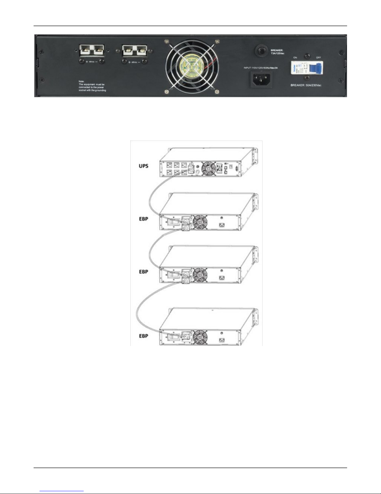
1. Verify that the DC circuit breaker on the rear panel of the CBP is in the OFF posion.
2. Turn the UPS OFF and disconnect the UPS Input Cord from the AC wall outlet.
3. Remove the CBP connector cover from the UPS rear panel.
4. Connect the external DC baery cable from the CBP to the appropriate connector on the UPS.
5. Secure the DC baery cable to both the rear of the UPS and the rear of the CBP by using M3 x 8 screws
provided (2 each per connector end).
6. Repeat the above procedure for tesng and securing each addional CBP required.
CAUTION: Do not use extension cords when connecng input AC power to UPS or CBP’s
7. Move the DC circuit breaker on the rear of each CBP to the ON posion. At this point the UPS will need to
be started.
8. If the CBP’s are plugged into an AC source and properly installed, the internal baeries will be charged
when acceptable voltage is present. CBP’s must be charged for a minimum of 6 hours for full baery me.
NOTE: If the CBP is going to be out of service or stored for six months or longer, the baeries must be
recharged for at least 36 hours every six months.
Charger Baery Pack Q & A
1. Which CBP’s do I connect to an AC input source?
• It is recommended that every third CBP be connected to incoming AC ulity to properly charge the
baeries in a complete system. Leaving too many chargers connected may cause an over charge situ-
aon which could damage the baeries and void the warranty.
2. Which LED’s are supposed to be lit on the front of each CBP?
• When an CBP is connected to an AC input source and the unit is charging, a GREEN LED on the front
of the CBP will be illuminated.
3. Are any LED’s on the front of the CBP supposed to be lit if it is not connected to an AC input source?
• No. The UPS and/or the CBP’s that are plugged into an AC input source are responsible for charging the
enre system. The CBP is sll working and has the capability of providing DC voltage when needed. No
LED on the front bezel will be illuminated.
4. The CBP is connected to an AC input source, why does the LED on the front of the CBP turn ON and OFF
intermiently, and does this mean this CBP is not working?
• The GREEN LED on the front of each CBP indicates that the charger contained in the CBP is charging.
Under certain condions when the baeries are 100% charged, the charger in the CBP will shut o
and the LED will no longer be illuminated. This is normal operaon for the CBP. The CBP is working
properly.
5. Why don’t the LED’s on each CBP connected to an AC input source turn ON and OFF at the same me?
• The charger on each CBP funcons independently from the others. One CBP charger may be charging
while another one might be at 100% and the charger turned o. This is normal operaon of the CBP.
Other manuals for NXRT?1000
1
This manual suits for next models
4
Table of contents