XTRONIC 6040-PRO User manual

X-TRONIC USA
X-TronicTM Model
#6040-PRO
Instructions


- 1 -
PLEASE READ THIS MANUAL BEFORE
USING YOUR NEW X-TRONIC Model
#6040-PRO SOLDERING STATION
This manual is provided to make a safe and effective use of the X-Tronic
6040-PRO soldering station and to maintain this instrument in proper
working condition. Be sure to keep this booklet in a handy place near the
unit for future reference.
SPECIFICATIONS
Model #6040-PRO
Power Consumption ≤ 700 Watts
Voltage AC 110V ± 10% 60Hz
Dimensions 4 x 6 x 5 in
Weight 6.2 lbs
Working Environment 32°F ~ 104°F / 0°C ~ 40°C
Storage Environment -4°F ~ 176°F / -20°C ~ 80°C
Storage Humidity 35% - 45%
Hot Air Rework
Airflow Type Brushless Fan
Airflow ≤ 120 L/min
Temperature Range 212°F ~ 896°F / 100°C ~ 480°C
Temperature Stability ± 2°C
Display Type Digital
Cable Length (Material) ≥ 39.4 in / 100 cm (Silicone)
Noise ≤ 45dB
Soldering Iron
Soldering Iron Power 60W
Temperature Range 392°F ~ 896°F / 200°C ~ 480°C
Temperature Stability ± 1°C
Output Voltage 24 V AC
Tip Impedance < 2Ω
Display Type Digital
Cable Length (Material) ≥ 39.4 in / 100 cm (Silicone)

- 2 -
PANEL DIAGRAM
X-TRONIC PROSeries 6040-PRO
QUICK
PRESS
PRESS
& HOLD
MENU
11
6
5
4
3
2
1
8
9
10
12
13
17
16
15
14
7
1. °C / °F Indicator for Hot Air Gun
2. Hot Air Gun Temperature Display
3. Hot Air Gun Modes
4. Temperature Stabalization Light for
Hot Air Gun
5. Hot Air Gun Quick Conversion
Button
6. Temperature Adjustment Buttons
for Hot Air Gun
7. Air Flow Control Knob
8. Hot Air Gun Power Switch
9. Hot Air Gun Power Receptical
10. Soldering Iron Temperature Display
11. °C / °F Indicator for Soldering Iron
12. Temperature Stabilization Light for
Soldering Iron
13. Calibration mode indicator for both
Soldering Iron and Hot Air Gun
14. Sleep Time Setting for Soldering
Iron
15. Temperature Adjustment Buttons
for Soldering Iron
16. Soldering Iron Power Switch
17. Soldering Iron Power Receptical

- 3 -
INITIAL SET-UP
1. Plug the 3-Prong AC cord into a 110/120V grounded outlet to prevent
electric shock or injury.
2. Turn the power on by pushing the power switch on the back of the
unit. Both LED displays will show “---” and will be blinking.
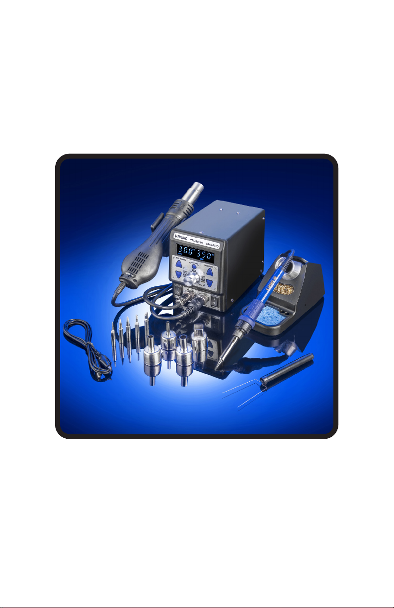
HOT AIR GUN
1. IMPORTANT: Insert the hot air gun into holder on the side of the
unit. If the hot air gun is not mounted in the holder, it cannot be
programmed.
2. Plug the Hot Air Gun into the front power receptacle on the left side
of the unit and tighten the ring nut.
3. Turn on the Hot Air Power Switch on the lower left hand side of the
unit - the LED display will show the last used hot air temperature for
about 2 seconds and then change to “- - -”. This means the hot air
gun is ready to be programmed.
4. Push the blue “Up” or “Down” arrows on the left side of the unit to set
the hot air gun temperature. The temperature will blink to indicate it is
being set. When the temperature has been selected the LED Display
will show “- - -” indicating the hot air gun is now in the Standby State
and set at the programmed temperature.
5. When the hot air gun is removed from the holder it will start blowing
air and ramp up to the programmed temperature in about 8 seconds.
6. When the hot air gun is not in use- set it back in the holster, it will
keep blowing air until the temperature gets back down to 100°C and
then the airflow will stop.
7. When the hot air gun is removed again from the holder it will start
blowing air and ramp up to the programmed temperature in about 8
seconds. This is a safety feature built into the unit.
8. To turn the hot air gun completely off - turn off the power switch on
the left side of the unit.
IMPORTANT: Do not unplug the unit or shut off the Main Power
Switch on the back of the unit until you have placed the hot air gun in
the holder and it has cooled down and shut itself off automatically.

- 4 -
SOLDERING IRON
Note: Before placing the soldering iron in the holder and turning it on,
remove the lid of the rosin flux that sits below the soldering iron tip
when it is in the holder.
1. Plug the Soldering Iron into the front power receptacle on the right
side of the unit and tighten the ring nut. Place the soldering iron in
the soldering iron holder provided.
2. Turn on the soldering iron power switch - the LED display will light
up and show the last temperature that the soldering iron was used at
and begin to heat up to that temperature.
3. To adjust the temperature of the soldering iron, press the blue “Up”
or “Down” arrows on the right side of the unit. The display will blink
indicating that the temperature is being set. When the temperature
has been set, the unit will stop blinking after about 3 seconds and the
soldering iron will start to heat to the newly set temperature.
4. To turn the soldering iron completely off - turn off the power switch.
ADJUSTING AIR FLOW
1. Take the hot air gun out of the holder - it will start heating and
blowing.
2. Adjust the air flow with the Air Flow Control Knob from 20 up to 99.
Important: When using a temperature higher than 300°C on the hot
air gun make sure the air flow is set at 45 or higher. This will prevent
damage to the hot air gun and increase the life of the heating
element.

- 5 -
FUNCTION OPERATIONS
HOT AIR GUN COOL MODE
When the hot air gun is in use, press the airflow control knob quickly
to change the heated air to “COOL” mode. “COOL” will light up on the
screen and the hot air gun will stop heating and the air will drop to room
temperature. To re-activate the heat mode, simply press the airflow
control knob again quickly and the hot air gun will resume heating.
HOT AIR GUN AUTO/MANUAL MODE
When the hot air gun is in its holder on the side of the unit, it will
automatically go into a cool down mode. The hot air gun will continue to
blow air while it cools down to room temperature and then stops blowing
air. When the hot air gun is removed from the holder it will immediately
start the air flow again and heat up to the set temperature. When this
AUTO mode is on, AUTO will display on the screen.
If a project requires you to take it out of AUTO mode briefly, press the
AUTO/MAN button above the airflow control knob and the screen will
change to MANUAL. At this point the hot air gun will start to blow air and
heat up, even if it is in the holder.
NOTE: This unit should ALWAYS be used in Automatic mode for
safety purposes. It is very rare that manual mode is need.
Using Manual mode will also greatly reduce the life of the heating
element in the hot air gun.
SOLDERING IRON SLEEP FUNCTION
When the soldering iron is placed in the holder, the iron will go into
sleep mode after 2 / 10 / 30 minutes (depending on what it is set at).
The display will show “SLP” to signify this and the temperature of the
soldering iron will ramp down to 392°F / 200°C. When the soldering iron
is removed from the holder to use again, the temperature of the soldering
iron will ramp back up to the temperature it was previously being used at
within 5-10 seconds.

- 6 -
SETTING THE SOLDERING IRON SLEEP TIMER
1. Ensure the soldering iron is in the soldering iron holder.
2. Turn on the power switch.
3. Press and hold the aluminum air flow adjustment knob for about
2 seconds. The time options will light up and the option currently
selected will blink.
4. There are four options for how long the unit sits idle until the sleep
timer kicks in:0, 2, 10 or 30 minutes. If you select 0, the unit will
NOT go into sleep mode (this can reduce the life of your soldering
iron and heating element).
5. Adjust the temperature knob to select the sleep time. When
the display indicates the sleep time you would like, press the
airflow adjustment knob two times to save the setting and exit the
programming mode.
TEMPERATURE CONVERSION
1. Ensure the soldering iron and the hot air gun are in their respective
holders.
2. Turn on the power switches.
3. Press and hold the aluminum air flow adjustment knob for about 2
seconds. The sleep time options will light up, the press the knob
one more time.
4. The °C or °F both light up, the one that is currently chosen will blink.
5. Turn the airflow adjustment knob to select either °C or °F.
6. Press the airflow adjustment knob one time to save the setting and
exit the programming mode.

- 7-
TEMPERATURE CALIBRATION
1. Turn on the power switch for either the hot air gun or the soldering
iron, depending on which one you are calibrating.
2. Remove the hot air gun or soldering iron from their holders - they
need to be at the temperature you have set and not in sleep mode.
Note: The temperature for the hot air gun will vary based on the
distance from the source.
3. If the independently measured temperature varies from the
temperature set on the unit, press and hold the “Up” and “Down”
buttons for 2 seconds for the respective device you are calibrating
until the display flashes. “CAL” will light up on the screen and the
temperature being calibrated will flash.
4. Enter the measured temperature into the flashing display by rotating
the airflow adjustment knob.
5. Once the flashing temperature shows the correct temperature,
press the Air Adjustment Knob to save the calibrated temperature
and exit the programming mode.

- 8-
MAINTENANCE
Do NOT put excess pressure on the tip. It can damage the element.
REPLACING SOLDERING IRON TIP
1. Turn off the soldering station, unplug the power cord from the
power source and allow the soldering iron to cool down to room
temperature. Never attempt to remove the tip while the iron is
hot.
2. Unscrew the larger metal tip retaining screw ring at the bottom of
the soldering irons metal shaft. Slide off or remove the soldering tip
retaining collar. Now, remove the tip by sliding it forward.
3. Slide a new tip over the exposed ceramic heating element, slide
the metal retaining collar over the new soldering tip back onto the
soldering iron.
4. Tighten the metal tip retaining screw ring to snug the tip into place.
Do not over tighten the tip retaining screw
5. Plug the soldering iron AC cord into a grounded outlet to resume
soldering.
REPLACING HOT AIR GUN NOZZLE
1. Turn the power off to the unit and unplug it from the power source.
2. Allow the hot air gun and attachment to reach room temperature
before proceeding.
3. Do not use excessive force when inalling/removing hot air
attachments. Loosen the screw and nut from the attachment
by holding the nut with a pair of pliers and turning the screw
counterclockwise.
4. Slide the attachment o of the metallic shaft of the hot air gun.
Repeat in the reverse order for installation. Do not overtighten the screen
and nut on the hot air gun.

- 9-
SE ERROR MESSAGE
When the display shows “SE” this means that the heating element needs
to be replaced. The heating element could be worn out or cracked.
Note: If you run the soldering iron in the 600°F ~ 650°F / 315°C ~ 343°C
range, which is the normal temperature range for most all soldering
applications, the heating element should last for 6 to 12 months
depending on hours of use.
F-1/F-2 ERROR MESSAGE
When the display shows “F-1” or “F-2” this indicates that the fan has
stopped working on the hot air gun and the power supply needs to be
checked.

- 10 -
REPLACING THE HEATING ELEMENT
1. Turn off the unit and unplug it from the outlet.
2. Allow the soldering iron to cool down to room temperature.
Never attempt to remove the tip while the iron is hot.
3. Unscrew the Black “Bakelite Polymer” Retaining Cap and slide off
the full tip assembly.
4. Push the Power Cord through the bottom of the soldering iron while
simultaneously pulling gently on the heating element to expose the
heating element.
5. De-solder the 2 Thin (red or white) wires and the 2 Thick (blue)
wires that have heat shielding on them from the circuit board and
pull the heating element away from the board.
Please take note of the location of the wire thickness/color for
installation of new heating element (see diagram below).
6. On one side of the circuit board solder a thin wire to 1and a thick
wire to 2 (see diagram below).
7. Flip the circuit board over and solder a thin wire to 3and a thick
wire to 4(see diagram below).
8. Pull the cord back gently and align the circuit board to the slots on
the iron so the cord can be pulled back to its original position.
9. Replace Bakelite Polymer Retaining Cap and screw back on and
hand tighten - Do NOT over-tighten.
10. Install the soldering tip, slide the metal soldering tip retaining collar
and hand tighten it. Plug the AC cord back into a grounded outlet.
SIDE A SIDE B
1 2 3 4
NOTE: The wires on the heating element can be soldered back
onto either side of the circuit board, as there is no polarity for the
element.

- 11 -
SOLDERING TIPS PREPARATION & CARE
1. Keep the soldering tip properly tinned. Always use solder with
sufficient rosin flux or the tip will de-wet. A well tinned tip will be bright
all over when hot, with no dull or discolored spots.
2. To tin the iron, do the following:
a. Plug in the iron and allow it to reach solder melt temperature.
b. Flood the tip with solder and let it stand for one minute.
c. Apply more solder to the tip, allow it to idle for one or two more
minutes, wipe it lightly on the sponge. Do not remove all of the
solder, but use the sponge to remove excess solder and wipe
solder onto non-tinned areas.
3. Do not file or attempt to reshape the tip. This will destroy the plating
and shorten tip life. Do not use chloride and acid fluxes; they will also
shorten tip and heater life.
4. For maximum tip life, always apply solder to the heated connections
or joints. Repeated application of solder directly to the tip will
shorten the tip life.
WARNING: Do NOT use anti-seize or any other lubricant on the tip
retainer or heater of the soldering iron.

All X-Tronic Products come with 3-Year Guarantee, valid only in the 48
Contiguous United States. If you purchase this product and ship it to
a destination outside of the 48 Contiguous United States this warranty
becomes null and void. This Guarantee covers the main unit itself.
Consumable parts such as soldering tips, heating elements, nozzles, etc.
are not covered by this warranty.
The first 30 Days are covered by a Money Back or Replacement
Guarantee from the date of the receipt of the product. If your product
becomes damaged in shipment or is found to be defective in any way
during this period, we will replace or issue a complete refund for your
product upon return. We will pay all shipping involved during this first 30-
day period.
The remainder of the 3 Years (after the first 30 days) is covered by a
FREE REPAIR Guarantee (parts and labor included). If anything becomes
defective during this period we will fix the issue and provide a full service
inspection to your product, shipping (to & from) will be paid by the buyer.
Please email us at Info@XTronicUSA.com to set up a service request.
Returns of New/Unused Products
If you have Buyer's Remorse and decide that you do not want the product,
it must be returned NEW & UNUSED in the original box and you will pay
the return shipping. PLEASE NOTE: There will be a 10% Restocking Fee
and original Shipping Costs (if applicable) will not be refunded. Used
product cannot be returned.
3-YEAR WARRANTY
X-Tronic International, Inc.
2159 Magnum Circle, Lincoln, NE 68522
844-861-4762
Info@XTronicUSA.com • www.XTronicUSA.com
How To Register Your Warranty
Go to www.XTronicUSA.com. Click on "Register Your Warranty" tab and
fill out the form. This is a fully secure website. Your information will never
be sold or misused in any way. This registration site is strictly for order
verification that will be used to speed up the process should you ever
need to use your Warranty for service.


QUESTIONS, PROBLEMS
OR COMPLIMENTS?
Thank You for purchasing this
X-Tronic International Product!
We are grateful for your business!
All of our X-Tronic International Products are inspected
then sealed with our NEW Product Seal prior to
shipment. Our goal is to ensure Quality, Completeness,
and Satisfaction for your order.
For Any Questions, Problems, or
Compliments please call or email us.
If you would like to shop for other X-Tronic International Products
Please visit our website
www.XTronicUSA.com
Toll Free: 844-861-4762
Info@XTronicUSA.com
Our Business Hours are:
Monday - Thursday: 8am - 4pm CST
Friday: 8am - Noon CST
Table of contents
Other XTRONIC Ultrasonic Jewelry Cleaner manuals
Popular Ultrasonic Jewelry Cleaner manuals by other brands

Silvercrest
Silvercrest SHBR 560 B1 operating instructions

KirmussAudio
KirmussAudio KA-RC-1 owner's manual

Prochem
Prochem EVEREST 650 operating instructions

Supco
Supco RLE202 quick start guide

Kärcher
Kärcher T 150 T-Racer quick start guide

Flexco
Flexco H-Type Primary Cleaner with V-Tips Installation, operation and maintenance manual