Yaesu ZCUT-870 User manual

AUTO TAPE DISPENSER
ZCUT-870
INSTRUCTION MANUAL

2
P 2 Before Use
P 3 Safety Instructions
P 3-5 Definition of Warning and Caution Symbols
P 6 Identification of Parts
P 7 Loading the Tape
P 8 Setting the Tape Length and Cut-Piece Spacing
P 8-9 Setting the Mode
P 10 Dealing with Curling Tape
P 10 Maintenance
P 10 Our Recommendation
P 11 Replacing the Upper and Lower Blades
P 12 Specifications
P 12 Warranty
Contents
Before Use
Thank you for buying Auto Tape Dispenser model ZCUT-870.
ZCUT-870 is a compact, unique feeding system which allows to many
kinds of tape, includes minimum size of thin tapes.
Please read this Instruction Manual carefully.
For your safety, please keep this Instruction Manual for reference,
retraining and trouble shooting.

3
The safety guidelines in this Instruction Manual must be observed in order
to prevent damage to the machine or injury to the operator or other person.
The safety guidelines prescribed "Warning " and "Caution" describe possib-
le injury or damage that may be suffered from operating or maintaining the
machine in a manner other than as described in this Instruction Manual.
Read and follow the safety precautions carefully before reading the Instruc-
tion Manual.
Indicates a potentially hazardous situation which
if not avoided, could result in death or serious injury.
Indicate that carelessness of handling may result in
danger and that the operator is at risk of injury,
or the machine is at risk of damage.
Indicates Caution
A symbol within the triangle, or the description,
will indicate a specific hazard.
A Prohibited Action
A symbol within the circle, or with a diagonal stroke,
will indicate prohibited action.
A Required Action
A symbol within the circle in black, or the description,
will indicate the required action.
Definition of Warning Symbols
Warning
Caution
Safety Instructions

4
Warning
Do not plug in, unplug the cord, or operate the machine with wet
hands.
Failure to observe this may result in injury due to electric shocks.
Never insert your finger, or any other body part, or any foreign
object into the machine.
Failure to observe this may result in injury.
Keep hair or loose clothing away from the machine while it is
operating.
Failure to observe this may result in injury.
This machine is intended for industrial use only.
Do not allow untrained operators or children to operate the machine.
Failure to observe this may result in injury.
Turn off the power switch and unplug machine prior to replacing
the blade or performing any maintenance the machine.
Failure to observe this may result in serious injury.
Do not use this machine for anything other that its specified
applications.
Use of the machine for any unintended applications can cause
injury to the operator or failure of the machine.

Do not expose the machine to water or other liquids.
Do not install or use the machine where it may come into contact
with water or other liquids.
Exposure to water or other liquid cam cause injury due to electric
shock, or failure of the machine.
Never modify or disassemble the machine.
This can cause injury or failure of the machine.
Always unplug, or the machine in, by holding the plug.
Never pull on the cord.
Pulling on the cord can result in an injury due electric shock.
Never place foreign object into the machine.
This can cause failure of the machine.
An operators presence is required whenever the machine in
operation.
Turn the machine off and unplug the cord when the operator is not
present.
Failure to observe this can result injury.
Do not cut or damage the power cord.
A cut or damage the cord can lead to electric shock, a short circuit
or possible fire hazard.
Make sure the cord is connected properly to the electrical outlet as
well as the receptacle on the back of the machine.
A loose connection can result in high heat or fire.
Do not use the machine in areas where moisture is present, high
temperatures exist or a high content of dust or dirt is present.
This can result in failure of the machine.
Always install and operate the machine on a flat, stable surface.
Dropping the machine can lead to failure of the machine or injury
to the operator.
Always remove the tape from the machine when you are finished
with the operation.
Leaving the tape in the machine may lead to a build up of adhesive
on the part, or cause the tape curl.
Caution
5

6
Cutter Blade Arm
Power Switch
Lower Blade Stopper
Upper Blade Start Button
Turn Table
Tape Holder Adjustment Lever
Tape Holder
Tape Holder
Tape Support Bar
Fuse Holder
Brake Roller
Roller Lock Lever
Support Stand
Length Adjustment Knob
Cut-Piece Spacing Knob
Slit
Lower Blade
Safety Cover
Movable Sensor
Release Button
I dentif ication of P arts

7
Start Button
Tape Holder Adjustment Lever
Tape Support Bar
Brake Roller
Slit
Turn Table
Loading the Tape
Make sure to turn the POWER
SWITCH off, and according to
Instruction Manual when you set
the tape.
WARNING: Whenever you set
the tape, do not touch the
UPPER and LOWER BLADES.
■Make sure the SUPPORT STAND in use.
■Make sure the POWER SWITCH is off and plug in.
■Turn the POWER SWITCH ON.
( A lightly beep sound will come out then the START BUTTON lights
and shows the mode color. )
( The default on this tape dispenser sets number of cut. Red color
light on which means 2 pcs. is set. )
■Slide SAFETY COVER to the direction of OPEN to open SAFETY
COVER.
( The START BUTTON is flashing with Red light. )
■Press the START BUTTON and move the CUTTER BLADE ARM
little by little.
( Catch the timing where the cutter blades open most widely. )
( Press the START BUTTON continuously, the CUTTER BLADE
ARM moves intermittently. )
■Turn the POWER SWITCH OFF.
■Plug the cord out.
■Pull the TAPE SUPPORT BAR out to the limit.
■Pull the tape under the BRAKE ROLLER.
■Put the tape between the TAPE HOLDER, hooked by TAPE
SUPPORT BAR and through the SLIT (between UPPER and
LOWER BLADE) and affix the tape to the TURN TABLE.
■Adjust the TAPE HOLDER to the proper width by sliding the TAPE
HOLDER ADJUSTMENT LEVER.
■Slide SAFETY COVER to the direction of CLOSE to close SAFETY
COVER.
■Plug in the cord.
■Turn the POWER SWITCH ON.
■Press the START BUTTON.
( When you use AUTO MODE A (Blue light on) or AUTO MODE B
(Purple light on), stop rotating the TURN TABLE at the SENSOR
which you set. When you use PRESET MODE (Red light on), the
TURN TABLE stop rotating after finishing numbers of cut. )

S etting the T ape Length and C u t- P iece S pacing
You can adjust the length and cut-piece spacing
whether Z CUT-87 0 is "ON" or "OFF".
■Turn the LENGTH ADJUSTMENT KNOB to the desired tape length.
(The number which is pointed in approx imate Millimeter.)
(The actual length differs from the shown length depends on the type
of tape and its condition.)
■Turn CUT-PIECE SPACING KNOB to the desired spacing.
(Make sure to keep the proper space between the cuts to avoid
tape overlapping.)
8
S etting the M ode
Cut-Piece Spacing Knob
Length Adjustment Knob
As depend on the terms of use, please select from different kinds of mode.
In the case of following changes,Sensor Mode ASensor Mode BPreset ModeSetting
the Blade Close Mode, please press the START BUTTON longer until buzze r sounds.
The START BUTTON should be pressed longer when you prefer setting the blade close mode.
When you prefer setting the blade open mode, you just press the START BUTTON shorter.
(Even for setting the blade open mode, buzze r will sound.)
Setting the blade close mode will be available for all setting the mode of Sensor Mode A,
Sensor Mode B, and Preset Mode.
If power switch turns on while pressing the START BUTTON, you will be able to set the number
of cut as you desire.
Please refer to the illustration as below.
Setting the Blade Close Mode
■Press the START BUTTON longer and setting the blade close mode will be done.
■Setting the blade close mode means both upper blade and lower blade are closed when the cutting
blade stops. Press the START BUTTON longer if you prefer this mode. This mode will be suitable
for cutting the ext endible tapes.
■Setting the blade open mode means both upper blade and lower blade are opened when the cutting
blade stops. Press the START BUTTON shorter if you prefer this mode.
■When power switch turns on, the cutting blade will remain opened.
SENSOR MODE A
(Blue light is on)
SENSOR MODE B
(Purple light is on)
PRESET MODE
(Red light is on)
POWER SWITCH ON
START BUTTON
Setting the number
of cut
Press shorter (Blade stops and opens)
Press longer (Blade stops and closes)
Setting the Blade Close Mode
(Purple light is flashing)

9
ZCUT-870 is able to be programmed.
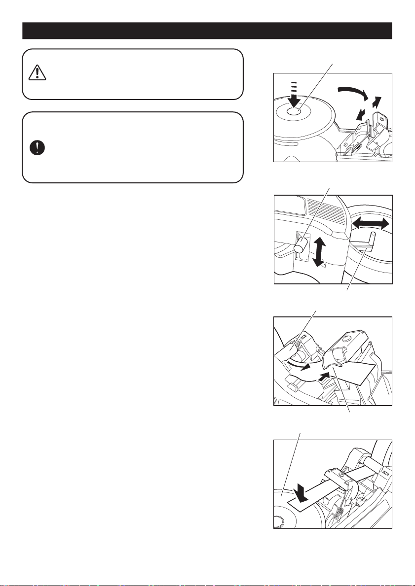
■Turn the POWER SWITCH off.
■During pressing the START BUTTON, turn the POWER SWITCH on in a same time.
■When the beep sound come, leave your finger from the START BUTTON.
(Confirm the beep sound comes again, and START BUTTON is flashing in Red and Bluealternately.)
■Press the START BUTTON and set the desired the number of cut minus two.
(For example, if you want to set 10 pieces, you should press the START BUTTON eight times.
Maximum set number of cut is 15 pieces.)
■When you set the number of cut, press the START BUTTON longer until beep sound comes.
■Make sure the START BUTTON light turned Red.
■Press the START BUTTON and start to operate.
(The machine will stop cutting when reach the number of cut which you set.)
(After turn the POWER SWITCH off, the number of cut is still memorized.)
(When you stop the machine during operation, press the START BUTTON.
At this moment, the machine has already reset the number of cut.)
(Press START BUTTON again for re-start.)
SENSOR MODE A SENSOR MODE B PRESET MODE
PRESET MODE
Stop after cut
Press Start Button for Re-Start
Remove the tape
Remove the tape
Re-Start automatically
Start
Start
Start
RedPurpleBlue
Stop
Stop
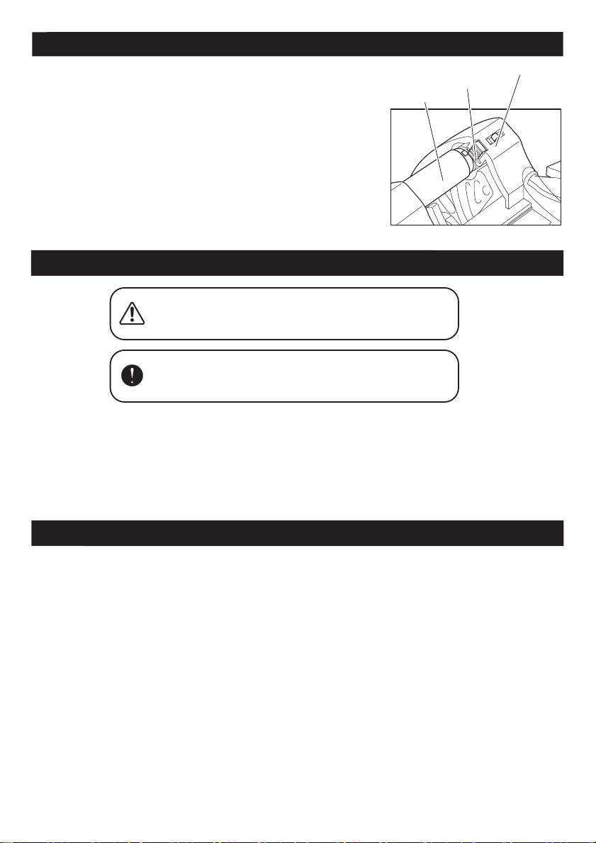
■Press the START BUTTON longer. (Purple light is on)
■Move the MOVABLE SENSOR to the desired position.
■Press the START BUTTON then start.
■When the tape reach over the MOVABLE SENSOR, machine will stop cutting.
(If the machine can not stop cutting to pass through the MOVABLE SENSOR, check and adjust the
position of MOVABLE SENSOR again.)
■When you remove the tape from the TURN TABLE, press the START BUTTON again.
■When the tape reach over the MOVABLE SENSOR, the machine will stop cutting.
■Press the START BUTTON longer. (Blue light is on)
■Move the MOVABLE SENSOR to the desired position.
■Press the START BUTTON then start.
■When the tape reach over the MOVABLE SENSOR, machine will stop cutting.
(If the machine can not stop cutting to pass through the MOVABLE SENSOR, check and adjust the
position of MOVABLE SENSOR again.)
■When you remove the tape over the MOVABLE SENSOR, machine will start to cut again automatically.
SENSOR MODE A
SENSOR MODE B

10
10
Maintenance
■If you have been using ZCUT-870 for a long time, tape residue starts to stick on the blades, and it
becomes harder to cut. Remove tape residue with alcohol.
■Check the screw of UPPER BLADE regularly.
If the screw is loosen, ZCUT-870 can not cut the tape properly.
■If the tape can not stick on the TURN TABLE, clean the TURN TABLE by using alcohol with a clean dry
cloth, or swab remove the residue.
When performing any maintenance,
make sure ZCUT-870 is "OFF".
■When you carry ZCUT-870, please hold the bottom of machine.
Do not grab the TURN TABLE.
■Make sure the POWER SWITCH is "OFF" when you set the tape.
■Please follow the instructions when you set the tape.
(If you can not make it, read Instruction Manual carefully and do it over from the beginning.)
■When ZCUT-870 is not in use, please unplug and switch OFF the POWER SWITCH.
■When you finish using ZCUT-870, remove all the tape from the TURN TABLE.
■Please do not modify ZCUT-870 by yourself.
■ZCUT-870 is designed for tape cutting only. Please do not cut any other things.
■ZCUT-870 is designed for industrial use.
(It is not recommended to use at home. Do not use around children.)
■During the operation, if ZCUT-870 stops suddenly or make strange noise, please stop using ZCUT-870
immediately and send it back to us for checking or repairing.
■If ZCUT-870 is broken, please send it to us with the existing tape that you have been used.
■If you have any questions about your using tape, please contact us and send a sample roll for evaluation.
Our Recommendation
Warning: The BLADES are very sharp.
Do not touch the BLADES by hand.
■Press the ROLLER LOCK LEVER inward.
■Turn the BRAKE ROLLER until can not turn.
(With the roller locked the tension may cause the length to vary.)
(Cut several sample pieces and adjust the length if you needed.)
(Press the RELEASE BUTTON when you need to release the lock.)
Dealing with Curling Tape
Roller Lock Lever
Release Button
Brake Roller

11
①
⑤
②
③
④
Before replacing the blades, make sure
the POWER SWITCH is "OFF".
WARNING: The blades are very sharp.
Whenever replace the blades, do not
touch the blades and use pliers.
The blades are consumable, and they will eventually
worn out.
If it happens, please replace a new one.
The staying power of blades are based on the tape's
quality, material, thickness which you are using.
Replacing the Upper and Lower Blades
Lower Blade Stopper
Upper Blade
Lower Blade
Lower Blade
Screw
Lower Blade Press
Lower Blade Press
Slider
Fulcrum
Projection
Press the Lower Blade Press
Insert the Slider's pin to
the oval shape hole
How to Remove the UPPER BLADE
How to Remove the LOWER BLADE
How to Replace the LOWER BLADE
■Turn the POWER SWITCH off and unplug the cord.
■Slide SAFETY COVER to the direction of OPEN to open SAFETY
COVER.
■Take the screw out of the UPPER BLADE.
■Replace the new blade.
■Make sure that SAFETY COVER is definitely closed after setting
tape.
■Plug in the cord and turn the POWER SWITCH on and test to cut.
■Turn the POWER SWITCH off and unplug the cord.
■Slide SAFETY COVER to the direction of OPEN to open SAFETY
COVER.
■For easy remove, turn the LENGTH ADJUSTMENT KNOB to the
limit.
■Press the LOWER BLADE PRESS and raise the LOWER BLADE
STOPPER. [①-②]
■Hold the projection of right side of the LOWER BLADE by pliers. [③]
■Turn 180 degrees to the left and take the LOWER BLADE out from
the fulcrum. [④]
■Put the LOWER BLADE back to fulcrum.
■Turn the LOWER BLADE until the SLIDER's pin can insert the oval
shape hole of the LOWER BLADE. [⑤]
■Pull the LOWER BLADE STOPPER down.
(If the blades are not set properly, the machine is at risk of damege.)
■Make sure that SAFETY COVER is definitely closed after setting
tape.
■Plug in the cord and turn the POWER SWITCH on then test to cut.

Power Requirements 100VAC 50/60Hz
120VAC 50/60Hz 25W
220-240VAC 50/60Hz
Input Voltage range ±5%
Fuse 2 A
Dimensions 126 W x150 H x258 D(mm)
Weight 1.9 kg
Body Material ABS
Tape Length 15 - 70 mm
Tape Width 3 - 25 mm
Outside Dia. of Roll Φ150
The specifications are subject to change without prior notice.
The length of tape may differ from the set length depending upon the type of tape or its condition.
Some types of tape available with the machine may not be cut depending upon conditions.
12
Warranty
YAESU KEIKOGYO CO., LTD.
39-8, Senju Motomachi, Adachi-Ku,
Tokyo, 120-0041, Japan
Phone 81-3-3888-8751
Fax 81-3-3888-1592
URL http://www.yaesu1965.com
Specifications
All parts on ZCUT-870 auto tape dispenser against defects in design, materials, and
workmanship are under warranty for a period of 180 days.
Parts excluded from the above mentioned is cutting blades, as these part is considered
as a "wear parts".
Warranty repair is contingent upon our examination and determination that alleged
defects have not been caused by misuse, abuse, improper installation or application,
repair, alternation, accident or neglect in use, storage, transportation, or handling.
15i18
Table of contents
Other Yaesu Dispenser manuals
Popular Dispenser manuals by other brands

IEI Technology
IEI Technology ACCURA9 instruction manual

Miele professional
Miele professional DOS-Modul G 60 Fitting instructions

Coca-Cola
Coca-Cola freestyle 3100 user guide

OK International
OK International DX-350 / 355 user guide

acaia
acaia Orion Mini Bean Doser user manual

DIMA
DIMA 943 Assembly instructions