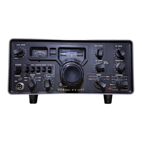
Yaesu FT-223 User manual

INSTRUCTION
MANUAL
FT-223
Y
AESU
MUSEN
CO.,
LTD.
TOKYO
JAPAN

TABLE
OF
CONTENTS
GENERAL
Page
1
SPECIFICATIONS
Page
4
INSTALLATION
-
General
Page
5
-
Mobile
Installation
Page
6
-
Base
Station
Installation
Page
8
CONTROLS
&
SWITCHES
Page
8
REAR
PANEL
CONNECTIONS
Page
10
OPERATION
Page
11
THEORY
OF
OPERATION
-
General
Page
12
-
Transmitter
Section
Page
12
-
Receiver
Section
Page
14
-
Tone
Burst
Circuit
Page
16
-
Tone
Squelch
Circuit
(Optional)
Page
16
MAINTENANCE
---=
-
General
Page
18
-
Routine
Maintenance
Page
19
-
Adjustments
Page
20
-
Expanding
Channel
Capabilities
Page
24
-
Trouble
-shooting
Page
26
RESISTANCE/VOLTAGE
CHARTS
Page
27
PARTS
LIST
Page
28

FT-223
2
METER
FM
TRANSCEIVER
GENERAL
The
model
FT-223
is
a
compact
transceiver
specifically
designed
to
provide
high
performance
for
amateur
VHF
/FM
service.
The
transceiver
is
completely
solid
state
with
provision
for
operation
of
up
to
23
crystal
controlled
channels
between
144
and
148
MHz.
The
advanced
circuit
design
features
prevent
damage
to
the
transistors
in
case
of
high
antenna
VSWR,
or
reversed
power
supply
polarity,
while
an
adjustable
"tone-burst"
generator
is
included
for
repeater
actuation.
An
additional
feature,
is
an
optional
tone
squelch
circuit
for
a
selective
calling
system.
The
heavy
gauge
metal
case
provides
an
extremely
rugged
package,
light
in
weight,
yet
virtually
immune
to
the
effects
of
shock
and
vibration.
The
FT-223
VHF
/FM
transceiver
is
supplied
complete
with
all
mounting
hardware,
cables,
connectors
and
accessories
required
for
a
mobile
installation,
as
shown
in
Figure
1.
- 1 -

CD
®
®
(J)
®
Figure
1.
1.
Transceiver
with
built-in
3
11
speaker
(3
channels
factory
installed).
2.
Dynamic
push-to-talk
microphone
with
retractable
coiled
cord.
3.
Universal
mounting
bracket
(with
screws,
washers
and
nuts).
4.
Power
cable
(with
cigarette
lighter
adapter).
5.
Spare
£uses.
6.
Microphone
hanger.
7.
Miniature
phone
plug
for
external
speaker.
8.
Alignment
tool.
9.
Tap
connector.
- 2 -

HOW
TO
USE
THE
TAP
CONNECTOR
Do
NOT
strip
i~
lation
from
wires.
1.
2.
3.
4.
5.
6.
The
tap
connector
will
handle
most
wire
sizes
used
in
automotive
instrument
panels.
Slide
the
"hot"
lead
into
tap
connector
as
shown.
Insert
transceiver
power
lead
3
/4
of
the
way
into
connector
(just
past
metal
connector
element).
Using
pliers,
press
the
metal
connector
element
until
it
is
FLUSH.
Fold
the
hinged
cover
over
the
connector
element
and
snap
firmly
in
place.
PLASTIC
INSULATOR
WITH
HINGED
"SNAP-IN''
COVER
CONNECTION
MADE
WITH
ANY
PLIERS
TYPE
TOOL
BY
DRIVING
ELEMENT
OVER
WIRES
_POWER
TO
TRANSCEIVER
SLOT
FOR
SIDE
ENTRY
OF
"HOT"
WIRE
Figure
2
- 3 -
~WIRES
SELF-STRIPPING
''U''
TYPE
SPRING
PRESSURE
CONNECTOR
ELEMENT

The
compact
design
of
the
FT-223
transceiver
makes
it
ideal
for
mobile
installation,
operating
directly
from
the
vehicle
's
12
Volt
battery.
For
base
station
use,
an
accessory
model
,
FP-2
Two-Way
Power
Supply,
provides
operating
voltage
plus
a
large
external
speaker.
SPECIFICATIONS
GENERAL
Frequency
Coverage
Number
of
Channels
Speaker
Microphone
Power
Requirement
Current
Consumption
Metering
Dimensions
Weight
TRANSMITTER
RF
Output
Frequency
Stability
Crystal
Multiplication
Modulation
Deviation
- 4 -
144
to
146
MHz
or
146
to
148
MHz
23
(3
channels
supplied)
an
optional
external
VFO
can
be
used
Internal
3
11
dynamic
speaker
with
provision
for
connecting
external
4
ohm
dynamic
speaker
Dynamic
push-to-talk
microphone
with
retractable
coiled
cord
13.
5
Volts
DC,
+10%
0.
45
Amp
receive
1.
2
Amp
transmit
(LOW)
2.
3
Amp
transmit
(HI)
Illuminated
front
panel
meter
indicates
relative
received
signal
strength
and
transmitter
power
output
180
(W)
x
60
(H) x
220
(D)
mm
2.
5
Kg
10
Watts
(HI)
or
1
Watt
(LOW)
into
50
ohm
load
at
13.
5
Volts
DC
+0.002%
12
times
F3
(phase
modulation)
Up
to
±_10
kHz
(factory
adjusted
at
+5
kHz)

Audio
Response
Spurious
Emissions
Tone
Burst
RECEIVER
Type
Intermediate
Frequency
Sensitivity
Selectivity
Audio
Output
+
1,
-3
dB
of
6
dB
/
Octave
pre
-emphasis
characteristic
from
300
to
2500
Hz
60
dB
below
carrier
minimum
Nominally
one
second
at
1800
Hz
(adjustable
between
1300
&
3000
Hz)
Double
conversion
superheterodyne
(
crystal
controlled)
10.
7
MHz
first
IF;
455
kHz
second
IF
-4
dB
for
20
dB
quieting
±_6
kHz
at
6
dB;
+
12
kHz
at
60
dB
2
Watts
at
4
ohms
INSTALLATION
GENERAL
The
model
FT-223
transceiver
is
designed
primarily
for
mobile
service,
requiring
only
an
antenna
and
a
13.
5
Volts
DC
power
source
for
operation.
However,
when
operated
in
conjunction
with
model
FP-2
Two-Way
Power
Supply,
the
transceiver
provides
an
efficient
compact
base
station.
The
FP
- 2
power
supply
provides
13.
5
Volts
DC
to
operate
the
transceiver
from
an
AC
power
source.
The
transceiver
has
been
factory
pre-tuned
and
requires
no
adjustments
for
normal
operation
into
a
50
ohm
load.
The
antenna
location
is
the
most
important
consideration
in
either
a
base
or
mobile
installation,
with
effective
communication
range
directly
related
to
antenna
height.
The
antenna
should
always
be
in
the
clear
and
as
high
as
possible,
however,
a
minimum
distance
of
5
feet
should
be
maintained
between
the
VHF
and
other
antennas.
Also,
in
mobile
installation,
it
is
advisable
to
locate
the
antenna
as
far
from
the
engine
as
practical,
in
order
to
minimize
ignition
noise
pick-up.
In
all
installations
ensure
that
the
antenna
VSWR
is
less
than
1.5:1.
For
mobile
installation,
the
most
popular
antenna
types
are
either
a 1
/4
wave
whip
with
unity
gain,
or
a 5 / 8
wave
affording
approximately
3.
5
dB
gain.
Mobile
antennas
are
available
from
most
dealers
who
handle
two-way
mobile
radip
equipment,
or
other
local
electronic
suppliers.
- 5 -

To
minimize
losses
in
the
antenna
system,
use
the
shortest
length
of
coaxial
cable
that
is
practical,
avoiding
any
sharp
angles
or
kinks.
Use
type
RG-8
/U
cable
if
the
transmission
line
length
exceeds
25
feet,
while
RG-58
/U
is
suitable
for
shorter
lengths.
For
all
bends,
form
the
cable
into
a
radius
not
less
than
10
times
its
diameter.
MOBILE
INSTALLATION
In
mobile
service
the
FT-223
should
be
installed
where
the
controls,
indicators,
and
microphone
are
easily
visible
and
accessible
for
operation.
The
unit
may
be
mounted
in
any
position
without
loss
of
performance
.
.Suitable
locations
are
under
the
dash,
atop
the
transmission
tunnel,
etc.
A
universal
bracket
is
supplied
with
the
transceiver
for
this
purpose.
Install
the
FT-223
as
follows
(
refer
to
Figure
3):
1.
Use
the
universal
mounting
bracket
as
a
template
to
locate
the
mounting
holes.
Use
a 3 /
16"
diameter
drill
for
these
holes
and
allow
clearance
for
the
transceiver,
its
controls
and
the
connecting
cables.
Secure
the
mounting
bracket
with
the
screws,
washers
and
nuts
supplied
as
shown
in
"3A
11
,
Figure
3A.
2.
Install
the
transceiver
in
the
mounting
bracket,
securing
with
the
four
knurled
head
screws
and
washers
as
shown
in
11
3B
11
,
Figure
3B.
- 6 -

Figure
3C
4.
The
supplied
power
cable
may
be
plugged
directly
into
the
vehicle
Is
cigarette
lighter
receptacle
for
casual
operation
if
desired.
For
a
permanent
installation,
the
lighter
plug
may
be
removed
and
the
leads
routed
directly
to
the
battery
(
red
positive,
black
negative
or
ground),
or
the
nearest
termination
to
the
battery;
i.e.
ignition
switch,
fuse
block,
etc.
If
it
is
necessary
to
extend
the
power
leads,
use
#16
AWG
insulated
copper
wire
and
do
not
extend
the
leads
further
than
required
to
prevent
excessive
voltage
drop.
CAUTION
--------------
--------------
Before
connecting
the
power
cable
to
the
transceiver,
check
the
battery
voltage
with
the
engine
running
(battery
charging).
If
the
voltage
exceeds
14
Volts
DC,
the
regulator
should
be
readjusted
so
the
highest
charging
rate
does
not
exceed
14
Volts.
Also,
be
sure
to
observe
proper
polarity
when
making
battery
connections
(
reversed
polarity
will
not
damage
the
FT-223
due
to
the
protective
circuitry
incorporated
in
the
design,
however,
the
equipment
will
not
operate
under
this
condition).
- 7 -

5.
Connect
the
power
cable
to
the
POWER
receptacle
on
the
rear
panel.
6.
Connect
the
50
ohm
antenna
cable
to
the
ANT
receptacle
on
the
rear
panel.
7.
Connect
the
microphone
cable
to
the
4-pin
microphone
receptacle
on
the
front
panel.
8.
An
external
4
ohm
speaker
may
be
connected
at
the
SP
receptacle
on
the
rear
panel
if
desired
(this
automatically
disconnects
the
internal
speaker).
Use
the
external
speaker
plug
supplied.
BASE
STATION
INSTALLATION
As
a
base
station,
the
FT-223
requires
a
source
of
13.
5
Volts
DC
at
2.
6
amperes.
This
source
may
be
obtained
from
the
accessory,
FP-2
power
supply.
CONTROLS
&
SWITCHES
The
FT-223
VHF
/
FM
transceiver
has
been
designed
for
ease
of
operation.
Be
sure
you
thoroughly
understand
the
function
of
each
control
and
indicator
before
operating
the
equipment.
The
operating
functions
are
as
follows.
FT-223
VHF
/FM
TRANSCEIVER
Figure
4.
- 8 -

1.
VOLUME
Control
2.
SQUELCH
(SQL)
Control
3.
CHANNEL
Selector
4.
CHANNEL
Indicator
5.
CALL
Switch
6.
HI-LOW
Switch
7.
Microphone
Receptacle
8.
IND
I
CA
TORS
-
ON
AIR
CALL
LOW
BUSY
The
VOLUME
control
adjusts
the
receiver
audio
output
level
(applies
power
when
pushed
in).
The
SQUELCH
control
adjusts
the
receiver
squelch
threshold
sensitivity.
An
optional
tone
squelch
circuit
is
activated
when
rotated
to
the
extreme
CCW
position
marked
TONE.
The
23
position
CHANNEL
selector
switch
selects
the
desired
qperating
channel.
The
channel
indicator
shows
the
selected
operating
channel
(illuminated
when
power
is
applied).
When
depressed,
the
CALL
switch
selects
a
preset
channel
regardless
of
the
CHANNEL
selector
switch
position
and
CALL
lamp
lights
up.
The
HI-LOW
switch
selects
the
desired
power
output,
10
watts
in
HI
position,
or
1
watt
in
LOW
position.
In
LOW
position,
LOW
lamp
lights
up.
Four-pin
connector
is
used
for
microphone
input
and
push-to
-talk
relay
actuation.
The
red
lamp
lights
up
in
the
irtransmit''
mode.
The
red
lamp
lights
up
when
the
CALL
channel
is
selected.
The
red
lamp
lights
up
when
the
transceiver
is
operated
at
LOW
power.
The
red
lamp
lights
up
when
the
signal
is
received.
- 9 -

®
REAR
PANEL
1.
POWER
Receptacle
2.
SP
Receptacle
3.
ANT
Receptacle
4.
BURST
Switch
5.
ACC
Socket
TX UNIT
(PB-1
537)
RX
UNIT
(PB-1538)
CD
Figure
5
Two
-pin
connector
is
used
for
connection
to
13.
5
Volts
DC
(negative
ground)
power
source,
vehicle
batter
y ,
or
FP-2
power
supply.
Audio
output
is
provided
at
this
receptacle
for
an
external
speaker
(or
speaker
in
FP-2
power
supply).
Output
impedance
is
4
ohms
and
the
internal
speaker
will
be
disabled
when
a
plug
is
inserted.
UHF
type
coaxial
receptacle
for
connection
of
antenna.
The
BURST
switch
applies
a
short
"tone
burst"
to
the
carrier
at
the
start
of
each
transmission
in
the
"ON"
position.
This
is
normally
used
only
with
"tone
access"
repeater
operation.
The
ACCESSORY
socket
is
used
for
external
VFO
operation.
Figure
6
-
10
-

OPERATION
OPERATING
PROCEDURE
1.
Push
the
VOLUME
control
switch
to
apply
power.
The
channel
indicator
and
meter
will
illuminate.
2.
Set
the
CHANNEL
selector
to
the
de
sired
channel
as
shown
in
the
channel
indicator
window.
Ensure
that
the
CALL
switch
is
at
"OFF"
position.
When
the
CALL
switch
is
in
the
"ON''
position,
the
preset
channel
is
selected
regardless
of
the
CHANNEL
selector
switch
position.
For
preset
channel
operation,
set
the
CALL
switch
to
"CALL"
position.
3.
Rotate
the
SQUELCH
control
fully
counter-clockwise
to
TONE
position
and
slightly
rotate
clockwise
beyond
TONE
position.
For
selective
calling
position,
set
the
SQL
control
to
TONE
position.
4.
Adjust
the
VOLUME
control
for
a
normal
listening
le
v
el
(background
noise
or
a
station
if
one
is
transmitting).
5.
When
the
channel
is
clear
(background
noise
only),
rotate
the
SQUELCH
control
clockwise
until
the
receiver
is
silenced.
Perform
this
step
carefully
so
as
not
to
go
beyond
the
silencing
point
or
the
receiver
will
not
respond
to
weak
signals.
6.
Set
the
HI-LOW
switch
to
the
desired
power
output
position.
7.
If
operating
on
a
repeater
channel
requiring
"tone
access",
set
the
BURST
switch
on
the
rear
panel
to
the
"ON"
position.
The
"tone
burst"
will
be
applied
to
the
carrier
each
time
the
push-to-talk
lever
on
the
microphone
is
depressed
.
NOTE:
Refer
to
the
Tone
Adjustments
paragraph
to
change
the
tone
frequency
or
duration
(factory
set
for
1800
Hz
and
one
second).
8.
When
ready
to
transmit,
hold
the
microphone
close
to
your
mouth,
depress
the
push-to
-talk
lever
and
speak
distinctly
at
a
normal
conversational
level.
Check
that
the
red
"transmit"
indicator
illuminates
and
the
meter
indicates
upward.
-11
-

J
THEORY
OF
OPERATION
GENERAL
Functional
operation
of
the
model
FT-223
VHF
/
FM
transceiver
is
illustrated
in
the
Block
Diagram,
Figure
6
Refer
to
the
schematic
diagram
for
the
circuit
description.
The
transceiver
consists
of
a
crystal
controlled
transmitter
and
receiver
operating
on
any
of
the
23
channels
within
the
frequency
range
of
144
to
148
MHz.
In
addition
to
22
channels
which
are
selected
by
the
CHANNEL
selector
switch,
one
11
most-often-used
11
channel
may
be
preset
for
ease
of
operation.
Solid
state
circuitry
is
employed
throughout
and
the
transceiver
is
designed
to
operate
from
a
13.
5
Volt
+10%
DC
negative
ground
power
source.
TRANSMITTER
SECTION
The
transmitter
section
produces
an
FM
(phase
modulation
method)
output
signal.
The
audio
signal
froro.
the
microphone
is
amplified
by
an
integrated
circuit
Q201
(TA7061AP)
which
works
as
amplifier
and
an
IDC
(Instantaneous
Deviation
Control)
circuit.
The
IDC
circuit,
clips
both
positive
and
negative
peaks
when
they
exceed
a
predetermined
level
to
limit
the
maximum
deviation
of
the
transmitter.
The
IDC
control,
VR202,
permits
the
deviation
to
be
adjusted,
and
is
nominally
factory
set
for
a
deviation
of
+5
kHz.
When
wide
band
transmission
is
desired,
VR202
must
be
readjusted
to
provide
a
maximum
deviation
of
+10
kHz.
FT-223
BLOCK
DIAGRAM
c::J ' 1
T
L-------------,
(
PB
- 1
537)
TX
& - - I
METER
I
~.?L
__
-----
--__
--
_
L___
_
___
_
.J::-=-=-=
-
--::
--===
=--====;r
---
-___j
,__
_ _
______
____
___
_
Figure
6
-
12
-
RECEI VE
T
RANSMIT
CON
TROL

The
limited
audio
signal
is
applied
through
a
low-pass
filter
to
Q202,
2SC372Y
where
it
is
amplified
and
applied
to
the
phase
modulator,
varactor
diode
D201,
1S1658.
The
low-
;
pass
filter
limits
the
transmitter
modulation
spectrum
by
attenuating
frequencies
above
the
speech
range.
The
oscillator,
Q203,
2SC372Y,
operates
on
the
crystal
frequency
to
generate
the
initial
RF
signal.
The
crystal
frequency
is
in
the
12
MHz
range,
and
is
determined
as
follows:
Crystal
Frequency
(MHz)
=
Output
Frequency
(MHz)
12
Trimmer
capacitors
TC401
through
TC423
permit
each
of
the
23
crystals
to
be
individually
set
to
frequency.
Output
from
Q203
is
amplified
by
Q204,
2SC372Y,
and
applied
across
transformer
L203.
The
audio
signal
from
Q202
varies
the
bias
applied
to
D201
and
D202,
in
turn
causing
the
capacity
of
the
diodes
to
vary
in
accordance
with
the
audio
voltage.
As
D201
and
T201
and
D202
and
T202
are
in
series,
the
capacity
change
in
the
diode
effectively
changes
the
resonant
frequency
to
produce
a
phase
shift
at
an
audio
rate
in
the
input
of
Q205,
2SC372Y
in
the
exciter
stage.
The
angular
phase
shift
from
the
modulator
is
relatively
small,
therefore
the
crystal
frequency
is
multiplied
twelve
times
to
obtain
the
desired
deviation
at
the
output
frequency
of
144
to
148
MHz.
The
modulated
12
MHz
signal
is
applied
through
the
buffer
amplifier
Q205
,
2SC372Y
to
the
multiplier
chain
consisting
of
a
doubler
Q206,
2SC710D,
a
tripler
Q207,
2SC710D,
and
a
doubler
Q208,
2SC710D
where
the
necessary
frequency
multiplication
is
provided.
T 2 1 0 l
D
2os·
Q
.!16
Q 2 1 7
0 21s
a
20,
D 2
01
D2o2
___!_~~~tU~W"'-
Q
2o
s
Figure
7
Bottom
View
13
-

The
frequency
modulated
146
to
148
MHz
signal
is
amplified
by
QZ l
0,
2SC741,
Q211,
2SC730
and
Q212,
MRF212
and
applied
through
a
two
stage
pi-network
to
the
antenna.
A
diode
D204,
1S188FM
rectifies
a
small
portion
of
the
RF
output
and
applies
the
resultant
DC
voltage
to
the
meter
where
is
provides
an
indication
of
relative
power
output
from
the
transmitter,
The
meter
sensitivity
is
adjusted
by
VR204
and
it
is
set
for
indication
of
8
on
the
meter
scale
at
10
watts
on
a
50
ohm
resistive
load.
If
the
transmitter
is
keyed
without
an
antenna
connected,
or
if
a
high
SWR
exists
in
the
antenna
system,
the
reflected
power
is
detected
through
TZ
l 0
and
a
diode
D207,
1S188FM
produces
DC
voltage.
Q215,
2SC372Y
conducts
with
the
DC
voltage
applied
through
VR209
causing
QZ
16,
2SC372Y
to
decrease
its
collector
current.
Thus,
the
emitter
voltage
of
QZ l
7,
2SA49
6(
0)
is
lowered
causing
Q
1,
2SD313
to
decrease
current
and
the
supply
voltage
to
the
PA
amplifier
Q212
is
lowered
to
prevent
damage
of
the
transistor.
The
protection
level
is
set
by
VR209.
This
circuit
is
also
used
to
switch
the
output
power
down
to
1
watt
where
the
HI/LOW
switch
is
set
to
LOW
position.
The
amount
of
power
reduction
may
be
adjusted
by
VR208.
The
antenna
change
-over
circuit
consists
of
the
switching
diodes
D205
and
D206,
Ml
301.
RECEIVER
SECTION
The
146
to
148
MHz
input
signal
from
the
antenna
is
amplified
by
FET
Ql0l,
3SK40Mon
RF
board,
and
applied
through
five
hi-Q
slot-coupled
resonators
to
the
first
mixer,
Ql02,
3SK40M.
,-~
~
~---
--
,
,..,
,..,,__
01
02
-,;c,-;;
;;a:--;.;
==~
-=-i
Q
l03
0
104
0
11
3
X
10
1
01
1 ,1
Q ,
05
Q , 06
a,
07
Figure
8
Top
View
14
-

The
use
of
an
FET
RF
amplifier,
together
with
the
slot-coupled
resonators
combines
to
minimize
effects
of
cross
modulation
and
other
spurious
responses
while
providing
a
low
noise
figure
for
the
receiver
front
end.
The
144
to
148
MHz
signal
is
heterodyned
with
the
output
of
the
first
local
oscillator
by
Q
102
and
produces
the
first
IF,
10.
7
MHz.
The
first
local
oscillator
injection
frequency
is
10.
7
MHz
below
the
input
signal
frequency
in
all
cases.
The
fundamental
crystal
frequency
is
multiplied
nine
times
to
obtain
the
injection
frequency.
The
crystal
frequency
is
in
the
14-15
MHz
range
and
is
determined
as
follows:
Crystal
Frequency
(MHz)
=
Signal
Frequency
(MHz)
-
10.7
9
The
first
local
oscillator
consists
of
a
crystal
oscillator,
Qll5,
2SC372Y
and
triplers
Ql
16
and
Ql
17,
2SC1047.
The
10.
7
MHz
output
from
Ql02
is
applied
through
a
crystal
filter,
CFl0l
to
the
first
IF
amplifier
Ql0
3,
2SC372Y.
The
amplified
first
IF
signal
is
applied
to
the
second
mixer
Ql04,
2SK19GR
through
additional
ceramic
filter,
CFl
02
which
further
reduces
spurious
responses.
~he
10.
7
MHz
signal
is
heterodyned
with
the
10.
245
MHz
output
of
the
second
local
oscillator,
Ql
13,
2SC372Y
to
produce
the
second
IF,
455
kHz,
at
the
output
of
Ql
04.
The
455
kHz
IF
circuit
consists
of
Ql05,
Ql06,
2SC372Y
and
amplified
and
limited
by
IC
Ql07,
TA7061.
The
ceramic
filter,
CF103,
provides
the
narrow
band
selectivity
for
the
receiver,
and
the
limiting
action
of
Ql07
removes
any
amplitude
variations
in
the
signal
applied
to
the
discriminator,
Dl03
and
Dl04,
1S188FM.
The
discriminator
produces
an
audio
output
in
response
to
a
corresponding
frequency
(or
phase)
shift
in
the
455
kHz
IF
signal.
The
discriminator
output
is
amplified
by
Ql
11,
2SC372Y
and
is
applied
across
the
VOLUME
control,
VRl,
to
the
input
of
the
IC
audio
amplifier
Q119,
AN214
and
also
to
the
squelch
circuit.
The
output
from
Ql
19
is
applied
to
the
internal
speaker
and
also
the
SP
receptacle
where
an
external
4
ohm
speaker
may
be
connected
if
so
desired.
The
squelch
circuit
consists
of
Ql08
through
Ql
10,
2SC372Y.
When
no
carrier
is
present
in
the
455
kHz
IF,
the
11
noise
11
at
the
discriminator
output
is
amplified
by
Ql08
and
Ql09
and
detected
by
Dl05
and
Dl06,
lSl
88FM
to
produce
a
DC
voltage.
This
DC
voltage
is
applied
to
turn
Ql
10
11
on''.
With
Ql
10
11
on
11
the
base
of
Ql
11
is
grounded
to
quiet
the
audio
amplifier.
When
a
carrier
is
present
in
the
455
kHz
IF
the
quieting
action
of
the
·r-
eceiver
removes
the
noise
at
the
discriminator
output
and
Qll0
is
turned
11
0££
11
,
permitting
normal
operation
of
Qlll.
The
SQUELCH
control,
VR2,
permits
the
squelch
threshold
sensitivity
to
be
adjusted
by
setting
the
level
at
the
input
of
Ql
08.
-
15
-

When
an
optional
TONE
SQUELCH
circuit
is
incorporated,
the
squelch
circuit
opens
only
for
the
signals
which
accompany
the
preset
TONE
signal
with
SQUELCH
control
at
TONE
position.
The
455
kHz
output
from
Ql06,
2SC372Y
is
also
applied
to
the
S-meter
rectifiers,
Dl0l
and
Dl02,
1Sl88FM.
The
diodes
rectify
the
signal
and
the
resulting
DC
voltage
is
applied
to
the
meter
where
it
provides
an
indication
of
relative
signal
strength.
The
S-meter
control,
VRl0l,
permits
the
meter
circuit
sensitivity
to
be
adjusted.
TONE
BURST
CIRCUIT
The
tone
burst
circuit
consists
of
a
timing
generator
and
a
gated
multivibrator.
When
the
BURST
switch
is
set
to
the
"ON"
position,
the
DC
voltage
is
applied
to
Q214,
SN7400N.
The
transmitter,
"keyed''
at
+13,5
volts
DC
is
applied
to
Q213,
2SC372Y
to
trigger
the
4 -
gate
NAND
logic
timing
generator.
The
timing
generator
produces
an
output
pulse
applied
to
the
multivibrator
which
produces
a
tone
output
that
is
applied
to
the
microphone
input
of
the
transmitter
section.
The
tone
frequency
is
adjustable
between
1300
and
3000
Hz
PY
VR206,
while
the
output
level
(deviation)
is
adjustable
by
VR207
and
the
burst
duration
by
VR205.
TONE
SQUELCH
CIRCUIT
(Optional)
The
Tone
Squelch
operation
permits
private
communications
on
crowded
channels.
The
tone
squelch
circuit
disables
the
audio
circuit
of
receiver
until
a
preset
tone
signal
is
received.
The
transmitted
signal
is
modulated
by
the
tone
signal
within
70
Hz
to
250
Hz
which
is
below
the
300
Hz
to
3000
Hz
voice
frequency
range
used
in
radio
communications.
The
tone
signal
is
generated
by
Q502,
NE5
67
and
its
frequency
is
set
by
R516,
VR502
and
C516.
The
level
of
the
tone
signal
is
set
by
VR504
and
it
is
fed
through
a
buffer
amplifier,
Q503,
2SK19GR
to
the
low
pass
filter
consisting
of
unit
"d
II
of
an
operational
amplifier
Q501,
MC3403.
The
tone
signal
is
then
superimposed
to
the
speech
signal
by
Q202.
The
constants
for
preset
frequency
are
obtained
from
the
chart.
The
audio
output
signal
from
the
receiver
discriminator
is
fed
to
the
unit
"a
11
of
Q501,
MC3403.
The
unit
"a"
of
Q501
forms
a
high
pass
filter
and
the
unit
11
b'
1
of
Q501
forms
a
T-notch
filter.
Both
filters
remove
the
tone
signal
from
the
audio
signal
which
is
then
fed
through
an
audio
amplifier
Q505,
2SC372Y
to
the
•
receiver
audio
amplifier
Ql
11.
-
16
-

The
tone
signal
passes
through
a
low
pass
filter
by
unit
11
c"
of
QSO 1
and
is
fed
to
Q502,
NE5
67.
When
the
tone
signal
has
the
same
frequency
as
preset
for
transmitting,
the
voltage
of
pin
8
of
Q502
becomes
low
causing
Q504,
2SC372Y
to
''0FF
11
•
In
turn,
proper
bias
voltage
is
applied
to
Ql
19
for
normal
operation.
Without
proper
tone
signal,
Q504
conducts,
removing
the
proper
bias
from
Q
119
to
disable
the
audio
circuit.
As
the
conventional
carrier
squelch
circuit
is
operative
when
the
tone
squelch
is
switched
in,
the
busy
lamp
lights
up
when
any
carrier
is
received.
(
SW
A)
,-----------------------A
----7
I
,------.-~
~---
--
~ '----
--~
I
I
-~---+---~
I
I
~
I
I
--
I
I
r-tti::=
I
(E·T)
H
I
<sw
s)Bl-----'Mr-~
I
(TONE
I'}------+-t-+----~
oun,
Q)
I
~
I
~
I
"'
I .;
I
rj
I
I
I
I
I
I
'----+-''-,-I
.
I
I
.,_..,._
__
+-+-<D,
(AF
OUT)
I
I
I
I
I
I
I
I
I
I
I
I
I
~------'1---+-{u;
(t.J5V)
I
,-------<(?(EAR
TH)
I
I
I
I
I
I
I
I
I
I
L
__________
_ - - - - - - - - - - - - - - -
__
J
(
TONE
SQ
SWITCH)
TONE SQUELCH !Ps-1555A> OPTION
Figure
9
Figure
10
-
17
-

MAINTENANCE
GENERAL
Your
model
FT-223
VHF
/FM
transceiver
has
been
carefully
aligned
and
tested
prior
to
shipment
from
the
factory.
The
reliability
of
the
solid
state
devices
used
in
the
FT-223
should
provide
years
of
trouble
free
service
if
the
transceiver
is
not
abused
and
normal
routine
maintenance
is
carried
out.
The
following
precautions
should
be
observed
to
prevent
damaging
the
transceiver:
1.
Do
not
exceed
15
volts
DC
at
the
POWER
receptacle,
When
operating
mobile,
check
the
battery
voltage
under
load
(transmitter
"keyed")
with
the
engine
running
fast
enough
so
the
ammeter
shows
"charge".
Also,
do
not
operate
the
FT-223
if
the
supply
voltage
is
below
12
volts
DC.
2.
Do
not
apply
any
DC
potentials
at
the
ANT
receptacle.
3.
Avoid
direct
exposure
to
water.
VR
203
D
207
VR
204
VR
209
VR
208
VR
2o7
T
201
T
202
T
203
VR
,io
1
Figure
11
R
2os
P
204)
R
2os
TP
,0
,)
,
..
,09
(
TP
,0
,)
Alignment
Point
-
Bottom
View
-
18
-
Table of contents
Other Yaesu Transceiver manuals

Yaesu
Yaesu FT-920 User manual

Yaesu
Yaesu FT-2400H User manual

Yaesu
Yaesu FT-207R User manual

Yaesu
Yaesu FTDX-9000 - CAT OPERATION REFERENCE BOOK Service manual

Yaesu
Yaesu FT-530 User manual

Yaesu
Yaesu FTM-100DR User manual

Yaesu
Yaesu VX-177 User manual

Yaesu
Yaesu FT-416 User manual

Yaesu
Yaesu FTM-10R User manual

Yaesu
Yaesu FTdx3000 Series Manual
Popular Transceiver manuals by other brands

CMOSTEK
CMOSTEK CMT2300A quick start guide

PRESIDENT
PRESIDENT MC 8000 DSC brochure

D-Link
D-Link DEM-311GT - SFP Transceiver Module Specifications

Midland
Midland CT990 Instruction guide

Texas Instruments
Texas Instruments TLK10232 user guide

ZyXEL Communications
ZyXEL Communications GBIC-LHX1310-40 user guide