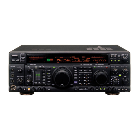
Yaesu FT-747GX User manual

t
OPERATING
MANUAT
FT-747GX
YAESU tllUSEN CO., LTD.
c.P.o. Box 1500
TOKYO, JAPAN

--T.
i
1. SPECIFICATIONS
TRANSMITTER
RECEIVER
GENERAL
ACCESSORIES
2. CONTROLS AND CONNECTORS
FRONT PANEL CONTROLS
REAR PANEL CONTROLS & CONNEC-
TORS
3. INSTALLATION
Preliminary Inspection
Base Station Installation
Equipment Location and Grounding
Antenna Considerations
Receiver Front End Protection
Mobile Power Connection
Mobile Mounting
Mobile Antenna Installation
Interconnections
Memory Backup
4. OPERATION
BASIC RECEPTION
Band Selection
Mode Selection
Tuning
SSB Reception
Attenuator (15); Noise Blank-
er (15); Squelch (15)
CW Reception
AM Reception
FM Reception
RTTY and Packer Receprion
TRANSMITTER OPERATION
SSB Transmission
Clarifier (18)
CW Transmission
FM Transmission
AM Transmission
RTTY, HF Packet &. SSTV Trans-
mission
MEMORY OPERATION
VFO A/B Selection
VFO/Memory Selection
Mgmory Storage
Memory Recall
Changing Memory Mode & Fre-
quency
Split Frequency Operation
SCANNING
Selective Memory Scanning
PRIORITY CHANNEL MONITORING
CONTENTS
2
2
2
3
3
4
4
7
I
9
I
l0
l0
t0
ll
l1
ll
t2
t2
l4
16
r6
16
l7
l7
l7
l8
l8
l9
l9
20
20
20
20
20
2l
2l
2I
22
22
t4
t4
t4
15
15
5. MODIFICATIONS & OPTIONS 23
Top Cover Removal 23
AGC Time Constant Selection 24
Tx Control for FC-757AT & FL-7000 24
Optional FM Unit Installation 24
Optional TCXO Installation 25
6. CAT SYSTEM COMPUTER CONTROL 26

FT-747GX
HF ALL MODE
COMPUTER AIDED TRANSCEIVER
The FT-747GX is a compact SSB/CWAM and (optionally) FM transceiver for rhe amareur radio
service, providing 100 watts of PEP transmitter power output on all hf amateur bands, and
general coverage reception from 100 kHz to 30 MHz.
Convenient features inciude operator selectable mode-dependent tuning steps, twenty memory
channels which store mode, simplex or split frequencies and scanning status, auto-resume scan-
ning of selectable memories, a clarifier, and a CAT (Computer Aided Transceiver) System for
user programming and more advanced control by an external computer. Wideband (0 kHz) AM
and narrowband (500 Hz) CW IF filters are included as standard. A switchable 20dB receiver
attenuator and noise blanker are provided to optimize reception under varying conditions.
The transmitter power amplifier is enclosed in its own diecast aluminum heatsink chamber
inside the transceiver, with forced-air cooling by an internal fan allowing full power FM and
AFSK operation when used with a heavy duty power supply. Optional accessories include your
choice of the MD- I 88 Desktop Scanning Microphone or the MH- I 88 Handy Scanning Micro-
phone, and the microprocessor controlled FC-757AT or FC- 1000 Automatic Antenna Tuners or
FL-7000 500-watt Automatic Solid State Linear Amplifier.
Special power supplies for the FT-747GX include the FP-757HD Heavy Duty Series-Regularor
Power Supply with forced-air cooling and automatic thermal fan control, or the FP-700 stan-
dard power supply for low power and light-duty applications. Both power suppiies can be wired
for 100/ll0/117/200/220 or 234 VAC.

TRANSMITTER
Frequency range
l60m band - 1.5 to 1.9999 MHz
80m band - 3.5 to 3.9999 MHz
40m band - 7.0 to 7.4999 MHz
30m band - 10.0 to 10.4999 MHz
20m band - 14.0 to 14.4999 MHz
l7m band - 18.0 to 18.4999 MHz
15m band - 21.0 to 21.4999 MHz
l2m band - 24.5 to 24.9999 MHz
10m band - 28.0 to 29.9999 MHz
Emission types
LSB, USB (J3E); Cw (AlA); AM
and optionally FM (F3E)
Power output
SSB, CW & FM*: l00W PEP/DC,
AM: 25W Carrier
SSB Carrier suppression
better than 40dB below peak output
Unwanted sideband suppression (SSg)
betrer than 50dB (l kHz tone)
Spurious radiation
Harmonic: better than -50dB
Non-Harmonic: better than -40d8
Audio response
Iess than -6dB from 400 to 2600H2
3rd order intermodulation distortion
better than -25d8 (@100W PEP)
Modulation systems
SSB/CW: active balanced modulator
AM: early stage (low level)
FM*: variable reactance
Maximum FM* deviation
x 2.5 kHz
I. SPECIFICATIONS
Microphone impedance
500 to 600 ohms
RECEIVER
Frequency range
100 kHz to 29.9999 MHz (continuous)
Circuit type
CW, SSB, AM: double conversion
FM*: triple conversion
Clarifier range
(A3E) t9.975 kHz
Sensitiviry, (for lOdB S+N/N, exc FM)
0.5-1.SMHz >1.5MHz
SSB/CW:
AM: 0.5uV 0.25uV
2uY l.0uV
FM*: 0.7uV for l2dB SINAD (above 21MHzl
Squelch sensitivity
SSB/CWAM:2.0uV above 1.5 MHz,
4.0uV within 0.5-1.5 MHz
FM*: 0.32uV
Intermediate frequencies
47.055MH2, 8.2 1 5MH z, 455kHz(FM-only*)
Image rejection
better than 70dB within 1.5-30MHz
IF rejection
better than 60dB within 1.5-30MHz
Selectivity (-6l-60d8)
SSB, CW(W), AM(N): 2.2/5 kHz
Cw(N): 500 Hz/r.8 kHz
AM(W): 6/14 kHz; FM(-6l-s0dB)*: 8/l9kHz
Maximum audio power output
at least l.5W into 8 ohms VlOolo THD
* FM operation requires optional unit.

Audio output impedance
4 to 8 ohms
GENERAL
Tuning steps (selectable)
SSB & CW: 25 Hz or 2.5 kHzlstep
AM: 100 Hz or I kHz/step
FM*: 12.5 kHz or 5 kHzlstep
Frequency stability (0o to +40'C)
SSB, CW, AM: x200 Hz
FM: t300 Hz
Frequency accuracy
SSB, CW, AM: t200 Hz
FM: t300 Hz
Antenna impedance (nominal)
50 ohms, unbalanced
Supply voltage
13.5 V DC tlOo/o (neg. ground)
Maximum current consumption
19A (@100W ourput)
Dimensions (WHD)
238 x 93 x 238mm (without knobs)
Weight (approx)
3.3 kg (7.25 lb)
S peci fications may be sub ject to change
without notice or obligation.
ACCESSORIES
Supplied
DC Power Cord (do fuse)
20A Fuses (2 supplied)
Options
Model
Part No.
T9014900
Q0000009
Part No.
MD-188 Desktop Scanning Mic. DI000039
MH-188 Hand Scanning Mic. D1000040
FRB-757 Relay Control Box D3000280
MMB-38 Mobile Bracket D6000032
External Computer Interfaces
FIF-65A for Apple II
FIF-232 for RS-232C
FP-757HD Heavy Duty Power Supply
FP-700 Standard Duty Power Supply
FC-757AT Automatic Antenna Tuner (100W)
FL-7000 500W Automatic Linear Amplifier
FAS- 1-4R Remote Antenna Selector (for
use wirh FC-757AT or FL-7000)
SP-767 Base Station Loudspeaker
SP-767P Base Loudspeaker dPhone Patch
SP-55 Mobile Loudspeaker

2. CONTROLS AND CONNECTORS
FRONT PANEL CONTROLS
@@(D @@@
t
@
(l) PowER
This pushbutton switch turns the transceiver
on and off. Frequency and mode data in the
memories and vfos is not affected by this
switch (or by whether power is connected to
the transceiver), since the data is retained
by an internal lithium battery.
(2) MlCrophone
MICROPHONE
UP
D\NN PTT
FAST
This 8-pin connector accepts the plug of the
MD- 188 Desktop Mic or MH- I 88 Hand Mic.
Scanning control lines from these micro-
phones allow pushbutton fast and slow tuning
and scanning from the microphone.
(3i PHONES
Mo naur a I or s tereo he ad ph o nes wi th 4- 1 6
ohms impedance may be connected to this
jack. Stereo headphones with a 3-conductor
plug reproduce audio in both ears, as with
monaurai headphones with a 2-conductor
plug. Inserting a plug into this jack disables
the internal or external loudspeaker.
(4) CLAR
Press this button while receiving to activate
clarifier operation. The tuning knob then
tunes the receiver without affecting the
transmit frequency. Press this button again
to turn off the clarifier.
(s) D LOCK
This button disables the tuning knob and
microphone tuning buttons to prevent acci-
dental frequency changes.'TLOCK'r is shown
on the display when active. Press this button
again to re-enable tuning.

(6) Tuning Knob and (7) FAST button
When operating on a vfo, this knob tunes at
a rate determined by the operating mode and
selected by the FAST button:
MODE FAST ON FAST OFF
(ll) Momentary Push Keys
< MODE >
Press either side of this see-saw button to
select rhe operating mode: LSB, USB, CW,
AM and FM. The mode is indicated on the
display above the operating frequency (in the
above order). Press the left side to select a
mode left of the present one displayed, or
the right side to select a mode ro the righr
(FM operation requires the optional FM Unit).
VFO >M
Press this button when operating on a vfo to
store the frequency and mode data from that
vfo into the memory (whose number is dis-
played at the right). This will overwrite
previous memory data, and leave the vfo and
memory the same. When operating on a mem-
ory wi th the squelch closed, this button
toggies the selective scan feature.
M >VFO
Press this button when operating on a mem-
ory to transfer its data into the last-used
vfo. This overwrites previous vfo data,
leaving the vfo and memory the same. After
pressing this button operation is on the vfo.
VFO/MR
This see-saw button switches operation
between the vfos and the memory. When
operating on a vfo, pressing the VFO side
selects the other vfo (a or B, displayed),
and pressing the MR side selects the memory
(number dispiayed)- When operating on a
memory, pressing the VFO side selects the
last-used vfo. The frequency and mode data
in the vfo and memory are unaffected- The
display indicates which (VFO A, VFO B or
MemoRy) is currently selected.
SPLIT
Press this button to activate split-frequency
operation between the two vfos, and press it
again to cancei split operation.
SSB/CW
AM
FM*
2.5 kHz
1 kHz
12.5 kHz
25 Hz
100 Hz
5 kHz
* requires optional FM Unit
When operating on memories, the tuning
knob selects the operating memory.
(8) BAND button
When receiving on a vfo, this bucton is used
to change frequency bands by providing 500
kHz tuning knob steps.
(e) AF/SQL
The inner AF control adjusts receiver volume.
The outer squelch control sets the threshoid
level of incoming signals or noise at which
receiver audio is muted. Clockwise rotation
increases the threshold level, causing the
receiver not to respond to background noise
or weaker signals.
(IO) MIC/DzuVE
The inner MlCrophone control adjusts the
gain of the transmit audio amplifier during
SSB and AM transmission (for FM, gain is
preset internally). This adjusts output power
in SS B modes, and modulation level in the
AM rnode. It is disabled for FM and CW.
The outer DRIVE control adjusts the carrier
power output level for CW, AM and FM
transmission. This control is disabied during
SSB transmission.
Pzu-M
This button activates priority monitoring of
the memory while operating on a vfo. This
feature is. described in the Operation section.
(l2l NAR (Narrow) Button
This button selects narrow IF filters when
operating in the CW or AM modes. "NARr is
displayed above the rightmost frequency digit
when a narrow filter is selected.
(13) ATT Button & Indicator Lamp
Places a 20dB attenuator in the receiver front
end circuit, to avoid overload of the rf amp-
lifier and mixer when listening to very strong
signals, by reducing the sensitivity of the
receiver. The indicator on the button glows
green when the attenuator is on.
(14) NB (Noise Blanker) Buuon
Activates the noise blanker for
AM reception.
(15) MOX Button
Manually switches the transmitter on and
off. This button MUST be in the OUT posi-
tion to receive.
(16) Display
All of the segments of the display are shown
in the diagram below. To the left of the
operating frequency, the display the indi-
cators signify as follows:
BAND -
SCAN -
BUSY -
LOCK -
SPLIT -
CLAR -
FAST -
VFO A-
VFO B-
MR
blinks when changing band
the operating memory is activated
for scanning. Blinks when scanning.
the squelch is open
tuning knob locked
split frequency operation active
clarifier active
fast (coarse) tuning active
operating vfo, or
or
operation is on the memory
SSB, CW and (17) ON AIR Indicator Lamp
The digital frequency display indicates the
operating frequency with 100 Hz resolution.
The number of the active (or last-used)
memory (00 thru 19) is displayed ro the
right of the frequency (with 'CHr above).
This lamp glows red when transmitting.
(18) Meter
The meter shows relative signal strength in
S-units on the uppermost scale when recei-
ving, and relative power output (PO), when
transmitting.
tE'sE, tEE tEE refl' Zfr' mt EEE' f,]t
E fl.E E E.fl {n
V^.
EEM EEIE WA
ftnlv EEII wEl

REAR PANEL CONTROLS & CONNECTORS
(l) CAR ADJ Potentiometers
These (recessed) trimmer capacitors set the
IF passband center offset from the carrier.
They are aligned at the factory and should
not be adjusted without proper test equip-
ment. The procedure is described in the ftFT-
747GX Technical Supplement".
(2) +13.5V
This phono jack provides 13.5V DC at up to
200 mA for powering accessories. The center
contact is positive.
Note: Repairs to damage caused by exceed-
ing the current capabilities of the accessory
DC jack may not be covered by the warranty.
@
(3) EXT SP (External Speaker)
This l/B-inch 2-conductor mini phone jack
provides amplified receiver output to drive
an external 4- to 16-ohm loudspeaker.
(4) KEY
This ]-inch 2-conductor phone jack accepts
a CW key or external electronic keyer" Open
circuit voltage is +l3V DC and closed circuit
current is 0.7 to I mA.
\*^ rulq\se\)

(5) AF OUT
This pho.no jack provides constant low-level
receiver audio, unaffected by the AF gain
control, for tape recording, digital demodula-
tors capable of high impedance input or an
external audio amplifier. Output level is
approximately 50mV peak at 10 kilohms.
@nductor
Shield braid
(6) EXT ALC
This phono jack accepts automatic level
control voltage for the transmitter from a
linear amplifier. The applied voltage should
be between 0 and -5V DC, referenced to the
outer contact (chassis ground).
(7) PTT Jack
This phono jack provides access to the PTT
line, for external receive/transmit switching.
Connecting the inner contact to the outer
contact (chassis ground) activates the trans-
mitter. Open circuit voltage is about 5V, and
closed circuit current is about I mA.
(8) BAND DATA
+t3v
TX GND
NC
A]
el
cf
oJ
LINEAR
DIN connector provides parallel
bandswitching signals for the
and FC- 1000 Antenna Tuners or
Linear Amplifier.
(s) DC l3.sv
This 4-pin connector accepts 12 to 15V DC
at 19 amperes (transmit), to power the trans-
ceiver.
CAUTION: AC voltage or DC outside of this
range may damage the transceiver.
(10) ANT Coaxial Jack
This type-M (SO-239) jack is for the antenna
system, antenna tuner or linear amplifier
input. Impedance requirement is 50 ohms,
unb a I anced. Use only a properly mating
type-M (PL-259) plug and 50- or 52-ohm
coaxial cable.
(11) GND
For best performance and safety, connect
this terminal to a good earth ground through
the shortest path possible.
(r2l cAr
O eNo
O Serial OUT
@ Serial lN
@ prr
@ AGc
@ t'lc
This 6-pin DIN jack provides access to the
serial data lines from the microcomputer and
A/D converter, for control of the transceiver
from an external computer. See the CAT
section of this manual for details.
O
@
@
@
@
@
o
@
This 8-pin
TT L- level
FC-757AT
rhe FL-7000

3. INSTALLATION
Preliminary Inspection
When you open the packing carton, inspect
the transceiver carefully for any signs of
damage. Check that all exposed controls and
switches move freely, and that the cabinet
has no dents or scratches. If you notice any
damage, document it completely and contact
the shipping company immediately. Save the
packing materials for possible future use.
Base Station Installation
The FT-747GX requires a power source of 12
to 15 volts DC, capable of up to 20 amperes
peak. For base station installations, Yaesu
offers several AC power supplies which may
be used wirh AC line voltages of 100, I10,
ll7, 200, 220 or 234 VAC. However, before
connecting any power supply to the trans-
ceiver or AC line, make sure that the supply
is properly wired for the local line voitage,
and that the correct fuse in installed.
The FP-757HD is a heavy duty series regula-
ted power supply capable of full power trans-
missions for up to 30 minutes at a time (50o/o
duty cycle is recommended for continuous
operation). Forced-air cooling is provided
over an extra Iarge internal heatsink. The
FP-757HD requires a 6-amp fuse for 100, 110
or 117 VAC, or a 3-amp fuse for 200, 220 or
234 VAC. Power transformer primary connec-
tions for the different line voltages are
shown at the right.
The FP-700 power series regulated supply
may be used for light duty operation (CW,
SSB or reduced power AM or FM). AC volt-
ages, fuse requirements and power transfor-
mer wiring are the same as for the FP-757HD
described above and shown in the diagram
below, but the plastic sleeve on the supply
DC cable must be cut to allow connection to
the speaker in the power supply.
NEVER CONNECT AC, OR DC ABOVE
l5v, DIRECTLY TO THE FT-747GX.
Make certain that the POWER switch on the
front panel of the FT-747GX is OFF (out)
before connecting power to the transceiver,
and double check ro make sure that the pol-
arity of the connections is correct before
switching the transceiver on.
Power Transformer Primary Connections
NOTICE
THE FOLLOWING ABUSES MAY CAUSE
DAMAGE TO THE EQUIPMENT WHICH IS
NOT COVERED UNDER WARRANTY:
CONNECTION OF AC VOLTAGE OR
IMPROPER DC VOLTAGE DIRECTLY TO
THE TRANSCEIVER.
(2) INCORRECT (REVERSED) POLARITY
POWER CONNECTION.
USE OF AN IMPROPER FUSE IN THE
POWER SUPPLY.
AC
ltov AC
toov
I
ir
I
tr
AC
220V
lI
Ilr
.ffu
FP-757HD

Equipment Location and Grounding
In all base station installations, the GND
terminal on the rear panel of the transceiver
should be connected by a heavy braided
cable to a good earth ground. Best perfor-
mance on all frequencies may require that
the grounding cable be less than l0 feet (S
meters) long. All station equipment should
have its own grounding cable (independent of
signal or control cables), connected to a
common point on the ground bus close to the
transceiver or linear amplifier (if used). See
the diagram below.
Locate the transceiver so that air can flow
freely into the air intake on the left side,
and out the rear. Avoid placing the trans-
ceiver on top of another heat generating
device such as a linear amPlifier.
Antenna Considerations
The FT-747GX is designed for use with any
antenna system having a 50-ohm resistive
impedance at the operating frequency. Auto-
matic final protection (AFP) circuitry is
included to protect the final transistors by
automatically reducing power output when an
impedance mismatch (hiSh SwR) is present.
With an SWR of 3:l for example, about 75olo
of full power output is available.
Despite this protection, the transmitter should
never be activated unless an antenna or
dummy load is connected to the ANT jack.
Use 50-ohm coaxial cable with a proper
@eo o
@(
C= @rEt"€l
(type-M, PL-259) plug to connect the trans-
ceiver to the antenna or load, and if SWR is
too high to permit the desired performance,
connect an antenna tuner such as the auto-
matic FC-757AT or FC- 1000 between the
transceiver and the antenna. See page 12 for
interconnection information.
Receiver Front End Protection
The receiver front end in FT-747GX includes
a surge suppressor and a lamp fuse to protect
the sensitive receiver circuitry from high
voltage pulses (EMP) at the antenna terminal,
and a choke to bypass DC overload. Several
thousands of volts can develop naturally
when dry wind or electrical storms create an
electrostatic charge on the antenna elements,
and this ib delivered to the antenna jack if
the antenna is connected to the transceiver-
In such a case, the lamp fuse may burn out
(even if the transceiver is turned off at the
time). The only sure way to avoid this condi-
tion is to disconnect the antenna from the
transceiver whenever the weather is likely to
create high voltage on the antenna (the
feedline should be grounded to allow the
charge to dissipate).
If the receiver is found to have suddenly
lost sensitivity, inspect the filament of the
lamp fuse (Fl00l on the MAIN Unit). If it is
open, determine the cause of the overvoltage;
eB., was the antenna left connected during
an electrical storm or dry windy weather
since you last used the equipment? To obtain
replacement lamp fuses, ask your local Yaesu
ooooooO
Station Ground Connections

dealer for Yaesu part no. Q1000010, BQ04l-
22803A; or substiture any 8V 100mA pilot
lamp. Do not jumper across the lamp fuse
terminals however, as this will defeat the
protection and eould result in serious damage.
Mobile Power Connection
(Negative Ground vehicles only)
The DC power cable for mobile installarion
is supplied with the transceiver. Please review
the NOTICE on page 9 before connecting
power. The DC cable should be connected
directly to the vehicle battery, rather than
to the ignition or accessory circuitry. Route
the cable as far away from ignition cables as
possible, and then cut off any extra cable in
order to minimize voltage drop losses.
(l) Do not connect the cable to the transcei-
ver until after the proper connections
are made to rhe bartery; rhe RED cable
lead to the POSITIVE battery terminal,
and BLACK lead ro the NEGATIVE rerm-
inal. Make sure the battery terminal
connections are tight, and remember to
check them periodically for signs of
loosening or corrosion.
Measure the voltage across the battery
terminals with the engine running fast
enough to show a charge. If above l5
volts, the automobile voltage regulator
must be adjusted to reduce the charging
voltage before proceeding.
Make sure the POWER switch on the
transceiver is OFF, and connect the DC
cable to the transceiver. The plug pin
connections are shown on page 8.
The positive RED wire musr include a 20
amp fuse, installed in the supplied cable.
Always check to ensure the POWER switch is
OFF before starting the engine.
Mobile Mounting
The optional MMB-38 Mobile Mounring Brac-
ket for the FT-747GX allows quick insertion
and removal of the transceiver from the
vehicle. Complete instructions are provided
with the bracket, which may be installed
either above or underneath the transceiver
as shown here.
Mobile Installations
Mobile Antenna Installation
Please review the base station antenna infor-
mation on the previous page. An antenna
tuner such as the FC-757AT or FC- 1000 is
particularly desirable in a mobile station,
where the short antenna elements have very
narrow bandwidth. Make sure rhat the shield
of the antenna coax is firmly grounded to
the car body at the antenna feedpoint.
A
\-/ BATTERv
@ TERMTNALS
20A for FT-747GX,
6,4' for FT-747SX
(2)
(3)
FUSE HOLDER DC FUSE Ratings:

Interconnections
Linear Amplifiers
The FT-747GX includes a high voltage (150V)
transistor switch capable of handling up to
1.5 amperes DC, to control transmiy'receive
switching of a linear amplifier via pin 6 of
the BAND DATA jack. However, make certain
that the t/r switching requirements of your
linear amplifier do not exceed these limits,
and that the linear switching voltage is +DC,
and not -DC or AC. Yaesu offers the optional
FRB-757 Relay Box for r/r switching of lin-
ears that require negative or AC switching,
or higher voltage or current switching. The
FRB-757 installs between the relay jack on
the amplifier and the PTT jack on the trans-
ceiver, and is capable of switching up to
250V AC or DC, at up to 2.5A.
If you are installing the FT-747GX with the
FL-7000 Auto-Tune Linear Amplifier or the
FC-757AT Automatic Antenna Tuner, set
internal switch S02 to position I as described
on page 25.
FC-1000 Controller Unit
Memory Backup
The memories and vfos of the FT-747GX are
retained by an internal lithium cell for five
years or longer. The backup circuit is turned
on at the factory, so it is not necessary to
do anything unless the battery runs down, in
which case memories will be lost when the
transceiver is turned off and power removed.
If this occurs, contact your Yaesu dealer for
replacement of the lithium battery.
If you want to clear all memories, or if you
plan to store the transceiver for a long time
without power connected, disable the backup
system by moving the backup switch (inai-
cated on page 22) to its alternate position. If
clearing memories, do this with the power
disconnected, wait 30 seconds, and then set
the switch back ON before restoring power.
INTERCONNECTION DIAGRAMS
FC-1000 Tuner
oO O
(T910t367)
AESI'
{3
=3
o=
oF
r
e
c! -t
rO ca
@o
oo
oo o
o)
FO
FT-747GX
e
(T910r370A)

AT{T B-2
E-l
B -/t
l-3
{Hfr==
{H'b=
{MF3
{Hb
-ACC -
t2
bol
(T9t001604)
ms-l-4R
|NPUT ( I 2
oooooo
"ff@6".3rI,,
(D400001 9)
F\
co
co
o
o)
F(r9100980)
FL-7000
o a--) (
r\\-=Jn
il t)
Y^1"
o(
oeCoorO
FT-747GX

4. OPERATION
BASIC RECEPTION
Before plugging the power supply into the
wall outlet (in base installation), ensure that
the power supply is wired for your AC line
voltage. Make certain that the proper fuse is
installed, and that the supply is properly
connected to the transceiver as described in
the Installation section. Also make sure the
antenna and grounrl are connected.
Connect a microphone, if desired, to the
MIC jack. For CW operation, connect a CW
key (or external keyer) as shown on page 7
to the KEY jack on the rear Panel.
Preset the POWER switch off, and all push-
buttons to the undepressed position. Set the
knobs all fully counterclockwise.
Confirm that the MOX button is OFF (unde-
pressed (out) position), and then switch on
the power supply, followed by the transceiver
POWER switch. The meter and display will
light, with the display indicating the default
(memory clear) state: VFO A, LSB, 7.000.0.
Band Selection
Press the BAND button and immediately turn
the tuning knob (or press the microphone
DWN/UP keys) to tune in 500 kHz steps
(tr BAND'r appears blinking on the display).
Press the BAND button a second time (while
'r BANDTT is still blinking) to set the new
displayed frequency in the vfo.
Pressing the BAND button the first time
starts a S-second timer, which is reset when-
ever the tuning knob is moved (or mic key
pressed). However, if you do nothing for five
seconds, " BANDtt will disappear and the
display will return to its original frequency.
Try this now: select the operating band for
which your antenna is resonant. Remember
to press the BAND button again when you
have the band selected (or yourll have to
start over).
-ii6: =+ ""1F8'
'/rr,r..' l*- .s" --l F-
The 500 kHz BAND steps can be used only
when tuning a vfo. You can use them to sel-
ect any 500 kHz range for reception, but
rransmission is limited to the 500 kHz seg-
ments containing amateur bands.
When selecting the operating band, you can
loop around from the low edge to the high
edge of the transceiver frequency range and
vice-versa, but this automatically resets the
operating frequency to the nearest 500 kHz
step. For example, if you tune to I10.5 kHz
and then press the BAND button and tune
(one step) lower (tuning knob counterclock-
wise one click), the display will change to
29.500.0. Then, if you turn the knob back
one step, the display will show 500.0. If you
do not tune through the frequency limits
(100 kHz and 30 MHz) during band changing,
the digits under 500 kHz are preserved.
Mode Selection
From the LS B mode, just press the right
side of the MODE button (repeatedly, if
necessary) to select the desired operating
mode. From other modes, you may need to
press the other side of the MODE button
until the mode you want is displayed.
Because the tuning steps are larger in AM
and FM modes than in CW and SSB, least
significant frequency digits are zeroed when
6;;a
*ll
<5s --l

switching from CW, SSB or AM to FM (5 kHz
steps). 25 Hz fine steps are still available in all
modes with the ClARif,rer, described later.
Turn the AF gain control clockwise for com-
fortable receiver volume.
Tuning
Press the FAST button on the front panel
(or microphone) to select course tuning steps
(rrFASTil is displayed). Press it again to return
to fine tuning. Notice that coarse and fine
tuning steps are mode-dependent, as shown
on page 5. In CW and SSB modes the fine
steps are 25 Hz, so only every fourth step
will change the displayed frequency.
The FAST button on the microphone greatly
facilitates vfo tuning with the tuning knob:
operate the tuning knob with one hand while
operating the FAST button on the mic with
your other hand. This allows quick searching
for activiry (with rhe FAS T funcrion on),
and then easy fine tuning when rhe FAST
function is turned of f. Of course you can
also tune up or down using the UP or DWN
keys on the microphone.
NOTE: The tuning knob and microphone keys
are deactivated when rhe D LOCK (dial lock)
function is active. When the dial is locked,
TLOCKT appears on the display. Press the D
LOCK button to toggle the lock on and off.
SSB Reception
The ATT and NB switches and rhe SQL con-
trol are provided to reduce or eliminate the
various types of noise and interference that
can obstruct comfortable reception. Oper-
ation is first described for SS B (USB or
LS B) reception on an amateur band, with
variations for other modes described later.
Press the MODE button to select USB and
tune to the 14, 2l or 28 MHz phone band
(or, if your antenna is for a band below l0
MHz, select that band and the LSB mode).
Attenuator
On a clear frequency, check for any S-meter
reading on the background noise level (hiss
or crackle). If the S-meter deflects above 3,.
turn on the attenuator (press ATT: its indi-
cator will glow green). This improves receiver
performance in the presence of strong signals
or high noise levels.
The attenuator may often be needed on fre-
quencies below l0 MHz, particularly if you
are using a large antenna or your station is
in a noisy environment (city).
Noise Blanker
Pulse-type noise, either short duration types
such as from ignition systems and electric
motors and switches, or long duration over-
the-horizon radar (ttwoodpeckertt) signals, can
be reduced or removed by pressing the NB
button. However, when noise blanking is not
required the NB button should be off (out),
to minimize distortion introduced by the
blanking process.
Squelch (All Mode)
When waiting for a scheduled call on a fairly
uncrowded band the squelch can be activated
to silence the receiver until the call. Just
tune to the scheduled frequency and turn the
SQL control clockwise until the receiver is
quiet. Two other things happen when the
squelch is closed: the S-meter reading drops
to zero (if it wasnrt already), and rrBUSYrl
disappears from the display.

Of course using the squelch to wait for a
signal to appear only rvorks if the expectetl
signal is strong enough to overcome the
squelch threshold set by the SQL control' If
the ex pected signal will be weak, or when
operating in modes other than FM and not
scanning, the SQL control should be set fully
counterciockwise.
Note: Whenever using the squelch feature,
make sure to set the ATTenuator switch as
described previously before adjusting the
SQL cr)ntrol, as the squelch threshold is
affected by the ATT setring.
CW Reception
In addition to the ATT, NB and SQL controls
described for SSB, the FT-747GX CW NAR
(narrow) mode provides a 500 Hz IF crystal
filter to enhance reception. Use the CW
(wide) mode to tune in the desired signal for
about a 700 Hz pitch, and then press the
NAR switch.
The CW (wide) mode provides the same IF
bandwidth as for SSB, allowing you to hear
signais up to about 1 kHz away while tuning
around the band. Noise and interference are
greater than for CW NAR, but the wider
bandwidth makes tuning easier.
Hint: when you make contact with another
station on CW, press the CLAR button after
he responds to you if you need to retune'
then press the D LOCK button to avoid acci-
dental frequency change, and finally the
NAR button to select the narrow filter.
AM Reception
The FT-747GX includes a 6 kHz (wide AM)
filter for good fidelity during reception of
mediumwave and shortwave AM broadcasts.
Pressing the NAR switch reduces the band-
width to the same as SSB, but fidelity is
reduced.
When interference or noise is severe' ECSS
(Exalted Carrier Selectable Sideband) recep-
tion may be preferable over the AIvl mode
for receiving AM signals. This special tech-
nique ailows you to select either the upper
or lower sideband of an AM signal using
US B or LSB modes; eliminating interference
that may be present on the other sideband
due to a nearby signal while still getting
about twice the audio bandwidth (fidelity) of
the AM narrow mode.
To use ECSS, first tune in the station using
the AM mode (shortwave broadcasters gen-
erally transmit on precise multiples of 5
kHz), and then select either USB or LSB,
whichever gives best reception. Now carefully
fine tune for zero beat (most natural voice/-
music pitch), and push D LOCK so you don't
loose the frequency.
Hint: Zero beating an AM signal in ECSS
reception requires very precise setting of the
tuning knob. Some practice with stronger
signals first will make tuning the weak ones
easier. Coarse tuning is useless for ECSS.
When receiving AM signals in either AM or
ECSS mode, the noise blanker should be off
unless it is really needed. Its effectiveness
will vary depending on the signal strength of
the received signal and those on adjacent
channels; being most ef fective when the sig-
nals are weak and noise pulses are strong.
FM Reception
The FT-747GX requires the optional FM Unit
(circuit board) for FM oPeration.
The MIC gain controi and noise blanker (NB)
switch are disabled for FM operation- How-
ever, the ATT and SQL settings are especially
important. For weak signai work, set the

SQL control only after you have finished
tuning. The FT-747GX FM Unit is designed
for t !.5 kHz deviation, as is most common in
2-way FM communications.
RTTY and Packet Reception
An ex ternal TU (terminal unit) or TNC
(terminal node controller) is required for
RTTY or packet operation, respectively.
Receiver audio is best obtained from the AF
OUT jack on the rear panel, as the level of
the signal at this jack is not affected by the
AF gain control. However, your TU or TNC
must be capable of high impedance input
(50mVp-p @10 kilohms) to use this signal.
Otherwise, low impedance oucput is available
from the EXT SP jack, but this is affected
by the AF gain control, and using this jack
disables the internai speaker. Select either
the LSB or USB mode for operation, and see
your TU or TNC manual for further details.
TRANSMITTER OPERATION
The solid state transmitter in the FT-747GXt
requires no adjustment other than setting the
desired output level. The maximum power
output is determined by the mode and the
capability of the power supply (in AM, FM
and RTTY, power should be restricted to
avoid overheating the power supply if you
plan to make long transmissions). Also, there
are certain precautions to be observed at all
times when transmitting to avoid possible
damage to the transceiver, and to assure a
clean signal.
Never transmit without having a dummy load
or antenna tuned to the operating frequency
connected to the transceiver (or linear ampli-
fier, if used). If you have doubts about the
suitability of your antenna on a certain
frequency, check the SWR (Standing Wave
Ratio) first using an external SWR meter.
The transmitter includes protection circuits
that reduce the outpuc power if SWR is high.
For example, with an SWR of 3:1 only about
75o/o of full power is available, but very high
SWRs can cause poor performance due to
feedline radiation and RF feedback in the
shack. If using the FC-757AT Automaric
Anienna Tuner or FL-7000 Linear Amplifier,
SWR is calculated and dispiayed automatically.
See the Tuner or Amplifier manual for com-
plete details. Otherwise, use an external SWR
meter such as the Yaesu YS-60, connected
between the transceiver and antenna feedline.
Avoid changing frequr:ncy during transmission.
First return to receive, then do your tuning,
and remember to listen for at least a minute
or two to make sure the new frequency is
not aiready occrrpied; or ask if the frequency
is occupied and then listen for a response.
When using a light- or medium duty power
supply such as the FP-700, do not attempt
to transmit FM, AM or RTTY ar full output
power. Although the transceiver is capable
of this, some power supplies are not, and
they may rapidly overheat and be seriously
damaged. In any mode, feel the supply occas-
ionally and reduce power or stop transmitting
for a while if it feels hot.
Never start transmitting (except into a dummy
load) without first listening for a few min-
utes to make sure the frequency is clear,
and then transmit your callsign. This prevents
accidental interference to other stations.
SSB Transmission
With a microphone connected to the MIC jack
on the front panel, preset the MIC gain
control to 12 orclock, tune to a valid trans-
mitting frequency (in the amateur bands), and
select the LS B mode (on bands below l0
MHz) or the USB mode.
To activate the transmitter, close the PTT
switch on the microphone, and adjust the

MIC gain conlrol while speaking into the
microphone so that the meter deflects up to
about 6 on the PO scale on voice peaks.
This will result in full power output; reduce
the MIC gain to reciuce Power.
Clarifier (Receiver Offset)
The CLAR button can be pressed while recei-
vi ng to allow independent tuning of the
receiver (in 25 Hz steps) without affecting
the transmit frequency (CLAR is displayed to
the lef t o f the operating frequency). This
feature is useful if, after making contact
with another station, his transmitter drifts;
you can retune his signal without changing
your own transmitting frequency.
While the clarifier is on tuning affects only
the receiver: the lransmitting frequency
remains the same as before the clarifier was
activated, and is displayed when transmitting.
The FT-747GX incorporates a special'clari-
fier memory', which allows you to listen on
the transmit frequency by switching off the
clarifier. As long as you donrt touch the
tuning knob, pressing CLAR again returns
you to the same (offset) receive frequency.
When the contact is finished, remember to
switch off the clarifier.
CW Transmission
The FT-747GX offers semi break-in operation
for both simplex and split-frequency opera-
tion. Connect your key or external electronic
keyer to the KEY jack on the rear panel,
and select the CW mode. Close the key to
activate the transmitter, and adjust the
DRIVE control for the power output desired
(100W output - rrSrr on the PO meter scale).
Af ter making contact with another station,
reduce power with the D RI V E controi as
much as possible without loosing contact.
You should be able to hear the sidetone from
the loudspeaker (or headphones) when you
close the key. The sidetone volume controi
(inside the hole near the rear of the bottom
cover) can be adjusted for comfortable side-
tone volume.
To practice sending CW, just ser the DRIVE
control fully counlerclockwise. Now, closing
the key will generate the sidetone buc no
signal will be transmitted.
If you need to change the delay time belween
reiease of your key and receiver reactivation,
adjust VR1013 inside the top cover at the
location shown below.
FM Transmission (requires optional Unit)
For FM transmission, just seiect the FM mode
and close the PTT switch to transmit. The
MIC gain control is disabled or FM, as the
gain of the microphone amplifier is preset
internally for t 2.5 kHz d,>viation, and requires
no further adjustment. RF.power output is
adjusted by the DRIVE control. For full
power output (using the FP-757HD power
supply), adjust the DRIVE so that the meter
deflects to u8" on the PO scale. When contact
is established, reduce the DRIVE.
Other manuals for FT-747GX
4
Table of contents
Other Yaesu Transceiver manuals

Yaesu
Yaesu FTM-400DR User manual

Yaesu
Yaesu 600 User manual

Yaesu
Yaesu FTM-10R User manual

Yaesu
Yaesu FT-230R User manual

Yaesu
Yaesu FTM-200DR User manual

Yaesu
Yaesu FTM-350R - SOFTWARE UPDATE PROCEDURE 7110 Manual

Yaesu
Yaesu FT-891 Manual

Yaesu
Yaesu FT-1000 Installation guide

Yaesu
Yaesu FT-5100 Manual

Yaesu
Yaesu FT-101E User manual

Yaesu
Yaesu FT-207R User manual

Yaesu
Yaesu FT-920 User manual

Yaesu
Yaesu FT-8800 Service manual

Yaesu
Yaesu FT-747GX Manual

Yaesu
Yaesu FT-817ND User manual

Yaesu
Yaesu FTM-400XDR User manual

Yaesu
Yaesu FT-857D User manual

Yaesu
Yaesu FT2DR User manual

Yaesu
Yaesu FT-7900R User manual

Yaesu
Yaesu FT-2000D User manual