Yaesu VX-8GR/GE User manual

144/430 MHz
DUAL BAND FM TRANSCEIVER
WITH GPS
OPERATING MANUAL
VX-8GR/GE
VERTEX STANDARD CO., LTD.
4-8-8 Nakameguro, Meguro-Ku, Tokyo 153-8644, Japan
VERTEX STANDARD U.S.A. Inc.
6125 Phyllis Drive, Cypress, California 90630, U.S.A.
YAESU UK LTD.
Unit 12, Sun Valley Business Park, Winnall Close
Winchester, Hampshire, SO23 0LB, U.K.
VERTEX STANDARD HK LTD.
Unit 1306-1308, 13F., Millennium City 2, 378 Kwun Tong Road,
Kwun Tong, Kowloon, Hong Kong
VERTEX STANDARD (AUSTRALIA)PTY., LTD.
Tally Ho Business Park, 10 Wesley Court, East Burwood, VIC, 3151

Contents
Scanning ..................................................................................... 54
General ................................................................................... 54
VFO Scanning ........................................................................ 56
How to Skip (Omit) a Frequency during VFO Scan ........ 57
Memory Scanning .................................................................. 58
How to Skip (Omit) a Channel during Memory Scan ...... 59
Preferential Memory Scan ................................................ 59
Memory Bank Scan .......................................................... 61
Programmable (Band Limit) Memory Scan (PMS) ............... 62
“Priority Channel” Scanning (Dual Watch) ........................... 63
Priority Revert Mode ....................................................... 64
Automatic Lamp Illumination on Scan Stop .......................... 65
Band Edge Beeper ................................................................. 65
GPS Operation .......................................................................... 66
Setting the Time Zone (Time Offset) ..................................... 67
Selecting the Display Units of the GPS Screen ...................... 68
Selecting the Map Datum ...................................................... 68
APRS®Operation ...................................................................... 70
Preparations ........................................................................... 70
Receiving an APRS Beacon ................................................... 73
Transmit an APRS Beacon .................................................... 76
Receiving an APRS Message ................................................. 79
Transmit an APRS Message .................................................. 81
ARTSTM (Automatic Range Transponder System) ................ 83
Basic ARTSTM Setup and Operation ..................................... 84
ARTSTM Polling Time Options .............................................. 84
ARTSTM Alert Beep Options ................................................. 85
CW Identifier Setup ............................................................... 86
Spectrum Analyzer Operation ................................................. 87
Smart Search Operation ........................................................... 88
Message Feature ........................................................................ 90
General ................................................................................... 90
Programming a Message ........................................................ 90
Programming a Member List ................................................. 91
Set your Personal ID .............................................................. 92
Sending a Message ................................................................. 93
Receiving a Message .............................................................. 94
Emergency Feature ................................................................... 95
Emergency Channel Operation .............................................. 95
Emergency Automatic ID (EAI) feature ................................ 96
Selecting the EAI mode and its Transmit Time ................ 97
Activating the EAI feature ............................................... 97
To Locate an Unresponsive Operator
using the EAI feature ............ 98
Internet Connection Feature .................................................... 99
General ................................................................................... 99
SRG (“Sister Radio Group”) Mode ....................................... 99
FRG (“Friendly Radio Group”) Mode ................................. 100
DTMF Operation ..................................................................... 102
CW Learning Feature ............................................................. 104
CW Training Feature .............................................................. 106
Sensor Mode ............................................................................. 107
Clock Set ............................................................................. 107
Miscellaneous Setting .............................................................. 108
Password .............................................................................. 108
Programming the dKey .................................................. 110
ATT (Front End Attenuator) ............................................... 111
Receive Battery Saver Setup ............................................... 112
TX Battery Saver ................................................................. 112
Disabling the BUSY Indicator ............................................. 113
Automatic Power-Off (APO Feature) .................................. 113
Transmitter Time-Out Timer (TOT) .................................... 114
ON/OFF Preset Timer .......................................................... 115
Busy Channel Lock-Out (BCLO) ........................................ 116
Changing the TX Deviation Level ....................................... 116
Changing the Microphone Gain ........................................... 117
S-and TX Power Meter Symbols ......................................... 117
Display Contrast .................................................................. 118
Display Dimmer ................................................................... 118
My Bands Operation ............................................................ 119
Changing the Status of the gKey .................................... 120
Reset Procedures ..................................................................... 121
Cloning ..................................................................................... 122
Set Mode ................................................................................... 124
APRS/GPS Set Mode .............................................................. 148
Specifications ........................................................................... 160
Appendix (Computer Connections) ....................................... 162
FCC Notice ............................................................................... 164
Introduction ................................................................................. 1
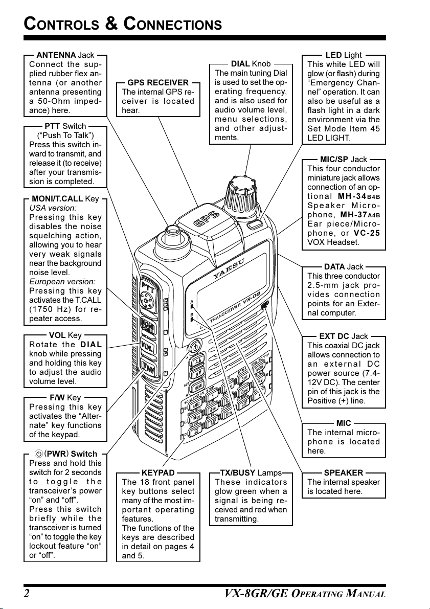
Controls &Connections ............................................................... 2
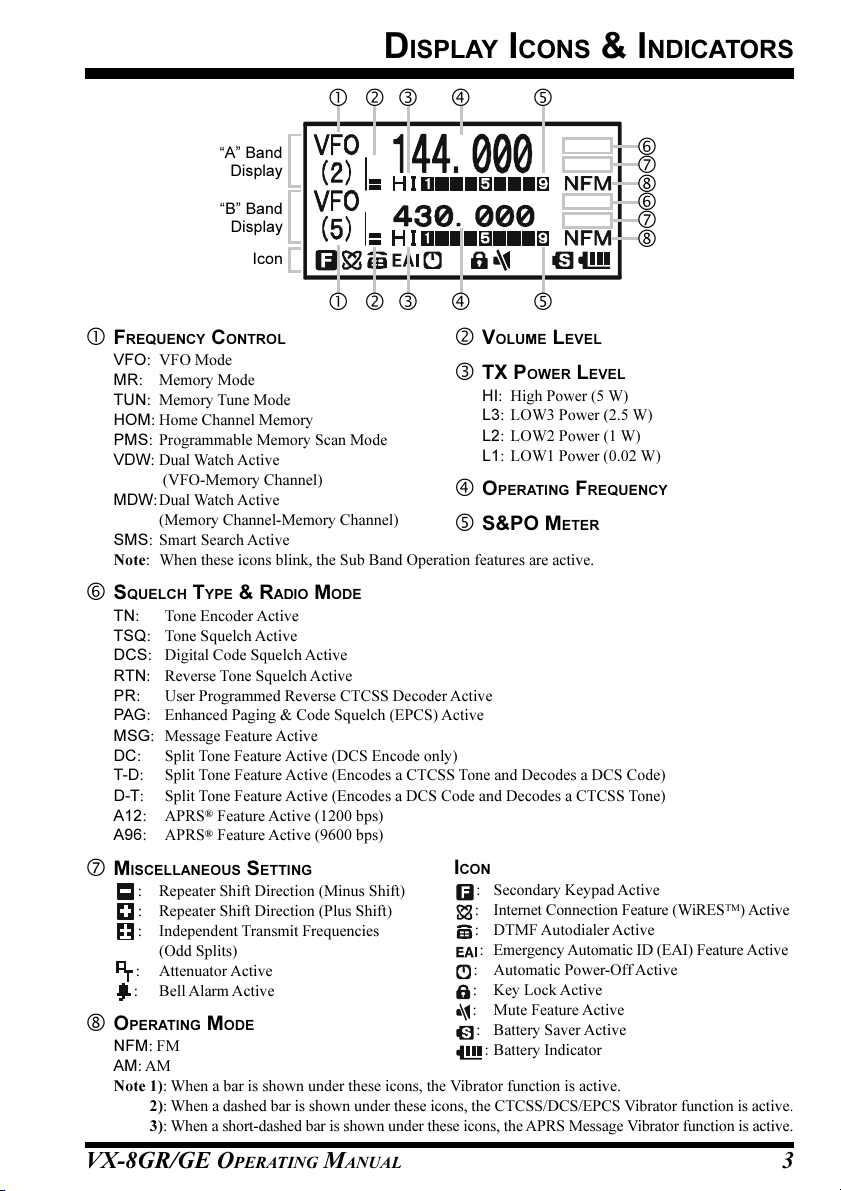
Display Icons & Indicators ......................................................... 3
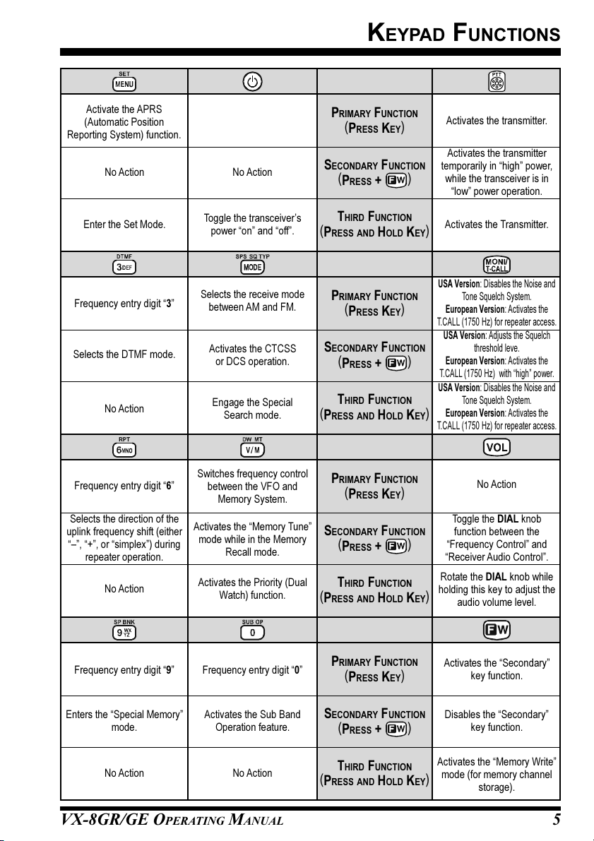
Keypad Functions ....................................................................... 4
Accessories & Option .................................................................. 6
Accessories Supplied with the VX-8GR .................................. 6
Available Options for your VX-8GR ....................................... 7
Installation of Accessories ........................................................... 8
Antenna Installation ................................................................. 8
Belt Clip Installation ................................................................ 8
Installation of FNB-101LI Battery Pack .................................. 9
Battery Life Information ........................................................ 10
Installation of FBA-39 Alkaline Battery Case ....................... 11
Interface of Packet TNCs .......................................................... 12
Operation ................................................................................... 13
Switching Power On and Off ................................................. 13
Adjusting the Volume Level .................................................. 13
Squelch Adjustment ............................................................... 14
Selecting the Operating Band ................................................ 15
Selecting the Frequency Band ................................................ 16
Frequency Navigation ............................................................ 17
Sub Band Operation ......................................................... 17
1) Tuning Dial .................................................................. 17
2) Direct Keypad Frequency Entry .................................. 17
3) Scanning ....................................................................... 18
Transmission .......................................................................... 19
Changing the Transmitter Power Level ............................ 19
Advanced Operation ................................................................. 21
Keyboard Locking ................................................................. 21
Adjusting the Keypad Beeper Volume Level ......................... 22
Setting the Frequency Display Image Size ............................. 22
Audio Muting ......................................................................... 23
Keypad/LCD Illumination ...................................................... 23
Changing the Channel Steps .................................................. 24
Changing the Receiving Mode ............................................... 24
SQL S-meter .......................................................................... 25
Repeater Operation ................................................................... 26
General ................................................................................... 26
Repeater Shifts ....................................................................... 26
Automatic Repeater Shift (ARS) ........................................... 26
Manual Repeater Shift Activation .......................................... 27
Changing the Default Repeater Shifts .............................. 27
Tone Calling (1750 Hz) ......................................................... 28
Checking the Repeater Uplink (Input) Frequency ................. 28
CTCSS/DCS/EPCS Operation ................................................. 29
CTCSS Operation .................................................................. 29
DCS Operation ...................................................................... 30
DCS Code Inversion ........................................................ 32
Tone Search Scanning ........................................................... 34
EPCS (Enhanced Paging & Code Squelch) ........................... 35
Storing the CTCSS Tone Pairs for EPCS Operation ....... 35
Activating the Enhanced Paging & Code Squelch System .. 36
Paging Answer Back ........................................................ 36
CTCSS/DCS/EPCS Bell Operation ....................................... 37
Programming the User Melody ........................................ 38
Split Tone Operation .............................................................. 39
CTCSS/DCS/EPCS Vibrator Operation ................................ 40
Memory Mode (Regular Memory Channel Operation) ......... 42
Memory Storage .................................................................... 43
Storing Independent Transmit Frequency (“Odd Splits”) ... 44
Memory Recall ....................................................................... 44
HOME Channel Memory ....................................................... 45
Labeling Memories ................................................................ 46
Memory Offset Tuning .......................................................... 47
Masking Memories ................................................................ 48
Memory Bank Operation ....................................................... 49
Assigning Memories to a Memory Bank .......................... 49
Memory Bank Recall ........................................................ 49
Removing Memories from a Memory Bank ..................... 50
Changing a Memory Bank’s Name .................................. 50
Moving Memory Data to the VFO ........................................ 51
Memory Only Mode ............................................................... 51
Memory Mode (Special Memory Channel Operation) .......... 52
Weather Broadcast Channels ................................................. 52
VHF Marine Memory Channels ............................................. 53

VX-8GR/GE OPERATING MANUAL 1
The Ultra Compact VX-8GR/GE (2.4”W x 3.7”H x 1.1”D) is equipped with a GPS receiver and
thinner than the previous advanced model - It is packed with advanced technology and fea-
tures, designed for outdoor operation. It is submersible (IPX5) and shockproof! The compact
case combines a rugged die-cast chassis with the clean, tough polycarbonate resin front panel.
Its shockproof versatility will allow you to operate the radio in the toughest environments.
The large High-resolution Dot Matrix LCD display provides clear, easy-to-read indication of
both “A” (Main band) and “B” (Sub band) frequencies, the operating mode, and S-meters for
both bands. When you engage the Spectrum Scope function, the high-resolution display will
indicate relative signal strengths of up to ±50 adjacent channels!
The built-in worldwide standard AX.25 Data TNC Modem permits uncomplicated APRS®
operation. (Automatic Packet/Position Reporting System: APRS®is a registered trademark of
the APRS Software and Bob Bruninga, WB4APR.) The VX-8GR/GE supports APRS®1200/
9600 bps data communication on the “B” (Sub band) band only. You may communicate your
location to other APRS®stations along with the position, speed and heading displayed on your
radio! You and others will be able to see your APRS®movement on the web! The VX-8GR/
GE displays the received station’s positions, heading directions, messages, distances, icons (43
kinds), weather information, object, etc. With the list function you may automatically store and
recall up to 30 messages and the APRS®data from up to 50 stations. The built-in GPS Receiver
Unit provides you with real time APRS®data.
Enhanced Paging and Code Squelch (EPCS) allow you to page a particular station and only
receive calls from that station. A security Password may be set, which will allow you to turn on
and operate the transceiver only after you enter the Password. A convenient key provides ac-
cess to Vertex Standard’s WIRES™(Wide-Coverage Internet Repeater Enhancement System).
The Emergency Automatic ID (EAI) function can automatically cause your VX-8GR/GE to
transmit your callsign and engage your rig’s microphone, even if you are disabled and unable
to press the PTT switch. Additional features include: transmit Time-Out Timer (TOT), Auto-
matic Power-Off (APO), and Automatic Repeater Shift (ARS). Yaesu’s exclusive ARTS™
(Auto-Range Transponder System) which “beeps” the user when you move out of communica-
tions range with another ARTS™equipped station. There is provision to reduce the TX devia-
tion for use in areas of high channel congestion. The squelch circuit allows adjusting the squelch
to open at a programmable setting of the S-Meter, thus reducing guesswork in setting the
squelch threshold. Provides a DATA jack which enables the display of location data (Lat/Lon)
from an after-market GPS receiver, and outputs the location data (Lat/Lon) of the built-in GPS
receiver unit and the Waypoint data of the received APRS beacons.
We appreciate your purchase of the VX-8GR/GE, and encourage you to read this manual
thoroughly, and learn about the many exciting features of your thrilling new Yaesu hand-held
transceiver!
INTRODUCTION

VX-8GR/GE OPERATING MANUAL2
CONTROLS & CONNECTIONS
ANTENNA Jack
Connect the sup-
plied rubber flex an-
tenna (or another
antenna presenting
a 50-Ohm imped-
ance) here.
VOL Key
Rotate the DIAL
knob while pressing
and holding this key
to adjust the audio
volume level.
DIAL Knob
The main tuning Dial
is used to set the op-
erating frequency,
and is also used for
audio volume level,
menu selections,
and other adjust-
ments.
MIC/SP Jack
This four conductor
miniature jack allows
connection of an op-
tional MH-34B4B
Speaker Micro-
phone, MH-37A4B
Ear piece/Micro-
phone, or VC-25
VOX Headset.
EXT DC Jack
This coaxial DC jack
allows connection to
an external DC
power source (7.4-
12V DC). The center
pin of this jack is the
Positive (+) line.
MIC
The internal micro-
phone is located
here.
LED Light
This white LED will
glow (or flash) during
“Emergency Chan-
nel” operation. It can
also be useful as a
flash light in a dark
environment via the
Set Mode Item 45
LED LIGHT.
PTT Switch
(“Push To Talk”)
Press this switch in-
ward to transmit, and
release it (to receive)
after your transmis-
sion is completed.
MONI/T.CALL Key
USA version:
Pressing this key
disables the noise
squelching action,
allowing you to hear
very weak signals
near the background
noise level.
European version:
Pressing this key
activates the T.CALL
(1750 Hz) for re-
peater access.
p(PWR)Switch
Press and hold this
switch for 2 seconds
to toggle the
transceiver’s power
“on” and “off”.
Press this switch
briefly while the
transceiver is turned
“on” to toggle the key
lockout feature “on”
or “off”.
DATA Jack
This three conductor
2.5-mm jack pro-
vides connection
points for an Exter-
nal computer.
KEYPAD
The 18 front panel
key buttons select
many of the most im-
portant operating
features.
The functions of the
keys are described
in detail on pages 4
and 5.
F/W Key
Pressing this key
activates the “Alter-
nate” key functions
of the keypad.
SPEAKER
The internal speaker
is located here.
GPS RECEIVER
The internal GPS re-
ceiver is located
hear.
TX/BUSY Lamps
These indicators
glow green when a
signal is being re-
ceived and red when
transmitting.

VX-8GR/GE OPERATING MANUAL 3
DISPLAY ICONS & INDICATORS
FREQUENCY CONTROL
VFO: VFO Mode
MR: Memory Mode
TUN: Memory Tune Mode
HOM: Home Channel Memory
PMS: Programmable Memory Scan Mode
VDW: Dual Watch Active
(VFO-Memory Channel)
MDW:Dual Watch Active
(Memory Channel-Memory Channel)
SMS: Smart Search Active
Note: When these icons blink, the Sub Band Operation features are active.
SQUELCH TYPE & RADIO MODE
TN: Tone Encoder Active
TSQ: Tone Squelch Active
DCS: Digital Code Squelch Active
RTN: Reverse Tone Squelch Active
PR: User Programmed Reverse CTCSS Decoder Active
PAG: Enhanced Paging & Code Squelch (EPCS) Active
MSG: Message Feature Active
DC: Split Tone Feature Active (DCS Encode only)
T-D: Split Tone Feature Active (Encodes a CTCSS Tone and Decodes a DCS Code)
D-T: Split Tone Feature Active (Encodes a DCS Code and Decodes a CTCSS Tone)
A12:APRS
®Feature Active (1200 bps)
A96:APRS
®Feature Active (9600 bps)
MISCELLANEOUS SETTING
: Repeater Shift Direction (Minus Shift)
: Repeater Shift Direction (Plus Shift)
: Independent Transmit Frequencies
(Odd Splits)
: Attenuator Active
: Bell Alarm Active
OPERATING MODE
NFM: FM
AM: AM
Note 1): When a bar is shown under these icons, the Vibrator function is active.
2): When a dashed bar is shown under these icons, the CTCSS/DCS/EPCS Vibrator function is active.
3): When a short-dashed bar is shown under these icons, the APRS Message Vibrator function is active.
VOLUME LEVEL
TX POWER LEVEL
HI: High Power (5 W)
L3: LOW3 Power (2.5 W)
L2: LOW2 Power (1 W)
L1: LOW1 Power (0.02 W)
OPERATING FREQUENCY
S&PO METER
ICON
: Secondary Keypad Active
: Internet Connection Feature (WiRESTM) Active
: DTMF Autodialer Active
: Emergency Automatic ID (EAI) Feature Active
: Automatic Power-Off Active
: Key Lock Active
: Mute Feature Active
: Battery Saver Active
: Battery Indicator
“B” Band
Display
Icon
“A” Band
Display

VX-8GR/GE OPERATING MANUAL4
KEYPAD FUNCTIONS
Frequency entry digit “1”
Switches the “Upper”
frequency to be the
“Operating” (TX) Band.
Activates the
Dual Receive Feature.
Switches the “Lower”
frequency to be the
“Operating” (TX) Band.
Activates the
Dual Receive Feature.
PRIMARY FUNCTION
(PRESS KEY)
(1) Moves operation to the
next-highest frequency band.
(2) Activates the Memory Bank
feature.
Moves operation to the
next-lowest frequency band
THIRD FUNCTION
(PRESS AND HOLD KEY)
(1) Select the Bandwidth for
the VFO scanner.
(2) Select the Memory Scan
mode.
Selects the synthesizer steps
to be used during VFO
operation.
Frequency entry digit “2”
SECONDARY FUNCTION
(PRESS + )
PRIMARY FUNCTION
(PRESS KEY)
THIRD FUNCTION
(PRESS AND HOLD KEY)
Selects the CTCSS Tone,
DCS code, EPCS code, or
Message.
SECONDARY FUNCTION
(PRESS + )
PRIMARY FUNCTION
(PRESS KEY)
THIRD FUNCTION
(PRESS AND HOLD KEY)
SECONDARY FUNCTION
(PRESS + )
PRIMARY FUNCTION
(PRESS KEY)
THIRD FUNCTION
(PRESS AND HOLD KEY)
Frequency entry digit “4”
Activates the ARTS feature.
Reverses transmit and
receive frequencies while
working through a repeater.
Switches operation to the
“Home” (favorite frequency)
channel.
Activates the EMERGENCY
function.
Frequency entry digit “5”
Activates the Memory Scan
“Skip” channel selection
mode.
Activates the Internet
Connection feature.
Selects the desired transmit
power output level.
No Action.
Frequency entry digit “7”
Activates the Audio Mute
Feature.
Frequency entry digit “8”
Activates the Spectrum
Analyzer (Spectra-ScopeTM)
feature.
No Action No Action
No Action No Action
No Action No Action
No Action No Action
NOTE
Press the aor b
key to switch the fre-
quency display between
the “Double-size Charac-
ter” and “Small Character”
mode while in Mono band
operation.
SECONDARY FUNCTION
(PRESS + )

VX-8GR/GE OPERATING MANUAL 5
KEYPAD FUNCTIONS
Enter the Set Mode.
Activate the APRS
(Automatic Position
Reporting System) function.
No Action
Frequency entry digit “3”
Selects the DTMF mode. SECONDARY FUNCTION
(PRESS + )
PRIMARY FUNCTION
(PRESS KEY)
THIRD FUNCTION
(PRESS AND HOLD KEY)
SECONDARY FUNCTION
(PRESS + )
PRIMARY FUNCTION
(PRESS KEY)
THIRD FUNCTION
(PRESS AND HOLD KEY)
Selects the receive mode
between AM and FM.
Engage the Special
Search mode.
Activates the CTCSS
or DCS operation.
SECONDARY FUNCTION
(PRESS + )
PRIMARY FUNCTION
(PRESS KEY)
THIRD FUNCTION
(PRESS AND HOLD KEY)
SECONDARY FUNCTION
(PRESS + )
PRIMARY FUNCTION
(PRESS KEY)
THIRD FUNCTION
(PRESS AND HOLD KEY)
Frequency entry digit “6”
Selects the direction of the
uplink frequency shift (either
“–”, “+”, or “simplex”) during
repeater operation.
Switches frequency control
between the VFO and
Memory System.
Activates the “Memory Tune”
mode while in the Memory
Recall mode.
Activates the Priority (Dual
Watch) function.
Frequency entry digit “9”
Enters the “Special Memory”
mode.
Frequency entry digit “0”
Activates the Sub Band
Operation feature.
USA Version: Disables the Noise and
Tone Squelch System.
European Version: Activates the
T.CALL (1750 Hz) for repeater access.
No Action
Activates the “Secondary”
key function.
Disables the “Secondary”
key function.
Toggle the DIAL knob
function between the
“Frequency Control” and
“Receiver Audio Control”.
Rotate the DIAL knob while
holding this key to adjust the
audio volume level.
No Action
No Action
No Action No Action
Activates the “Memory Write”
mode (for memory channel
storage).
USA Version: Disables the Noise and
Tone Squelch System.
European Version: Activates the
T.CALL (1750 Hz) for repeater access.
Toggle the transceiver’s
power “on” and “off”.
No Action
Activates the transmitter.
Activates the transmitter
temporarily in “high” power,
while the transceiver is in
“low” power operation.
Activates the Transmitter.
USA Version: Adjusts the Squelch
threshold leve.
European Version: Activates the
T.CALL (1750 Hz) with “high” power.

VX-8GR/GE OPERATING MANUAL6
ACCESSORIES SUPPLIED WITH THE VX-8GR
Antenna 1 pc YHA-72 (Q3000236)
Li-Ion Battery Pack 1 pc FNB-101LI (7.4V/1,100mAh: AAG10X001)
Battery Charger 1 pc NC-86B (120 VAC, Type-A plug: Q9500149),
PA-44C (230 VAC, Type-C plug: Q9500165) or
PA-44U (230 VAC, Type-BF plug: Q9500166)
Belt Clip 1 pc (RA1053600)
Screws 2 pcs (M3x10SUS: U24310020)
Plastic Cap 1 pc (RA1054200)
Sheet 1 pcs (RA1231300)
Operating Manual 1 pc
Warranty Card 1 pc
ACCESSORIES & OPTIONS

VX-8GR/GE OPERATING MANUAL 7
AVAILABLE OPTIONS FOR YOUR VX-8GR
CSC-95 Soft Case
FBA-39 3 x “AA” Cell Battery Case (batteries not supplied)
FNB-101LI Li-Ion Battery Pack (7.4V/1,100 mAh)
FNB-102LI Li-Ion Battery Pack (7.4V/1,800 mAh)
CD-41 Rapid Charger (requires NC-86B/C/U or PA-44B/C/U)
NC-86BBattery Charger for the CD-41 (for USA/EXP market)
PA-44B/C/UBattery Charger for the CD-41 (for European market)
E-DC-5B DC Cable w/Noise Filter (USA/EXP market only)
E-DC-6 DC Cable; plug and wire only (USA/EXP market only)
CN-3 BNC-to-SMA Adapter
MH-34B4B Speaker/Microphone
MH-37A4B Ear peace Microphone
CT-44 Microphone Adapter
CT-144 Clone Cable
CT-143 PC Connection Cable
:“B” suffix is for use with 120 VAC (Type-A plug), “C” suffix is for use with 230 VAC
(Type-C plug), and “U” suffix is for use with 230 VAC (Type-BF plug).
Availability of accessories may vary. Some accessories are supplied as standard per local
requirements, while others may be unavailable in some regions. Consult your Yaesu Dealer
for details regarding these and any newly-available options. Connection of any non-Yaesu
approved accessory, should it cause damage, may void the Limited Warranty on this ap-
paratus.
ACCESSORIES & OPTIONS
:USA/EXP market only

VX-8GR/GE OPERATING MANUAL8
Figure 1
Figure 2
ANTENNA INSTALLATION
The supplied antenna provides good results over the entire frequency range of the trans-
ceiver. However, for enhanced base station medium-wave and shortwave reception, you
may wish to connect an external (outside) antenna.
TOINSTALL THE SUPPLIED ANTENNA
Hold the bottom end of the antenna, then screw it onto the mating connec-
tor on the transceiver until it is snug. Do not over-tighten by use of ex-
treme force.
Notes:
Never transmit without having an antenna connected.
Carefully turn the supplied antenna onto the SMA jack. Never twist
the upper part of the antenna while screwing it onto the mating con-
nector of the transceiver.
If using an external antenna for transmission, ensure that the SWR
presented to the transceiver is 1.5:1 or lower.
INSTALLATION OF ACCESSORIES
BELT CLIP INSTALLATION
Install the supplied Belt Clip to the FNB-101LI
Battery Pack using the supplied two screws
(Figure 1). Use only the screws included with
the Belt Clip to mount the Belt Clip to the back
of the Battery Pack!
If you do not need the Belt Clip, install the sup-
plied Plastic Cap to the Battery Pack (Figure
2). If you install the belt clip later, push the Plas-
tic Cap out with a small tool or screwdriver.

VX-8GR/GE OPERATING MANUAL 9
INSTALLATION OF FNB-101LI BATTERY PACK
The FNB-101LI is a high-performance Lithium-Ion battery providing high capacity in a
very compact package. Under normal use, the FNB-101LI may be used for approxi-
mately 300 charge cycles, after which operating time may be expected to decrease. An old
battery pack, which is displaying diminished capacity should be replaced with a new one.
To install the FNB-101LI Battery Pack, carefully mate the
battery’s three alignment tabs with their corresponding align-
ment slots on the transceiver bottom case, then gently press
the top side of the Battery Pack until it locks in place with a
“click”.
To remove the Battery Pack, turn the transceiver off and
remove any protective cases. Press the Battery Pack Re-
lease Knobs downward to unlock the latch, then remove
the Battery Pack from the transceiver.
1) The VX-8GR/GE battery must be correctly installed,
to maintain the waterproof integrity.
2) Always use the Vertex Standard Co., Ltd. Model FNB-101LI
or FNB-102LI Lithium-Ion Battery Pack.
3) Battery Pack shall not be exposed to excessive heat such as
sunshine, fire, or the like.
4) Risk of explosion if battery is replaced by an incorrect type.
Dispose of used batteries according to the instructions
If the battery has never been used, or its charge is depleted, it may be charged by connect-
ing the NC-86/PA-44 Battery Charger, as shown in the illustration, to the EXT DC jack.
In the USA market, if only 12 ~ 16 Volt DC power is available, the optional E-DC-5B DC
Adapter (with its cigarette lighter plug) or E-DC-6 DC Cable may also be used for charg-
ing the battery, as shown in the illustration.
INSTALLATION OF ACCESSORIES
INSTALL
REMOVE
BATTERY PACK RELEASE KNOB
E-DC-5B
(USA MARKET ONLY)
NC-86/PA-44 E-DC-6
(USA MARKET ONLY)

VX-8GR/GE OPERATING MANUAL10
INSTALLATION OF ACCESSORIES
While the battery is being charged, the display will indicate “CHARGING” and the “A”
indicator will glow red. The S-meter will deflect according to the charging status. When
charging is finished, the display will change to indicate “COMPLETE” and the “A” indica-
tor will glow green.
1) Turn the radio off while charging the battery.
2) Perform the battery charging where the ambient temperature range +41
°F to +95 °F (+5 °C to +35 °C). Charge out of this range could cause damage
to the battery pack.
3) Use only the Vertex Standard Co., Ltd. Model NC-86B (for USA market) or PA-44C/
U (for European market)Battery Charger.
BATTERY LIFE INFORMATION
When the battery charge is almost depleted, a “Low Voltage” indicator will appear on the
display. When this icon appears, it is recommended that you charge the battery soon.
TX 6 seconds, RX 6 seconds, and Squelched 48 seconds (continuous operating cycle).
GPS receiver is “off”.
The present battery voltage can be displayed manually on the LCD, by following the
instructions on page 107.
Battery capacity may be reduced during extremely cold weather. Keeping the radio inside
your parka may help preserve the full charge capacity.
OPERATING BAND
144 MHz
430 MHz
FNB-101LI
5.0 hours
5.0 hours
FBA-39
17 hours
16 hours
BATT ERY INDICATOR
: Full battery power
: Enough battery power
: Low battery power
: Poor battery power
(w/Blink): Charge (or replace)the battery
BATT ERY LIFE (APPROX.)
FNB-102LI
8.5 hours
8.0 hours
INSTALLATION OF FNB-101LI BATTERY PACK

VX-8GR/GE OPERATING MANUAL 11
INSTALLATION OF FBA-39 ALKALINE BATTERY CASE (OPTION)
The optional FBA-39 Battery Case allows receive monitoring using three “AA” size Al-
kaline batteries. Alkaline batteries can also be used for low power transmission in an
emergency. The power output level selections will be limited to: 1 W/50 mW (for 144/430
MHz FM).
TOINSTALL ALKALINE BATTERIES INTO THE FBA-39
1. Lift up the lower right corner of the rubber cover, and then open the cover (Figure 1).
2. Referring to Figure 2, slide the batteries into the FBA-39 as shown in the illustration,
with the Negative [–]side of the batteries touching the spring connections inside the
FBA-39.
3. Close the rubber cover.
4. Install the FBA-39 in the transceiver in the same manner as the FNB-101LI.
INSTALLATION OF ACCESSORIES
The FBA-39 does not provide connections for charging, since Alkaline cells cannot be
re-charged. Therefore, the NC-86B, PA-44C/U, E-DC-5B, or E-DC-6 may safely be
connected to the EXT DC jack when the FBA-39 is installed (E-DC-5B and E-DC-6 are
usable only in a USA market).
Notes:
The FBA-39 is designed for use only with AA-type Alkaline cells.
If you do not use the VX-8GR/GE for a long time, remove the Alkaline batteries from
the FBA-39, as battery leakage could cause damage to the FBA-39 and/or the trans-
ceiver.
Figure 1 Figure 2

VX-8GR/GE OPERATING MANUAL12
INTERFACE OF PACKET TNCS
The VX-8GR/GE may be used for Packet operation, using the optional CT-44 Micro-
phone Adapter (available from your Yaesu dealer) for easy interconnection to commonly-
available connectors wired to your TNC.
The audio level from the receiver to the TNC may be adjusted by rotating the DIAL knob
while pressing and holding the gkey, as with voice operation. The input level to the
VX-8GR/GE from the TNC should be adjusted at the TNC side; the optimum input volt-
age is approximately 5 mV at 2000 Ohms.
Be sure to turn the transceiver and TNC off before connecting the cables, to prevent volt-
age spikes from damaging your transceiver.
TNC
SP
GND
GND
2 k
Ω
10 Fµ
MIC
MIC
EAR
PTT
CT-44 Microphone Adapter
MIC/SP Jack

VX-8GR/GE OPERATING MANUAL 13
Hi! I’m R. F. Radio, and I’ll be helping you along as you learn the many
features of the VX-8GR/GE. I know you’re anxious to get on the air, but I
encourage you to read the “Operation” section of this manual as thoroughly
as possible, so you’ll get the most out of this fantastic new transceiver. Now. . .let’s get
operating!
SWITCHING POWER ONAND OFF
1. Be sure the battery pack is installed, and that it is fully charged. Connect the antenna
to the top panel ANTENNA jack.
2. Press and hold in the p(PWR)switch (on the left side
of the front panel) for 2 seconds. Two beeps will be heard
when the switch has been held long enough. The open-
ing message will appear briefly on the display, then the
frequency display will appear. After another two sec-
onds, the receive-mode Battery Saver function will be-
come active, unless you have disabled it (see page 112).
3. To turn the VX-8GR/GE off, press and hold in the p(PWR)switch again for 2
seconds.
If you don’t hear the two “Beep” tones when the radio comes on, the Beeper
may have been disabled via the Menu system. See page 22, which tells you
how to reactivate the Beeper.
ADJUSTING THE VOLUME LEVEL
Rotate the DIAL knob while pressing and holding the g
key to set the desired audio level. Clockwise rotation in-
creases the volume level.
1) The Volume level may be set on the
“A-Band” and “B-Band” separately.
2) While adjusting the Audio volume level, the
“SP VOLUME” notation appears in the S- & PO meter
area.
3) Pressing the fkey followed by the gkey, the DIAL knob function changes to the
Volume Level adjustment instead of the frequency control. In this case, the “Volume
Level Indicator” on the display blinks. Pressing the fkey followed by the gkey
again, returns the DIAL knob function to the frequency control. You may also change
the gkey function via Set Mode Item 99: VOLUME MODE. See page 120 for details.
OPERATION

VX-8GR/GE OPERATING MANUAL14
OPERATION
SQUELCH ADJUSTMENT
The VX-8GR/GE’s Squelch system allows you to mute the background noise when no
signal is being received. Not only does the Squelch system make “standby” operation
more pleasant, it also significantly reduces battery current consumption.
1. On the VX-8GR, press the fkey, then press the e
key on the left side of the radio. This provides a “Short-
cut” to Set Mode Item 85: SQL LEVEL.
On the VX-8GE, press and hold the mkey for one
second to enter the Set Mode, rotate the DIAL knob to
select Set Mode Item 85: SQL LEVEL., then press the
mkey briefly to enable selection of this Menu Item.
2. Now, rotate the DIAL knob to the point where the back-
ground noise is just silenced (typically at a setting of about
“3” or “4” on the scale); this is the point of maximum sen-
sitivity to weak signals.
3. When you are satisfied with the Squelch threshold setting, press the PTT key briefly
to save the new setting and exit to normal operation.
4. You may also adjust the Squelch setting by using the “Set” (Menu) mode. See page
143 for details.
1) The Squelch level may be set on the “Main” and “Sub” bands separately.
2)If you’re operating in an area of high RF pollution, you may need to
consider “Tone Squelch” operation using the built-in CTCSS Decoder. This
feature will keep your radio quiet until a call is received from a station sending a carrier
which contains a matching (sub audible) CTCSS tone. Or if your friends have radios
equipped with DCS (Digital Coded Squelch) like your VX-8GR/GE, try using that mode
for silent monitoring of busy channels.
24-HOUR CLOCK
The VX-8GR/GE has a 24-hour clock with a calendar which covers all dates from
January 1, 2000 through December 31, 2099. Set the clock according to the “Clock
Set” column on page 107.

VX-8GR/GE OPERATING MANUAL 15
SELECTING THE OPERATING BAND
In the factory default configuration, the VX-8GR/GE operates in the “Dual Receive”
mode.
During Dual Receive operation, the “A-Band” frequency will be displayed on the upper
part of the LCD, and the “B-Band” frequency will be displayed on the lower part. The
“Operating” band (the band on which transmission and band/frequency changes are pos-
sible) is shown in large characters, and “Receive only” band is shown in small characters.
Press the akey briefly to engage the “A-Band” fre-
quency as the “Operating” band. Alternatively, press the
bkey briefly to engage the “B-Band” frequency, as de-
scribed previously.
Press and hold in the aor bkey for 1/2 seconds to
switch to Mono Band Operation. During Mono band op-
eration, you may change the display between “double-size
character” and “large character” by pressing the a/bkey.
OPERATION

VX-8GR/GE OPERATING MANUAL16
OPERATION
SELECTING THE FREQUENCY BAND
The VX-8GR/GE covers an incredibly wide frequency range, over which a number of
different operating modes are used. Therefore, the VX-8GR/GE’s frequency coverage
has been divided into different operating bands. Each band has its own preset channel
steps and operating modes. You can change the channel steps and operating modes later, if
you like (see page 24).
TOCHANGE OPERATING BANDS
1. Press the Bkey repeatedly. You will see the LCD indication change to a higher
frequency band each time you press the Bkey. A Band Number according to the
receiving frequency is also displayed.
2. If you wish to move the operating band selection downward (toward lower frequen-
cies), press the fkey first, then press the Bkey.
3. The VX-8GR/GE uses a dual VFO system (described
previously). To switch TX/RX operation from the
“VFO-A” to the “VFO-B” instantly, press the bkey
briefly. Pressing the akey will return TX/RX op-
eration to “VFO-A”. The frequency band shown in
“Large” characters is the band on which transmission
is possible; the band shown in “Small” characters may
only be used for reception.
4. Once you have selected the desired band, you may initiate manual tuning (or scan-
ning). See the discussions on the next page.
If desired, you may omit (skip) one or more bands from the band selection
loop for faster recall of your favorite operating bands. See page 119 for de-
tails.
OPERATING BAND
[BAND NUMBER]
AIR Band
VHF HAM Band
VHF Band
INFO 1 Band
UHF HAM Band
UHF Band
INFO 2 Band
USA Version: Cellular Blocked
FREQUENCY RANGE
[1]
[2]
[3]
[4]
[5]
[6]
[7]
“VFO-B”
108-137 MHz
137-174 MHz
174-222 MHz
222-420 MHz
420-470 MHz
470-580 MHz
–
“VFO-A”
108-137 MHz
137-174 MHz
174-222 MHz
222-420 MHz
420-470 MHz
USA: 470-774 MHz
EU/EXP: 470-803 MHz
803-999.99 MHz

VX-8GR/GE OPERATING MANUAL 17
FREQUENCY NAVIGATION
The VX-8GR/GE will initially be operating in the “VFO” mode, as just described. This is a
frequency step system which allows free tuning throughout the currently-selected operating
band.
Three basic frequency navigation methods are available on the VX-8GR/GE:
1)TUNING DIAL
Rotation of the DIAL knob allows tuning in the pre-pro-
grammed steps established for the current operating band.
Clockwise rotation of the DIAL knob causes the VX-8GR/
GE to be tuned toward a higher frequency, while counter-
clockwise rotation will lower the operating frequency.
If you press the fkey briefly, then rotate the DIAL knob,
frequency steps of 1 MHz will be selected. This feature is
extremely useful for making rapid frequency excursions over the wide tuning range of the
VX-8GR/GE.
2)DIRECT KEYPAD FREQUENCY ENTRY
The desired operating frequency may be entered directly from the keypad.
The operating mode will automatically be set once the new frequency is entered via the
keypad.
To enter a frequency from the keypad, just press the numbered digits on the keypad in the
proper sequence. There is no “Decimal point” key on the VX-8GR/GE. However, there is a
short-cut for frequencies ending in zero - press the ckey after the last non-zero digit.
Examples:
To enter 145.520 MHz, press 145520
To enter 430.000MHz, press 43c
OPERATION
Sub Band Operation
When the key is pressed, followed by the key, the controls (except the TX
function) will act on the “Sub” band. When “Sub” Band
operation is activated, the “Sub” band “Frequency Con-
trol” icon will blink. After completing control of the
“Sub” band, press the key followed by the key
to return control to the “Main” band.

VX-8GR/GE OPERATING MANUAL18
3)SCANNING
From the VFO mode, press and hold in the Bkey for one second, and while still
holding in the Bkey, rotate the DIAL knob to select
the bandwidth for the VFO scanner. Release the Bkey
to begin scanning toward a higher frequency. The scanner
will stop when it receives a signal strong enough to break
through the Squelch threshold. The VX-8GR/GE will then
hold on that frequency according to the setting of the “RE-
SUME” mode (Menu Item 77: SCAN RESUME).
If you wish to reverse the direction of the scan (i.e. toward a lower frequency, instead of a
higher frequency), just rotate the DIAL knob one click in the counter-clockwise direction
while the VX-8GR/GE is scanning. The scanning direction will be reversed. To revert to
scanning toward a higher frequency once more, rotate the DIAL knob one click clock-
wise.
Press the PTT switch briefly to cancel the scanning. See page 54 for more details regard-
ing Scan Operation.
OPERATION
FREQUENCY NAVIGATION
Dual Receive Notice
The VX-8GR/GE may receive very strong signals on the Image frequency, and/or
the receiver sensitivity may be somewhat reduced by the combination of the “A-
Band” and “B-Band” frequencies while Dual Receive operation is engaged.
If you experience interference that you suspect may be coming in via an “Image”
path, you may calculate the possible frequencies using the formulas below. This
information may be used in the design of effective countermeasures such as traps,
etc.
16.369 MHz x n11.7 MHz x n9.8304 MHz x n
6.144 MHz x n4.9152 MHz x n(nis an integer: 1, 2, 3, …)
“A-Band” Freq. = (“B-Band” Freq. ± 46.35 MHz) x n
“B-Band” Freq. = (“A-Band” Freq. ± 47.25 MHz) x n(@ “A-Band” = NFM)
Table of contents
Other Yaesu Transceiver manuals

Yaesu
Yaesu FT-101 User manual

Yaesu
Yaesu FT-100 Micro Mobile Manual

Yaesu
Yaesu FT-2000 - MENU MODE LIST Product guide

Yaesu
Yaesu FT-23R MKII User manual

Yaesu
Yaesu Mark-V FT-1000MP Manual

Yaesu
Yaesu FT-897D User manual

Yaesu
Yaesu VX-7R User manual

Yaesu
Yaesu FT5Dr User manual

Yaesu
Yaesu FT2DR Manual

Yaesu
Yaesu VX-7R User manual

Yaesu
Yaesu VX-150 User manual

Yaesu
Yaesu FT-102 User manual

Yaesu
Yaesu FT-902DM User manual

Yaesu
Yaesu FTM-300DE Reference guide

Yaesu
Yaesu FTM-300DR User manual

Yaesu
Yaesu FT-51R Manual

Yaesu
Yaesu FTM-100DR User manual

Yaesu
Yaesu FT-757GX II User manual

Yaesu
Yaesu FT-2000 - MENU MODE LIST User manual

Yaesu
Yaesu FT-530 User manual