Maintenance and Repair 1300 YRM 1330
CAUTION
Make sure the lift truck is blocked at the same
height as with the drive tire installed to ensure the
proper fluid level reading.
11. Bleed the service brakes. Refer Brake System
1800 YRM 1332 for procedures.
12. Check fluid level in transaxle. Fill as necessary.
See Fluid Level Check.
13. Install drive tire and wheel assembly on wheel hub.
Install lug nuts and tighten to 170 N•m (125 lbf ft).
14. Connect battery connector, turn key switch to ON
position, and test lift truck for proper operation.
15. Lower lift truck from the blocks.
See Periodic Maintenance 8000 YRM 1339 for lift
truck models
•ERP15-20VT (ERP030-040VT) (G807)
See Periodic Maintenance 8000 YRM 1373 for lift
truck models
•ERP16-20VF (ERP30-40VF) (A955)
16. Install mast on lift truck.
See Mast Repair,2- and 3-Stage High Visibility
Masts 4000 YRM 1386 for European lift truck mod-
els
•ERP15-20VT (G807)
•ERP16-20VF (A955)
See Mast Repair,2-, 3-, And 4-Stage Heavy Duty
Masts 4000 YRM 1405 for European and American
lift truck models
•ERP15-20VT (ERP030-040VT) (G807)
•ERP16-20VF (ERP30-40VF) (A955)
Maintenance and Repair
SPEED SENSOR REPAIR
The speed sensor monitors the speed of the transaxle
and relays the information to the controller. The speed
sensor can be replaced with the transaxle installed to
the lift truck.
1. Park lift truck on a level surface. Turn key switch to
OFF position and unplug battery connector.
2. Discharge capacitors. See section Discharging the
Capacitors.
3. Remove floor mat and floor plates from operator
compartment to access top of transaxle(s).
4. Disconnect sensor wiring harness from main wiring
harness.
CAUTION
Use a brush to clean around the sensor before re-
moving to avoid contaminating the transaxle.
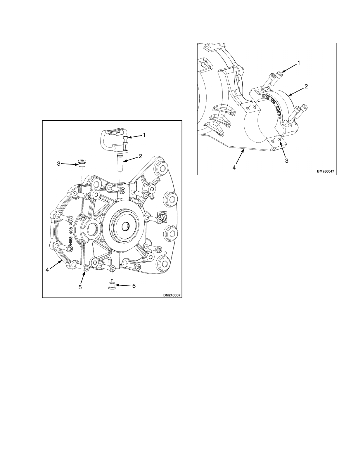
5. Remove capscrew holding sensor to transaxle us-
ing a 5mm Allen wrench. See Figure 5.
6. Pull sensor out of transaxle.
7. Insert new sensor into transaxle.
8. Align screw holes and install capscrew. Tighten
capscrew to 9.5 N•m (84.0 lbf in).
9. Connect sensor wiring harness to main wiring har-
ness.
10. Replace floor plates and floor mat in operator com-
partment.
11. Connect battery, turn key to ON position and test lift
truck for proper operation.
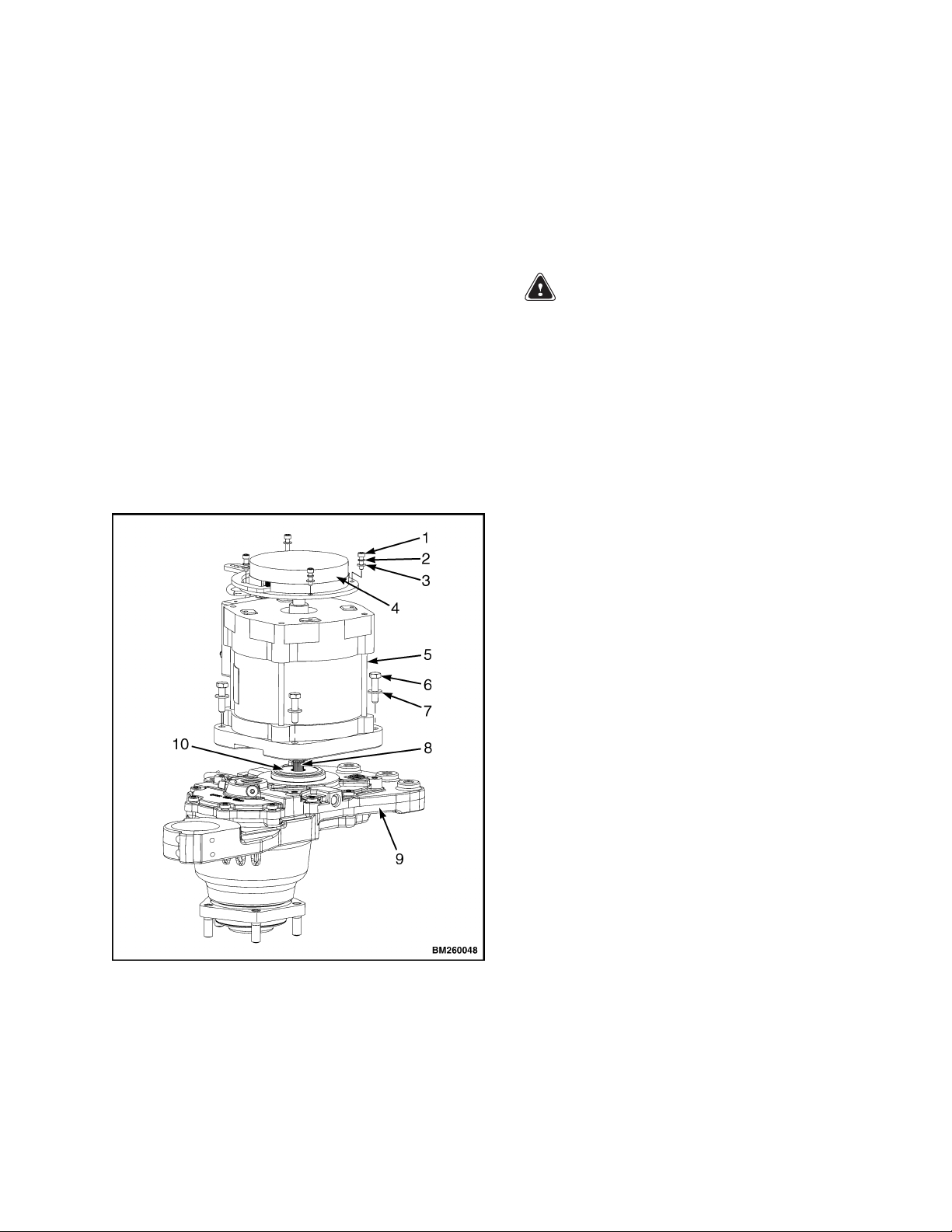
TRUNNION CAP REPAIR
To repair the trunnion cap:
1. Remove load from forks and park lift truck on a level
surface. Adjust mast to a vertical position, then turn
key switch to OFF position and separate battery
connectors.
2. Remove four capscrews holding trunnion cap on
transaxle housing. Remove trunnion cap. See Fig-
ure 6.
3. Wipe away any dirt or grease near mounting holes.
Clean holes with a proper sized tap and tap wrench
as necessary.
6