Yamaha DTT3KSP User manual

SERVICE MANUAL
HAMAMATSU, JAPAN
SERVICE MANUAL
DTT3KSP1: 20080401- オープンプライス
DTT3KSP2: 20080401- オープンプライス
DTT3KSTD1: 20080401- オープンプライス
DTT3KSTD2: 20080401- オープンプライス
ED 011898
You must have a PCY135/PCY155 service manual (ED
011894 )before servicing the PCY135/PCY155.
You must have a RHH135 service manual (ED 011895 )be-
fore servicing the RHH135.
You must have a KP125 service manual (ED 011896 )before
servicing the KP125.
You must have a TP100 service manual (ED 011732 )before
servicing the TP100.
You must have a TP120SD service manual (ED 011733 )be-
fore servicing the TP120SD.
Copyright (c) Yamaha Corporation. All rights reserved. PDF ’08.04
DTXTREMEⅢSPECIAL SET(スペシャルセット)..................... 2
DTXTREMEⅢSTANDARD SET(スタンダードセット)............. 2
COMPLETE ASSEMBLY(同梱品セット)..................................... 3
PARTS LIST(パーツリスト)..................................................... 4
CONTENTS(目次)
PCY135/PCY155 のアフターサービス実施時には、PCY135/
PCY155 (ED 011894 )のサービスマニュアルをご覧ください。
RHH135 の ア フターサービス実施時には、RHH135 (ED
011895 )のサービスマニュアルをご覧ください。
KP125 の ア フ タ ー サ ー ビ ス 実 施 時 に は、KP125 (ED
011896 )のサービスマニュアルをご覧ください。
TP100 の ア フ タ ー サ ー ビ ス 実 施 時 に は、TP100 (ED
011732 )のサービスマニュアルをご覧ください。
TP120SD のアフターサービス実施時には、TP120SD(ED
011733 )のサービスマニュアルをご覧ください。
●PCY135
●PCY155
●RHH135
●KP125
●TP100
●TP120SD
• TP120SD
PADS SET
DTT3KSP/DTT3KSTD
• PCY135
• PCY155
• KP125
• RHH135
• TP100

DTT3KSP/DTT3KSTD
2
DTXTREMEⅢSPECIAL SET(スペシャルセット)
DTXTREMEⅢSTANDARD SET(スタンダードセット)
◎DTXTREMEⅢ(
Trigger Module
(
トリガーモジュール
))※
◎HXR4LD (Rack System (ラックシステム))※
◎DTT3KSP1 (Pads Set (パッドセット))
・PCY135 ×2pcs.
・PCY155 ×1pc.
・RHH135 ×1pc.
・KP125 ×1pc.
・CH750 ×2pcs. (
Cymbal Holder
(
シンバルホルダー
))
・SS662 ×1pc. (
Snare Stand
(
スネアスタンド
))
・Connecting Cable(接続ケーブル)
・Drum Key(ドラムキー)
◎DTT3KSP2 (Pads Set (パッドセット))
・TP120SD ×1pc.
・TP100 ×4pcs.
・CH755 ×1pc. (
Cymbal Holder
(
シンバルホルダー
))
・HS740A ×1pc. (
HI-HAT Stand
(
ハイハットスタンド
))
※: It is not included in the DTT3KSP.
※:DTT3KSPには含まれません。
PCY135
PCY135
DTXTREMEⅢ
PCY155
KP125
TP120SD
RHH135
TP100 TP100
TP100
TP100
※
HS740A
Foot Pedal
(フットペダル)
※
SS662
CH750
HXR4LD※
※
◎DTXTREMEⅢ(
Trigger Module
(
トリガーモジュール
))※
◎RS130 (Rack System (ラックシステム))※
◎DTT3KSTD1 (Pads Set (パッドセット))
・PCY135 ×1pc.
・PCY155 ×1pc.
・RHH135 ×1pc.
・KP125 ×1pc.
・CH750 ×1pc. (
Cymbal Holder
(
シンバルホルダー
))
・SS662 ×1pc. (
Snare Stand
(
スネアスタンド
))
・Connecting Cable(接続ケーブル)
・Drum Key(ドラムキー)
◎DTT3KSTD2 (Pads Set (パッドセット))
・TP120SD ×1pc.
・TP100 ×3pcs.
・CH755 ×1pc. (
Cymbal Holder
(
シンバルホルダー
))
・HS650A ×1pc. (
HI-HAT Stand
(
ハイハットスタンド
))
RS130
TP100
PCY135
DTXTREMEⅢPCY155
KP125
TP120SD
RHH135
TP100 TP100
※
HS650A
SS662
Foot Pedal
(フットペダル)
※
CH750
CH755
※: It is not included in the DTT3KSTD.
※:DTT3KSTDには含まれません。

3
DTT3KSP/DTT3KSTD
COMPLETE ASSEMBLY(同梱品セット)
10 Complete Assembly 1(同梱品セット 1)
10a PCY135
20 Complete Assembly 2(同梱品セット 2)
20a TP100
10b PCY155 10c RHH135 10d KP125 10e SS662
10f CH750
20b TP120SD 20c HS740A
(DTT3KSP only)
20c HS650A
(DTT3KSTD only)
20d CH755
1
Rot Hold Parts Set
(回転ストッパセット)
●Accessories Set
(付属品セット)
2
Clutch Set
(クラッチセット)
2c
2b
2a
2f
2d
2e
2ba
2bb
3Stand Base Set
(スタンドベースセット)
3c
3b
3a
4
9
56
6
78
11
10 Cable Set SP(ケーブルセット SP)
(DTT3KSP1)
10 Cable Set STD(ケーブルセット STD)
(DTT3KSTD1)
PCY135/PCY155 RHH135
KP125
10a 10b 10c 10g 10i 10j 10k 10d 10e 10f 10h 10a 10b 10c 10g 10i 10j 10k 10d 10f
2.5 m Stereo Phone Cable
(2.5mステレオフォーンケーブル)
4.0 m Stereo Phone Cable
(4.0mステレオフォーンケーブル)
2.5 m Stereo Phone Cable
(2.5mステレオフォーンケーブル)
4.0 m Stereo Phone Cable
(4.0mステレオフォーンケーブル)
12
●Spiral Tube(スパイラルチューブ)
13
1a
1b 1c
・DTT3KSP1: 2pcs.
・DTT3KSTD1: 1pc.
・DTT3KSP1: 2pcs.
・DTT3KSTD1: 1pc.
・DTT3KSP1: 3pcs.
・DTT3KSTD1: 2pcs.
9
・DTT3KSP2: 4pcs.
・DTT3KSTD2: 3pcs.

DTT3KSP/DTT3KSTD
4
PARTS LIST(パーツリスト)
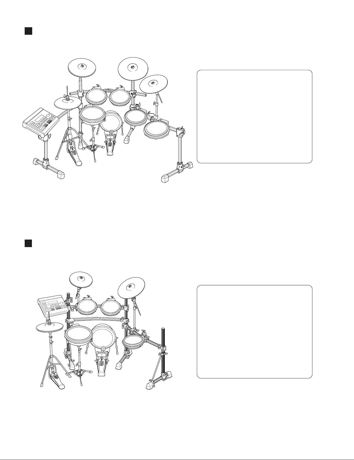
COMPLETE ASSEMBLY 同梱品セット
DTT3KSP/DTT3KSTD
10 -- COMPLETE ASSEMBLY 1 同梱品セット1DTT3KSP (WM92480)
10 -- COMPLETE ASSEMBLY 1 同梱品セット1DTT3KSP O ※1(WM92500)
10 -- COMPLETE ASSEMBLY 1 同梱品セット1DTT3KSTD (WM92520)
10 -- COMPLETE ASSEMBLY 1 同梱品セット1DTT3KSTD O ※1(WM92540)
10a -- OVERALL ASSEMBLY 総組立
DTT3KSP PCY135 (WK36820) 2
10a -- OVERALL ASSEMBLY 総組立
DTT3KSTD PCY135 (WK36820)
10b -- OVERALL ASSEMBLY 総組立
PCY155 (WK72280)
10c -- OVERALL ASSEMBLY 総組立
RHH135 (WK37510)
10d -- OVERALL ASSEMBLY 総組立
KP125 (WK74870)
*10e AAE96880 SNARE STAND スネアスタンドSS662
*10f AAE96890 CYMBAL HOLDER シンバルホルダー DTT3KSP CH750 2
*10f AAE96890 CYMBAL HOLDER シンバルホルダー DTT3KSTD CH750
ACCESSORIES SET 付属品セット
1WK371500 ROT HOLD PARTS SET 回転ストッパセット DTT3KSP PCY135/PCY155 3
1WK371500 ROT HOLD PARTS SET 回転ストッパセット DTT3KSTD PCY135/PCY155 2
1a -- ROTATION HOLD PART 回り止め金具
DTT3KSP PCY135/PCY155 3
(V857830)
1a -- ROTATION HOLD PART 回り止め金具
DTT3KSTD PCY135/PCY155 2
(V857830)
1b WM942400 BOLT 6.0X10 DRUM KEY 角ボルトM6X10 DTT3KSP PCY135/PCY155 3
1b WM942400 BOLT 6.0X10 DRUM KEY 角ボルトM6X10 DTT3KSTD PCY135/PCY155 2
1c WM813000 FELT WASHER D55X18T フェルトワッシャー DTT3KSP PCY135/PCY155 3
1c WM813000 FELT WASHER D55X18T フェルトワッシャー DTT3KSTD PCY135/PCY155 2
2WK739000 CLUTCH SET クラッチセットRHH135
2a -- CLUTCH HEAD クラッチヘッドRHH135 (WK37630)
2b WK734800 ROT HOLD PARTS ASSEMBLY 回転ストッパ組立 RHH135
2ba -- ROT HOLD PARTS WELD 回転ストッパ溶接品 RHH135 (WK73470)
2bb WK738400 STOPPER CAP S BLACK ストッパキャップS RHH135
2c WK377200 NUT 調整ナット
RHH135 2
2d WN784000 WING BOLT M6X9 ウィングボルトRHH135
*2e WN811400 DRUM KEY BOLT M6X12 角ボルトM6X12 RHH135
2f WK378200 FELT WASHER フェルトワッシャー RHH135 2
3WK378800 STAND BASE SET スタンドベースセット RHH135
3a -- STAND BASE スタンドベースRHH135 (WK37840)
3b -- SLIP SHEET BLACK スリップシートRHH135 (WK37850)
3c -- CUSHION BLACK クッション
RHH135 (WK40060)
*4WM027200 SPUR SPRING スパースプリング KP125 2
516033101 FP.HS STOPPER 2 FPHSストッパ2 KP125 2 04
6WM795100 WING BOLT L ウィングボルト(L)KP125 2
7WM795300 BD LEG R RIGHT BD脚(8)−R集成 KP125
8WM795400 BD LEG L LEFT BD脚(8)−L集成 KP125
*9WN553900 WASHER PLAIN 8.0X16X1.0 MFZN2W3 平座みがき丸
KP125 2
10 -- CABLE SET SP ケーブルセットSP DTT3KSP (WM79550)
10 -- CABLE SET STD ケーブルセットSTD DTT3KSTD (WM79560)
*10a WN547000 SNARE CABLE 2.5 m STEREO PHONE スネアケーブル
*10b WN547200 TOM1 CABLE 2.5 m STEREO PHONE タム1ケーブル
*10c WN547300 TOM2 CABLE 2.5 m STEREO PHONE タム2ケーブル
*10d WN547400 TOM3 CABLE 4.0 m STEREO PHONE タム3ケーブル
*10e WN547500 TOM4 CABLE 4.0 m STEREO PHONE タム4ケーブルDTT3KSP
*10f WN547600 RIDE CABLE 4.0 m STEREO PHONE ライドケーブル
*10g WN547700 CRASH1 CABLE 2.5 m STEREO PHONE クラッシュ1ケーブル
*10h WN547800 CRASH2 CABLE 4.0 m STEREO PHONE クラッシュ2ケーブル DTT3KSP
*10i WN547900 HI HAT CABLE 2.5 m STEREO PHONE ハイハットケーブル
*10j WN548000 HH CON CABLE 2.5 m STEREO PHONE HHCONケーブル
*10k WN548100 KICK CABLE 2.5 m STEREO PHONE キックケーブル
*11 WM962100 DRUM KEY 3 ドラムキー 3
12 V8234200 CABLE BAND ケーブルバンド 10 99
13 V8234200 CABLE BAND ケーブルバンドRHH135 99
-- SPIRAL TUBE 2.0 m スパイラルチューブ
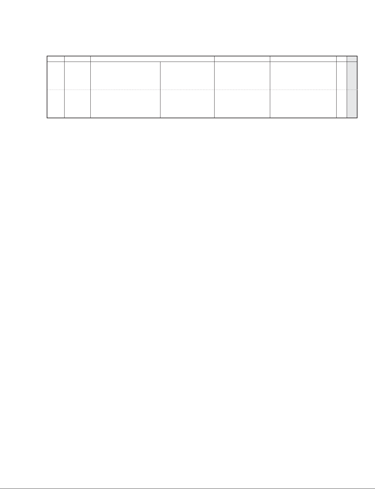
20 -- COMPLETE ASSEMBLY 2 同梱品セット2DTT3KSP (WM92490)
20 -- COMPLETE ASSEMBLY 2 同梱品セット2DTT3KSP O (WM92510)
20 -- COMPLETE ASSEMBLY 2 同梱品セット2DTT3KSTD (WM92530)
20 -- COMPLETE ASSEMBLY 2 同梱品セット2DTT3KSTD O (WM92550)
20a -- OVERALL ASSEMBLY 総組立
DTT3KSP TP100 (WB96710) 4
20a -- OVERALL ASSEMBLY 総組立
DTT3KSP TP100 O (WK88890) 4
20a -- OVERALL ASSEMBLY 総組立
DTT3KSTD TP100 (WB96710)
3
20a -- OVERALL ASSEMBLY 総組立
DTT3KSTD TP100 O (WK88890)
3
REF NO. PART NO. DESCRIPTION 部品名 REMARKS QTY
RANK
*: New Parts RANK: Japan only

5
DTT3KSP/DTT3KSTD
※1: “Environmental protection period mark label (WK53580)” and “Manufacture year/month label (WK75290)” are attached to the Pad of the desti-
nation “O” (for Chinese market).
※1: O 仕向 (中国仕向 )には、PAD 本体に環保期限マークラベル (WK53580)と製造年月ラベル (WK75290)が付加されています。
20b -- OVERALL ASSEMBLY 総組立
TP120SD (WB97090)
20b -- OVERALL ASSEMBLY 総組立
TP120SD O (WK88910)
*20c AAE96790 HI-HAT STAND ハイハットスタンド DTT3KSP HS740A
*20c AAE96800 HI-HAT STAND ハイハットスタンド DTT3KSTD HS650A
*20d AAE96900 CYMBAL HOLDER シンバルホルダー CH755
REF NO. PART NO. DESCRIPTION 部品名 REMARKS QTY
RANK
*: New Parts RANK: Japan only

SERVICE MANUAL
HAMAMATSU, JAPAN
SERVICE MANUAL
20080401-27300
ED 011895
Copyright (c)Yamaha Corporation. All rights reserved. PDF ’08.03
SPECIFICATIONS(総合仕様)......................................2
DISASSEMBLY PROCEDURE(分解手順)...................3
CIRCUIT BOARDS(シート基板図)..............................7
CIRCUIT DIAGRAM(回路図).......................................7
OUTPUT CHECK(出力確認).......................................8
PARTS LIST
CONTENTS(目次)
RHH135
REAL HI-HAT PAD

RHH135
2
WARNING
Components having special characteristics are marked and must be replaced with parts having specification equal to those
originally installed.
IMPORTANT NOTICE
This manual has been provided for the use of authorized Yamaha Retailers and their service personnel. It has been assumed that basic
service procedures inherent to the industry, and more specifically Yamaha Products, are already known and understood by the users,
and have therefore not been restated.
WARNING : Failure to follow appropriate service and safety procedures when servicing this product may result in personal injury,
destruction of expensive components and failure of the product to perform as specified. For these reasons, we advise
all Yamaha product owners that all service required should be performed by an authorized Yamaha Retailer or the
appointed service representative.
IMPORTANT : This presentation or sale of this manual to any individual or firm does not constitute authorization certification,
recognition of any applicable technical capabilities, or establish a principal-agent relationship of any form.
The data provided is belived to be accurate and applicable to the unit(s) indicated on the cover. The research engineering, and service
departments of Yamaha are continually striving to improve Yamaha products. Modifications are, therefore, inevitable and changes in
specification are subject to change without notice or obligation to retrofit. Should any discrepancy appear to exist, please contact the
distributor’s Service Division.
WARNING : Static discharges can destroy expensive components. Discharge any static electricity your body may have accumulated
by grounding yourself to the ground bus in the unit (heavy gauge black wires connect to this bus.)
IMPORTANT : Turn the unit OFF during disassembly and parts replacement. Recheck all work before you apply power to the unit.
WARNING: This product contains chemicals known to the State of California to cause cancer, or birth defects or other reproductive harm.
DO NOT PLACE SOLDER, ELECTRICAL/ELECTRONIC OR PLASTIC COMPONENTS IN YOUR MOUTH FOR ANY REASON WHAT SO EVER!
Avoid prolonged, unprotected contact between solder and your skin! When soldering, do not inhale solder fumes or expose eyes to solder/
flux vapor!
If you come in contact with solder or components located inside the enclosure of this product, wash your hands before handling food.
SPECIFICATIONS(総合仕様)
Size ø329 x 61 (H) mm
(hi-hat clutch not included)
Weight 1.4 kg (hi-hat clutch included)
Sensor System Trigger sensor (piezo) x 1,
switch x 1 (edge)
Controller Type Multi-step Switch
Output jack Standard stereo phone jack x 2
印の部品は、安全を維持するために重要な部品です。交換する場合は、安全のために必ず指定の部品をご使用ください。
外形寸法 φ329X61(H)mm
(ハイハットクラッチ部分を除く)
質量 1.4kg(ハイハットクラッチを含む)
センサー方式 トリガーセンサー(圧電素子)x1、
スイッチ(エッジ)x1
コントローラー方式
多段スイッチ
出力端子 標準ステレオフォーンジャックx2

3
RHH135
Fig.1(図 1)
[100]:PWHeadTappingScrew-B(Bタイト+PWH)
3.0X12MFZN2B3(WM788200)
Fig.2(図 2)
[110]: BindHeadTappingScrew-B(Bタイト+BIND)
3.0X8MFZN2W3(WE774300)
<Bottom view(底から見た図)>
[100] Rear cover
(リアカバー)
[100] [100]
<Bottom view(底から見た図)>
[110B]
JK2 JK1
[110A]
JK2JK1
[A] [C] [D][B]
Jack holder
(ジャックホルダー)
Jack holder
(ジャックホルダー)
Photo 1(写真 1)
DISASSEMBLY PROCEDURE(分解手順)
1. JK1 Circuit Board, JK2 Circuit Board
(Time required: About 1 minute)
1-1 Remove the following screws and remove the rear
cover. (Fig. 1)
[100]: 6 pcs.
1. JK1 シート、JK2 シート(所要時間:約 1 分)
1-1 下記のネジを外してリアカバーを外します。(図 1)
[100]:6 本
1-2 下記のネジを外して JK1 シートを外します。(図 2)
[110A]:1 本
※ ジャックホルダーは JK1 シートの構成部品ではあ
りません。JK1 シートを交換する際は、[A] のナッ
ト 1 個と [C] のワッシャー 1 枚を外してジャック
ホルダーを取り外し、新しい JK1 シートに取り付
けてください。(写真 1)
1-3 下記のネジを外して JK2 シートを外します。(図 2)
[110B]:1 本
※ ジャックホルダーは JK2 シートの構成部品ではあ
りません。JK2 シートを交換する際は、[B] のナッ
ト 1 個と [D] のワッシャー 1 枚を外してジャック
ホルダーを取り外し、新しい JK2 シートに取り付
けてください。(写真 1)
1-2 Remove the following screw and remove the JK1
circuit board. (Fig. 2)
[110A]: 1 pc.
* The jack holder is not part of the JK1 circuit
board. When replacing the JK1 circuit board,
remove the nut marked [A] and washer marked
[C] to remove the jack holder, and install it on
the new JK1 circuit board. (Photo 1)
1-3 Remove the following screw and remove the JK2
circuit board. (Fig. 2)
[110B]: 1 pc.
* The jack holder is not part of the JK2 circuit
board. When replacing the JK2 circuit board,
remove the nut marked [B] and washer marked
[D] to remove the jack holder, and install it on
the new JK2 circuit board. (Photo 1)

RHH135
4
JK2
CN5CN5
Photo 2(写真 2)
Photo 3(写真 3)
Fig.3(図 3)
[120]:PWHeadTappingScrew-B(Bタイト+PWH)
3.0X12MFZN2B3(WM788200)
(RHH アクチュエータ)
RHHactuator
<Bottom view(底から見た図)>
[120] [120]
Sensor board
(センサーボード)
2. RHH Sheet Switch
(Time required: About 2 minutes)
2-1 Remove the rear cover. (See procedure 1-1)
2-2 Disconnect the connector of the JK2 circuit board.
(Photo 2)
2-3 Remove the RHH actuator. (Photo 3)
2-4 Remove the following screws and remove the
sensor board. (Fig. 3)
[120]: 4 pcs.
2. RHH シートスイッチ(所要時間:約 2 分)
2-1 リアカバーを外します。(1-1 項参照)
2-2 JK2 シートのコネクタを外します。(写真 2)
2-3 RHH アクチュエータを外します。(写真 3)
2-4 下記のネジを外してセンサーボードを外します。
(図 3)
[120]:4 本
* The appearance of the JK1 circuit board is slightly different
from that in the picture.
※写真の JK1 シートは、生産品とは若干異なります。

5
RHH135
(RHH シートスイッチ)
RHHsheetswitch
(センサーボード)
Sensorboard
Photo 4(写真 4)
Photo 5(写真 5)
(センサテープ)
Sensor tape
(センサユニット)
Sensor unit
2-5 Remove the RHH sheet switch from the sensor
board. (Photo 4)
3. Sensor Unit
(Time required: About 3 minutes)
3-1 Remove the rear cover. (See procedure 1-1)
3-2 Remove the sensor board. (See procedure 2-4)
3-3 Remove the sensor unit. (Photo 5)
* The sensor unit is secured with the sensor
tape.
* After installing the sensor unit, press it lightly
to make sure that it is secured with the sensor
tape firmly.
2-5 センサーボードから RHH シートスイッチを外し
ます。(写真 4)
3. センサユニット(所要時間:約 3 分)
3-1 リアカバーを外します。(1-1 項参照)
3-2 センサーボードを外します。(2-4 項参照)
3-3 センサユニットを外します。(写真 5)
※ センサユニットはセンサテープで固定されていま
す。
※ 取り付け後は、センサユニットを軽く押さえて、
センサテープでしっかり固定されていることを確
認してください。
* The appearance of the JK1 circuit board is slightly different
from that in the picture.
※写真の JK1 シートは、生産品とは若干異なります。

RHH135
6
JK1
CN2CN2
CN4
CN4
Photo 6(写真 6)
(ラバーパッド)
Rubberpad
Photo 7(写真 7)
(フロントリムシートスイッチ)
RIMsheetswitchF
(リアリムシートスイッチ)
RIMsheetswitchR
(パッドテープ 13R)
PadtapeR
(パッドテープ 13F)
PadtapeF
Photo 8(写真 8)
4. RIM Sheet Switch F, RIM Sheet Switch R
(Time required: About 3 minutes)
4-1 Remove the rear cover. (See procedure 1-1)
4-2 Disconnect the connector of the JK1 circuit board.
(Photo 6)
RIM Sheet Switch F: CN2
RIM Sheet Switch R: CN4
4-3 Remove the rubber pad by stretching edge portion
of the rubber pad with fingers. (Photo 7)
* When installing the rubber pad, be sure to
replace the pad tape 13F (WK370400) and pad
tape 13R (WK370500) with new ones. (Photo 8)
4-4 Remove the RIM sheet switch F and RIM sheet
switch R. (Photo 8)
4. フロントリムシートスイッチ、
リアリムシートスイッチ(所要時間:約 3 分)
4-1 リアカバーを外します。(1-1 項参照)
4-2 JK1 シートのコネクターを外します。(写真 6)
フロントリムシートスイッチ :CN2
リアリムシートスイッチ : CN4
4-3 ラバーパッドの縁を指で広げて、ラバーパッドを
外します。(写真 7)
※ ラバーパッドの取り付け時には、パッドテープ
13F(WK370400)とパッドテープ13R(WK370500)
を必ず新しいテープに貼り替えてください。
(写真8)
4-4 フロントリムシートスイッチ、リアリムシートス
イッチを外します。(写真 8)
* The appearance of the JK1 circuit board is slightly different
from that in the picture.
※写真の JK1 シートは、生産品とは若干異なります。
* The appearance of the JK1 circuit board is slightly different
from that in the picture.
※写真の JK1 シートは、生産品とは若干異なります。

7
RHH135
CIRCUIT BOARDS(シート基板図)
CIRCUIT DIAGRAM(回路図)
JK1 Circuit Board
to RIM sheet switch R
to Sensor unit not installed
PA D
to RIM sheet switch F
to RHH sheet switch
HI-HAT CONTROL
JK2 Circuit Board
Component side(部品側) Component side(部品側)
(*1)
(*1)Voltagevaluediffersdependingonmodels.
Refertopage9.
(*1)モデルによって電圧値が異なります。
9ページを参照してください。
JK2
HI-HAT
CONTROL
to RHH sheet
switch
JK1
not installed
PAD
to RIM sheet
switch R
to Sensor unit
to RIM sheet
switch F
not installed

RHH135
8
OUTPUT CHECK(出力確認)
Stereo cable
PAD output jack
(PAD出力端子)
Cymbal is fitted. (シンバルスタンド装着)
Oscilloscope (オシロスコ−プ)
Check the pad.
(パッドの確認)
Tester (ohm meter)
(テスタ(抵抗計))
Check the rim switch.
(リムスイッチの確認)
ch1
TIP
RING
SLEEVE
PAD
* Take care to avoid damage while holding the product
or by giving it a shock.
製品の保持、打撃で、傷が付かないよう注意します。
TIP
RING
SLEEVE
Pad area (パッド部)
[F]
Rimarea(リム部)
[R]
Rimarea(リム部)
1. Checking Pad Area For Output
Check for phase (polarity) by tapping the pad area.
(Check for the change in the crest value according to
whether the output is high or low)
2. Checking Rim Area for Output ([F] and [R])
Check that the tester (ohm meter) points to approxi-
mately 10 Ωwhen the rim area is lightly picked up.
1. パッド部出力の確認
パッド部を叩いて位相 ( 極性 ) の確認を行います。
(強弱で波高値の変化を確認してください)
2.リム部出力の確認([F]および [R])
リム部を軽くつまんだ時、テスタ(抵抗計)が約
10 Ωとなることを確認します。
NG
OK
BA
Output V
(出力 V)
Output V
(出力 V)
Probe 10 : 1 0.2 V/DIV, 5 mS 0.2 V/DIV, 5 mS
ch1: Signal waveform of pad.
(ch1:パッド部信号波形)
ch1: Signal waveform of pad.
(ch1:パッド部信号波形)
1st wave(第 1 波)
1st wave(第 1 波)
Time t
(時間t)
Time t
(時間t)
Preparations
• Oscilloscope
• Tester
• Connect cable
• Drum stick
準備するもの
・ オシロスコープ
・ テスタ(抵抗レンジ)
・ 接続ケーブル
・ ドラムスティック
Note: Be sure to tap the YAMAHA logo
for checking waveform.
注) 波形チェックは必ず YAMAHA ロゴ
上を叩いてください。

9
RHH135
3. Checking HI-HAT Control
Pushing the clutch head downward turns on the
switch.
The force (F) used then brings about the change in the
ON atatus of the switches (A to E).
[Checking Single RHH135]
Connect the stereo phone cable to the HI-HAT Con-
trol terminal. Pusing the clutch head downward brings
about a change in the resistance between RINGS and
SLEEVE.
3.HI-HATCONTROL の確認
クラッチヘッドを下方に押すとスイッチが入ります。
加える力(F)によって ON となるスイッチ(A 〜 E)
の状態が変化します。
[RHH135 単体で確認する場合 ]
ステレオホーンケーブルを HI-HATCONTROL 端子
に接続します。クラッチヘッドを下方に押すと RING-
SELEEVE 間の抵抗値が変化します。
Clutch head
(クラッチヘッド)
Tester (ohm meter)
(テスタ(抵抗レンジ))
HI-HAT
CONTROL
TIP
RING
SLEEVE
B: ON (64.6 – 71.4 KΩ)
A: ON (207.1 – 228.9 KΩ)
C: ON (19.95 – 22.05 KΩ)
D: ON (10.45 – 11.55 KΩ)
E: ON (0.95 – 1.05 KΩ)
F
70 KΩ
220 KΩ
20 KΩ
10 KΩ
1 KΩ
OPEN
(Switch: OFF)
RESISTANCE
Switch: OFF
Switch
(スイッチ)
Switch: ON
F
HI-HAT CONTROL
[Checking by Connecting with Trigger Module]
Connecting with the trigger module supplies the volt-
age Vcc from the TIP, causing variations in the RING
voltage according to the status of the switches A to E.
In case of DTXTREME III, the following voltage value
is as follows. (Voltage value differs depending on mod-
els.)
[トリガーモジュールと接続して確認する場合]
トリガーモジュールと接続した場合は、TIP から電圧
Vcc が供給されスイッチ A 〜 E の状態により RING で
の電圧が変化します。DTXTREMEIII の場合は下図の
電圧値となります。(モデルによって電圧値は異なり
ます。)
2 TIP
1 SLEEVE
3 RING
A: ON 2.32 – 2.86 V
1.52 – 1.98 V
0.70 – 0.96 V
0.40 – 0.56 V
0 – 0.04 V
C: ON
D: ON
E: ON
B: ON
B
150 KR5
C
47 KR6
D
10 KR7
E
10 KR8
A150 KR4
R3
1K
HI-HAT
CONTROL
Vcc=3.3 V or Vcc=5.0 V
Vcc=3.3 V
• DTXPRESS
II
• DTXPRESS
• DTXPRESS
III
• DTXPLORER
• DTXTREME
III
etc.
F
Vcc=5.0 V
• DTXTREME
• DTXTREME
II
S
etc.
• DTXPRESS
IV
(参考)
(Reference)

RHH135
10
A
B
C
D
E

WARNING
Components having special characteristics are marked and must be replaced with parts having
specification equal to those originally installed.
• The numbers “QTY” show quantities for each unit.
• The parts with “--” in “PART NO.” are not available as spare parts.
• This mark “ } ” in the REMARKS column means these parts are interchangeable.
• The second letter of the shaded ( ) part number is O, not zero.
• The second letter of the shaded ( ) part number is I, not one.
• 部品価格ランクは、変更になることがあります。
• QTY 欄に記されている数字は、各ユニット当たりの使用個数です。
• PARTNO. が--の部品は、サービス用部品として準備されておりません。
• REMARKS 欄の「 } 」マークの部品は、併用部品です。
• 網掛けの付いた PARTNO.の 2 番目の文字は「ゼロ」ではなく、「オー」です。
• 網掛けの付いた PARTNO.の 2 番目の文字は「イチ」ではなく、「アイ」です。
Notes : DESTINATION ABBREVIATIONS
A : Australian model
B : British model
C : Canadian model
D : German model
E : European model
F : French model
H : North European model
I : Indonesian model
J : Japanese model
K : Korean model
M: South African model
O : Chinese model
Q : South-east Asia model
T : Taiwan model
U : U.S.A. model
V : General export model (110V)
W: General export model (220V)
N,X: General export model
Y : Export model
印の部品は、安全を維持するために重要な部品です。交換する場合は、安全のために必ず指定の部品を
ご使用ください。
CONTENTS(目次)
OVERALL ASSEMBLY(総組立)
...............................................2
ELECTRICAL PARTS(電気部品)
.............................................4
PARTS LIST
RHH135
REAL HI-HAT PAD

2
RHH135
OVERALL ASSEMBLY(総組立)
1
●ACCESSORIES(付属品)
Stereo cable
(ステレオケーブル)
Cable band
(ケーブルバンド)
Clutch set(クラッチセット)
2Stand base set
(スタンドベースセット)
1d
2b
2c
2a
1e
1c
1bb
50b
P20
P40
P60
P50
P10
60
80
70
90
100
120
30
110
20a
40a
40b
110
50a
1a
1f
1ba
Pad assembly
(パッド組立)
10
Jack assembly 1
(ジャック組立1)
40
Jack assembly 2
(ジャック組立2)
50
Sensor unit
(センサーユニット)
20
P30

3
RHH135
OVERALL ASSEMBLY 総組立
RHH135
-- Overall Assembly 総組立
(WK37510)
10 -- Pad Assembly パッド組立
(WK37520)
*20 WN281300 Sensor Unit センサユニット
20a -- Connector Assembly PAD KR 2P PAD束線
(WK37070)
*30 WK400700 Sensor Tape Black センサテープ
40 -- Jack Assembly 1 ジャック組立1 (WK37530)
*40a WK375500 Circuit Board JK1 JKシート1
*40b WK371100 Holder, Jack ジャックホルダー
50 -- Jack Assembly 2 ジャック組立2 (WK37560)
*50a WK375800 Circuit Board JK2 JKシート2
*50b WK371100 Holder, Jack ジャックホルダー
*60 WK375900 Sensor Board Black センサーボード
*70 WK376000 RHH Actuator Black RHHアクチュエータ
*80 WK376100 RHH Sheet Switch RHHシートSW
*90 WK379800 Rear Cover Black リアカバー
*100 WM788200 PW Head Tapping Screw-B 3.0X12 MFZN2B3 Bタイト+PWH 6
110 WE774300 Bind Head Tapping Screw-B 3.0X8 MFZN2W3 Bタイト+BIND 201
*120 WM788200 PW Head Tapping Screw-B 3.0X12 MFZN2B3 Bタイト+PWH 4
-- Pad Assembly パッド組立
(WK37520)
*P10 WK368500 Body Gray ボディ13
*P20 WK368700 Rubber Pad Dark Gray ラバーパッド13
*P30 WN578500 RIM Sheet Switch F FRONT リムシートSW13F
*P40 WN578600 RIM Sheet Switch R REAR リムシートSW13R
*P50 WK370400 Pad Tape F FRONT パッドテープ13F
*P60 WK370500 Pad Tape R REAR パッドテープ13R
ACCESSORIES 付属品
*1WK739000 Clutch Set クラッチセット
1a -- Clutch Head クラッチヘッド (WK37630)
*1b WK734800 Rot Hold Parts Assembly 回転ストッパ組立
1ba -- Rot Hold Parts 回転ストッパ溶接品 (WK73470)
*1bb WK738400 Stopper Cap S Black ストッパキャップS
*1c WK377200 Nut 調整ナット 2
*1d WN784000 Wing Bolt M6X9 ウィングボルト
1e WN811400 Bolt M6X12 角ボルトM6X12 03
*1f WK378200 Felt Washer フェルトワッシャー 2
*2WK378800 Stand Base Set スタンドベースセット
2a -- Stand Base スタンドベース (WK37840)
2b -- Slip Sheet Black スリップシート (WK37850)
2c -- Cushion Black クッション
(WK40060)
WC158000 Stereo Cable PHONE 4.0m ST L-S ステレオケーブル 207
V8234200 Cable Band ケーブル バンド
REF NO. PART NO. DESCRIPTION 部品名 REMARKS QTY
RANK
*: New Parts RANK: Japan only

4
RHH135
ELECTRICAL PARTS(電気部品)
JK1 and JK2
ELECTORICAL PARTS 電気部品
RHH135
*WK375500 Circuit Board JK1 JKシート1
(WK37540)(X8919C0)
*WK375800 Circuit Board JK2 JKシート2
(WK37570)(X8920A0)
*WK375500 Circuit Board JK1 JKシート1
(WK37540)(X8919C0)
CN1 VB389800 Base Post Connector PH 2P TE ベースポスト 01
CN2 VU552200 Connector, FPC 5597 8P SE FPCコネクタ 01
CN4 VU552200 Connector, FPC 5597 8P SE FPCコネクタ 01
JK1 V6177700 Phone Jack ST. HTJ-064-12D ホーンジャックPAD 03
R1 HF757680 Carbon Resistor 68.0K 1/4 J AX TP カーボン抵抗 01
R2 -- Jumper Wire 0.55 ジャンパー線
(VA07890)
R3 -- Jumper Wire 0.55 ジャンパー線
(VA07890)
R4 HF757680 Carbon Resistor 68.0K 1/4 J AX TP カーボン抵抗 01
R5 HF757510 Carbon Resistor 51.0K 1/4 J AX TP カーボン抵抗 01
*WK375800 Circuit Board JK2 JKシート2
(WK37570)(X8920A0)
C2 VD930900 Semiconductive Cera. Cap. 0.1000 25V M RX TP 半導体セラコン 01
CN5 V9639200 Connector, FPC FPC 17P SE FPC用コネクター
JK2 V6177700 Phone Jack ST. HTJ-064-12D ホーンジャックHI-HAT CONTROL 03
R3 HF756100 Carbon Resistor 1.0K 1/4 J AX TP カーボン抵抗 01
R4 HF758150 Carbon Resistor 150.0K 1/4 J AX TP カーボン抵抗 01
R5 HF758150 Carbon Resistor 150.0K 1/4 J AX TP カーボン抵抗 01
R6 HF757470 Carbon Resistor 47.0K 1/4 J AX TP カーボン抵抗 01
R7 HF757100 Carbon Resistor 10.0K 1/4 J AX TP カーボン抵抗 01
R8 HF757100 Carbon Resistor 10.0K 1/4 J AX TP カーボン抵抗 01
REF NO. PART NO. DESCRIPTION 部品名 REMARKS QTY
RANK
*: New Parts RANK: Japan only

SERVICE MANUAL
HAMAMATSU, JAPAN
SERVICE MANUAL
20080401-36750
ED 011896
Copyright (c)Yamaha Corporation. All rights reserved. PDF ’08.03
SPECIFICATIONS(総合仕様)......................................2
DISASSEMBLY PROCEDURE(分解手順)...................3
CIRCUIT BOARD(シート基板図)................................6
CIRCUIT DIAGRAM(回路図).......................................6
INSPECTIONOFFUNCTION(機能検査)....................7
PARTS LIST
CONTENTS(目次)
KP125
KICK PAD
Other manuals for DTT3KSP
1
This manual suits for next models
1
Table of contents
Other Yamaha Drum manuals

Yamaha
Yamaha BP80 User manual

Yamaha
Yamaha DTX-PRO User manual

Yamaha
Yamaha MR10 User manual

Yamaha
Yamaha DD-3 User manual

Yamaha
Yamaha RS40 User manual

Yamaha
Yamaha RM-50 User manual

Yamaha
Yamaha RX-15 User manual

Yamaha
Yamaha DD-10 User manual

Yamaha
Yamaha DTX500 User manual

Yamaha
Yamaha PCY135 User manual

Yamaha
Yamaha DTXPLORER User manual

Yamaha
Yamaha DD65 YDD-60

Yamaha
Yamaha DTXTREME User manual

Yamaha
Yamaha DTXTREME IIs User manual

Yamaha
Yamaha DD-6 User manual

Yamaha
Yamaha KP120 User manual

Yamaha
Yamaha DTX RS500 User manual

Yamaha
Yamaha DTX920K User manual

Yamaha
Yamaha CSM-1345A User manual

Yamaha
Yamaha CB832C User manual