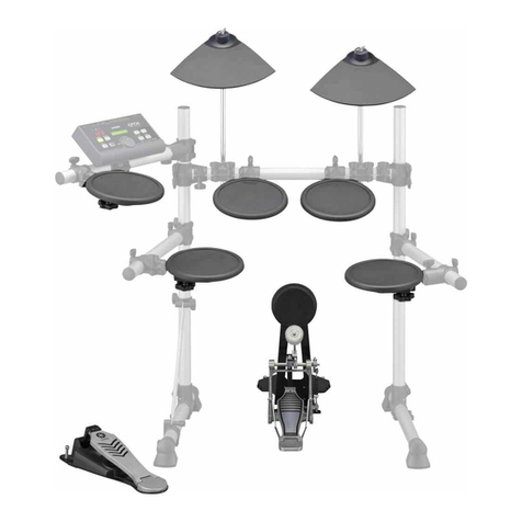
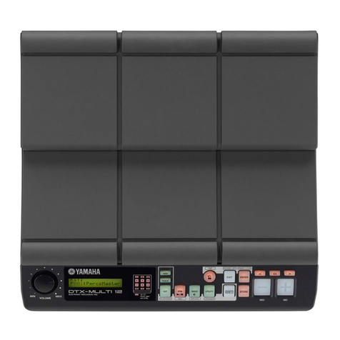
Yamaha DTXPRESS IV User manual

SERVICE MANUAL
Copyright (c) Yamaha Corporation. All rights reserved. PDF ’06.12
ED 011849
■CONTENTS(目次)
SPECIFICATIONS(総合仕様)................................................ 3/4
PANEL LAYOUT(パネルレイアウト)...................................... 5
CONNECTING THE PADS(パッドの接続).............................. 7
CIRCUIT BOARD LAYOUT & WIRING
(ユニットレイアウト&結線図)............................................. 8
DISASSEMBLY PROCEDURE(分解手順)............................... 9
LSI PIN DESCRIPTION(LSI端子機能表)............................... 11
IC BLOCK DIAGRAM(ICブロック図).................................... 12
CIRCUIT BOARDS(シート基板図)........................................ 14
TEST PROGRAM(テストプログラム).............................. 18/31
FACTORY SETTING(出荷時の設定)................................. 30/43
ERROR MESSAGES(エラーメッセージ).............................. 44
SYSTEM BOOTING FLOWCHART
(起動フローチャート).................................................... 45/46
MIDI IMPLEMENTATION CHART.......................................... 47
MIDI DATA FORMAT ............................................................. 48
PARTS LIST
BLOCK DIAGRAM(ブロックダイアグラム)
OVERALL CIRCUIT DIAGRAM(総回路図)
20061215-オープンプライス HAMAMATSU, JAPAN
DRUMTRIGGER MODULE
w
w
w
.
x
i
a
o
y
u
1
6
3
.
c
o
m
Q
Q
3
7
6
3
1
5
1
5
0
9
9
2
8
9
4
2
9
8
T
E
L
1
3
9
4
2
2
9
6
5
1
3
9
9
2
8
9
4
2
9
8
0
5
1
5
1
3
6
7
3
Q
Q
TEL 13942296513 QQ 376315150 892498299
http://www.xiaoyu163.com
2
DTXPRESS
IMPORTANT NOTICE
This manual has been provided for the use of authorized Yamaha Retailers and their service personnel. It has been
assumed that basic service procedures inherent to the industry, and more specifically Yamaha Products, are already
known and understood by the users, and have therefore not been restated.
WARNING : Failure to follow appropriate service and safety procedures when servicing this product may result in
personal injury, destruction of expensive components and failure of the product to perform as
specified. For these reasons, we advise allYamaha product owners that all service required should
be performed by an authorizedYamaha Retailer or the appointed service representative.
IMPORTANT : This presentation or sale of this manual to any individual or firm does not constitute authorization,
certification, recognition of any applicable technical capabilities, or establish a principal-agent
relationship of any form.
The data provided is believed to be accurate and applicable to the unit (s) indicated on the cover.The research engineering,
and service departments of Yamaha are continually striving to improveYamaha products. Modifications are, therefore,
inevitable and changes in specification are subject to change without notice or obligation to retrofit.Should any discrepancy
appear to exist, please contact the distributor’s Service Division.
WARNING : Static discharges can destroy expensive components. Discharge any static electricity your body
may have accumulated by grounding yourself to the ground bus in the unit (heavy gauge black wires
connect to this bus).
IMPORTANT : Turn the unit OFF during disassembly and parts replacement. Recheck all work before you apply
power to the unit.
WARNING : CHEMICAL CONTENT NOTICE !
The solder used in the production of this product contains LEAD. In addition, other electrical/electronic and/or plastic
(where applicable) components may also contain traces of chemicals found by the California Health and Welfare Agency
(and possibly other entities) to cause cancer and/or birth defects or other reproductive harm.
DO NOT PLACE SOLDER, ELECTRICAL/ELECTRONIC OR PLASTIC COMPONENTS IN YOUR MOUTH FOR ANY
REASON WHAT SO EVER!
Avoid prolonged, unprotected contact between solder and your skin! When soldering, do not inhale solder fumes or expose
eyes to solder/flux vapor!
If you come in contact with solder or components located inside the enclosure of this product, wash your hands before
handling food.
■WARNING
Components having special characteristics are marked Zand must be replaced with parts having specification equal to
those originally installed.
Z印の部品は、安全を維持するために重要な部品です。交換する場合は、安全のために必ず指定の部品をご使用ください。
■SAVING DATA
• Never attempt to turn off the power while data is being
written to Flash ROM (while a "now storing..." message
is shown).Turning the power off in this state results in
loss of all user data and may cause the system to freeze
(due to corruption of data in the Flash ROM).This means
that this instrument may not be able to start up properly,
even when turning the power on next time.
■データの保存
フラッシュROMへの書き込み中(画面に「nowstoring...」と表示
されます)に、絶対に電源を切らないでください。ユーザーメモ
リー上のデータが失われたりシステムデータが壊れたりして、次
に電源を入れたときに正常に起動しなくなる恐れがあります。
w
w
w
.
x
i
a
o
y
u
1
6
3
.
c
o
m
Q
Q
3
7
6
3
1
5
1
5
0
9
9
2
8
9
4
2
9
8
T
E
L
1
3
9
4
2
2
9
6
5
1
3
9
9
2
8
9
4
2
9
8
0
5
1
5
1
3
6
7
3
Q
Q
TEL 13942296513 QQ 376315150 892498299
http://www.xiaoyu163.com
3
DTXPRESS
■SPECIFICATIONS
Tone Genera-
tor block Tone Generator AWM2
Maximum Polyphony 32
Voices 427 Drum, Percussion Voices
22 Keyboard Voices
Drum Kits Preset: 50
User: 20
Effects Reverb x 19 types, Master EQ
Trigger Trigger Setups Preset: 7
User: 4
Pad Controller Snares adjustment, Tuning,Tempo
Pad Functions Drum Kit INC/DEC, Click Set INC/DEC, Tempo INC/DEC, Click ON/OFF
Pad Songs Start/Stop, Chase, Cut Off
3 songs (max.) can be played simultaneously.
Sequencer Note Capacity Approx.16,000 notes
Note Resolution 96 parts per quarter note
Recording Type Real Time Replace
Track 1
Songs 3 Demo Songs
41 Practice Songs
19 Pad Songs
20 User Songs
Metronome Tempo 30–300 beats/minute, Tap Tempo function
Beat 1–9
Timing Accent, Quarter note, Eighth note, Sixteenth note, Triplet
Click Sound Sets Preset: 6
User: 1
Click Sets 30
Click Timer 0–600 seconds (in 30-second steps)
Training Functions Measure Break, Groove Check, Rhythm Gate
Others Controls Buttons: DRUMKIT, CLICK, SONG >/ , SHIFT, <, >, ON/OFF, SAVE/ENTER
Controllers:Volume, Jog Dial
Displays 16 characters x 2 lines backlit LCD, 7-segment LED (3-digit), Tempo LED x 2
Connectors Trigger inputs 1, 5, 6, 7 (stereo phone jack L: trigger input, R: rim switch)
Trigger inputs 2, 3, 4, 8 (stereo phone jack L: trigger input, R: trigger input)
HI HAT CONTROL (stereo phone jack)
OUTPUT L/MONO, R (mono phone jack)
PHONES (stereo phone jack), AUX IN (stereo mini jack)
MIDI OUT, DC IN
Power Consumption 13.0 W
Dimensions (W x D x H) 252 x 147 x 52 mm (9-15/16" x 5-13/16" x 2-1/16")
Weight 898 g (2 lbs.)
Accessories Yamaha AC power adaptor (PA-3C), Module stand, Module stand fastening screws x 2
Owner's Manual
w
w
w
.
x
i
a
o
y
u
1
6
3
.
c
o
m
Q
Q
3
7
6
3
1
5
1
5
0
9
9
2
8
9
4
2
9
8
T
E
L
1
3
9
4
2
2
9
6
5
1
3
9
9
2
8
9
4
2
9
8
0
5
1
5
1
3
6
7
3
Q
Q
TEL 13942296513 QQ 376315150 892498299
http://www.xiaoyu163.com

4
DTXPRESS
■ 総合仕様
音源部 音源方式 AWM2
最大同時発音数 32音
ボイス数 ドラム/パーカッション音色: 427種類
キーボード音色: 22種類
ドラムキット数 プリセット: 50キット
ユーザー: 20キット
エフェクター リバーブx 19タイプ、マスターEQ
トリガー トリガーセットアップ プリセット: 7種類
ユーザー: 4種類
パッドコントローラー スナッピー調節、チューニング、テンポ
パッドファンクション ドラムキットINC/DEC、クリックセットINC/DEC、テンポINC/DEC
クリックON/OFF
パッドソング スタート/ストップ、チェイス、カットオフ
最大3曲同時再生可能
シーケンサー シーケンサー容量 約16,000音
音符分解能 4分音符/96
レコーディング方式 リアルタイムリプレース
トラック数 1
ソング数 デモソング: 3曲
練習曲: 41曲
パッドソング: 19曲
ユーザー: 20曲
メトロノーム テンポ 30〜300/分、タップテンポ機能
ビート 1〜9
タイミング アクセント、4分音符、8分音符、16分音符、3連符
クリックサウンドセット プリセット: 6種類
ユーザー: 1種類
クリックセット 30種類
クリックタイマー 0〜600秒(30秒間隔)
練習機能 メジャーブレイク、グルーブチェック、リズムゲート
その他 操作子 ボタン: DRUMKIT、CLICK、SONG
>/■、SHIFT、
<、
>、 ON/OFF、
SAVE/ENTER
コントローラー: ボリューム、ジョグダイアル
ディスプレイ 16文字×2行バックライト付LCD、3桁7セグメントLED、テンポ確認用LED×2
接続端子 トリガー入力1、5、6、7(ステレオ標準フォーン端子L:トリガー、R:リムスイッチ)
トリガー入力2、3、4、8(ステレオ標準フォーン端子L:トリガー、R:トリガー)
HI HAT CONTROL (ステレオ標準フォーン端子)
OUTPUT L/MONO、R (標準フォーン端子)
PHONES (ステレオ標準フォーン端子)、AUX IN (ステレオミニ端子)
MIDI OUT、DC IN
消費電力 13.0W
寸法 252(W) x 147(D) x 52(H) mm
質量 898g
付属品 電源アダプター(PA-3C)、保証書、取扱説明書
モジュールホルダー、モジュールホルダー止めネジ:2本
w
w
w
.
x
i
a
o
y
u
1
6
3
.
c
o
m
Q
Q
3
7
6
3
1
5
1
5
0
9
9
2
8
9
4
2
9
8
T
E
L
1
3
9
4
2
2
9
6
5
1
3
9
9
2
8
9
4
2
9
8
0
5
1
5
1
3
6
7
3
Q
Q
TEL 13942296513 QQ 376315150 892498299
http://www.xiaoyu163.com

5
DTXPRESS
■PANEL LAYOUT(パネルレイアウト)
Top Panel(トップパネル)
qDrum Kit button (DRUM KIT)
wClick button (CLICK)
eSong button (SONG >/■)
rShift button (SHIFT)
tSelect buttons (<, >)
yClick ON/OFF button ( ON/OFF)
uSave/Enter button (SAVE/ENTER)
iClick lamp
oLED display
!0 LCD display
!1 Jog dial
qドラムキットボタン(DRUMKIT)
wクリックボタン(CLICK)
eソングボタン(SONG>/■)
rシフトボタン(SHIFT)
tセレクトボタン(<、>)
yクリックON/OFF ボタン( ON/OFF)
uセーブ/ エンターボタン(SAVE/ENTER)
iクリックランプ
oLEDディスプレイ
!0LCDディスプレイ(画面)
!1ジョグダイアル
w
w
w
.
x
i
a
o
y
u
1
6
3
.
c
o
m
Q
Q
3
7
6
3
1
5
1
5
0
9
9
2
8
9
4
2
9
8
T
E
L
1
3
9
4
2
2
9
6
5
1
3
9
9
2
8
9
4
2
9
8
0
5
1
5
1
3
6
7
3
Q
Q
TEL 13942296513 QQ 376315150 892498299
http://www.xiaoyu163.com
6
DTXPRESS
Rear Panel(リアパネル)
!2 MIDI OUT jack
!3 Trigger Input jacks (qSNARE thru iKICK/9)
!4 Hi-hat controller jack (HI HAT CONTROL)
!5 Output jacks (OUTPUT L/MONO, R)
!6 Headphones jack (PHONES)
!7 AUX IN jack
!8 Master Volume (VOLUME)
!9 Power supply jack (DC IN 12V)
@0 Cable clip
@1 POWER Switch (
?
STANDBY/
>
ON)
!2MIDIOUT端子
!3トリガー入力端子(qSNARE〜 iKICK/9)
!4ハイハットコントロール端子(HIHATCONTROL)
!5出力端子(OUTPUTL/MONO、R)
!6ヘッドフォン端子(PHONES)
!7AUXIN端子
!8マスターボリューム(VOLUME)
!9電源端子(DCIN12V)
@0コードフック
@1電源スイッチ(
?
STANDBY/
>
ON)
w
w
w
.
x
i
a
o
y
u
1
6
3
.
c
o
m
Q
Q
3
7
6
3
1
5
1
5
0
9
9
2
8
9
4
2
9
8
T
E
L
1
3
9
4
2
2
9
6
5
1
3
9
9
2
8
9
4
2
9
8
0
5
1
5
1
3
6
7
3
Q
Q
TEL 13942296513 QQ 376315150 892498299
http://www.xiaoyu163.com

8
DTXPRESS
■CIRCUIT BOARD LAYOUT &WIRING(ユニットレイアウト&結線図)
DM
PN
DM
CN3 22P
CN305 22P
CN6 22P
CN304 22P
CN4 22PCN5 3P
CN303 22PCN306 3P
CN3 22PCN6 22PCN4 22PCN5 3P
to PN-CN305
to PN-CN304
to PN-CN303to PN-CN306
InsideView 1(内部図1)
InsideView 2(内部図2)
Component side
(部品側)
Pattern side
(パターン側)
Pattern side
(パターン側)
w
w
w
.
x
i
a
o
y
u
1
6
3
.
c
o
m
Q
Q
3
7
6
3
1
5
1
5
0
9
9
2
8
9
4
2
9
8
T
E
L
1
3
9
4
2
2
9
6
5
1
3
9
9
2
8
9
4
2
9
8
0
5
1
5
1
3
6
7
3
Q
Q
TEL 13942296513 QQ 376315150 892498299
http://www.xiaoyu163.com

9
DTXPRESS
■DISASSEMBLY PROCEDURE(分解手順)
1. Front Case (Time required: About 1 minute)
Remove the three (3) screws marked [160A]. The front
case can then be removed. (Fig. 1)
1. フロントケース(所要時間:約 1 分 )
[160A]のネジ3本を外して、フロントケースを外し
ます。(図1)
Fig. 2(図2)
[160C],[160D],[160E]: BindHeadTappingScrew-B(Bタイト+BIND)3.0X12MFZN2B3(WE998100)
<Bottom view>(底面)
<Rear view>(後面)
2. Bottom Case
(Time required: About 2 minutes)
2-1 Remove the front case. (See procedure 1)
2-2 Remove the four (4) screws marked [160B]. (Fig. 1)
2-3 Remove the three (3) screws marked [160C]. The
bottom case can then be removed. (Fig. 2)
2. ボトムケース(所要時間:約 2 分 )
2-1 フロントケースを外します。(1項参照)
2-2 [160B]のネジ4本を外します。(図1)
2-3 [160C]のネジ3本を外して、ボトムケースを外しま
す。(図2)
[160A]
[160B]
Front case(フロントケース)
Bottom case(ボトムケース)
Cord column
(コードコラム)[160C][160C][160C]
[160D] [160E] [160E]
Encoder knob(エンコーダツマミ)
[160A],[160B]: BindHeadTappingScrew-B(Bタイト+BIND)3.0X12MFZN2B3(WE998100)
Fig. 1(図1)
注意事項
フラットケーブルの表・裏を逆に差し込まないように
注意して取り付けてください。(図A)
Caution:
Pay attention not to insert and install the cable to
the connector inversely. (Fig. A)
Front Side (Printed Side)
表面(印刷面) Back Side
裏面
Fig. A(図A)
w
w
w
.
x
i
a
o
y
u
1
6
3
.
c
o
m
Q
Q
3
7
6
3
1
5
1
5
0
9
9
2
8
9
4
2
9
8
T
E
L
1
3
9
4
2
2
9
6
5
1
3
9
9
2
8
9
4
2
9
8
0
5
1
5
1
3
6
7
3
Q
Q
TEL 13942296513 QQ 376315150 892498299
http://www.xiaoyu163.com
10
DTXPRESS
Fig. 3(図3)
[180]:BindHeadTappingScrew-B(Bタイト+BIND)3.0X8MFZN2W3(WE774300)
[190]:FlatWasher(平座みがき丸)3.0X8X0.5MFZN2W3(WF577000)
3. DM Circuit Board
(Time required: About 3 minutes)
3-1 Remove the front case. (See procedure 1)
3-2 Remove the bottom case. (See procedure 2)
3-3 Remove the screw marked [160D]. (Fig. 2)
3-4 Remove the locking spacer. The DM circuit board can
then be removed. (Fig. 3)
3. DMシート(所要時間:約 3 分 )
3-1 フロントケースを外します。(1項参照)
3-2 ボトムケースを外します。(2項参照)
3-3 [160D]のネジ1本を外します。(図2)
3-4 ロッキングスペーサを外して、DMシートを外しま
す。(図3)
DM
Locking spacer
(ロッキングスペーサ)
4. PN Circuit Board
(Time required: About 5 minutes)
4-1 Remove the front case. (See procedure 1)
4-2 Remove the bottom case. (See procedure 2)
4-3 Remove the DM circuit board. (See procedure 3)
4-4 Remove the encoder knob. (Fig. 2)
4-5 Remove the two (2) screws marked [160E]. (Fig. 2)
4-6 Remove the eight (8) screws marked [180] and the
two (2) flat washers marked [190]. The PN circuit
board can then be removed. (Fig. 4)
* When mounting the PN circuit board, always start by
tightening screws (with washers)
q
,
w
in sequence.
(Fig. 4)
4. PNシート(所要時間:約 5 分 )
4-1 フロントケースを外します。(1項参照)
4-2 ボトムケースを外します。(2項参照)
4-3 DMシートを外します。(3項参照)
4-4 エンコーダツマミを外します。(図2)
4-5 [160E]のネジ2本を外します。(図2)
4-6 [180]のネジ8本と[190]の平座みがき丸2個を外し
て、PNシートを外します。(図4)
※ PNシートを取り付ける際、まず最初にq、wのネジ(ワッ
シャー含む)を順に締めます。(図4)
Fig. 4(図4)
DM
PN
CN3 22P
CN305 22P
CN6 22P
CN304 22P
CN4 22PCN5 3P
CN303 22PCN306 3P
[180]
[180], [190][180], [190]
[180]
[180]
[180]
[180]
[180]
1
2
w
w
w
.
x
i
a
o
y
u
1
6
3
.
c
o
m
Q
Q
3
7
6
3
1
5
1
5
0
9
9
2
8
9
4
2
9
8
T
E
L
1
3
9
4
2
2
9
6
5
1
3
9
9
2
8
9
4
2
9
8
0
5
1
5
1
3
6
7
3
Q
Q
TEL 13942296513 QQ 376315150 892498299
http://www.xiaoyu163.com
11
DTXPRESS
■LSI PIN DESCRIPTION(LSI 端子機能表)
1 ICN I Initial clear 85 CMA3 O Program address bus
2 RFCLKI I PLL Clock 86 CMA8 O Program address bus
3 TM2 I PLL Control 87 CMA2 O Program address bus
4 AVDD_PLL Power supply 88 CRD O read signal
5 AVSS_PLL Ground 89 CMA1 O Program address bus
6 MODE0 I SWX dual mode 90 CUB O high byte effective signal
7 VCC7 Power supply 91 VCC91 Power supply
8 GND8 Ground 92 GHND92 Ground
9 XIN I crystal oscillator 93 CS1 O CS signal
10 XOUT O crystal oscillator 94 CMA0 O Program address bus
11 MODE1 I SWX separate mode 95 CLB O low byte effective signal
12 TEST0 I TEST pin 96 CMA12 O Program address bus
13 TESTON I TEST pin 97 CMA11 O Program address bus
14 AN0-P40 I A/D converter 98 CMA10 O Program address bus
15 AN1-P41 I A/D converter 99 CMA9 O Program address bus
16 AN2-P42 I A/D converter 100 GND100 Ground
17 AN3-P43 I A/D converter 101 CWE O write signal
18 AVDD_AN Power supply 102 CMA16 O Program address bus
19 AVSS_AN Ground 103 CMA15 O Program address bus
20 TXD0 O for MIDI or TO-HOST 104 CMA14 O Program address bus
21 TXD1 O for MIDI 105 CMA13 O Program address bus
22 EXCLK I Crystal oscillator 106 CMD8 I/O Program memory Data bus
23 SMD11 I/O Wave memory data bus 107 CMD7 I/O Program memory Data bus
24 SMD4 I/O Wave memory data bus 108 CMD9 I/O Program memory Data bus
25 SMD3 I/O Wave memory data bus 109 CMD6 I/O Program memory Data bus
26 SMD12 I/O Wave memory data bus 110 CMD10 I/O Program memory Data bus
27 SMD10 I/O Wave memory data bus 111 CMD5 I/O Program memory Data bus
28 SMD5 I/O Wave memory data bus 112 CMD11 I/O Program memory Data bus
29 SMD2 I/O Wave memory data bus 113 CMD4 I/O Program memory Data bus
30 SMD13 I/O Wave memory data bus 114 CMD12 I/O Program memory Data bus
31 SMD9 I/O Wave memory data bus 115 CMD3 I/O Program memory Data bus
32 SMD6 I/O Wave memory data bus 116 CMD13 I/O Program memory Data bus
33 SMD1 I/O Wave memory data bus 117 CMD2 I/O Program memory Data bus
34 SMD14 I/O Wave memory data bus 118 CMD14 I/O Program memory Data bus
35 VCC35 Power supply 119 VCC119 Power supply
36 GND36 Ground 120 GND115 Ground
37 SMD8 I/O Wave memory data bus 121 CMD1 I/O Program memory Data bus
38 SMD7 I/O Wave memory data bus 122 CMD15 I/O Program memory Data bus
39 SMD0 I/O Wave memory data bus 123 CMD0 I/O Program memory Data bus
40 SMD15 I/O Wave memory data bus 124 CMA21 O Program address bus
41 SOE O read signal 125 PDT15 I/O SWX access data bus
42 SWE O write signal 126 PDT14 I/O SWX access data bus
43 SRAS O RAS signal 127 PDT13 I/O SWX access data bus
44 SCAS O CAS signal 128 PDT12 I/O SWX access data bus
45 REFRESH O REFRESH signal 129 PDT11 I/O SWX access data bus
46 CS0 O CS signal 130 PDT10 I/O SWX access data bus
47 SMA0 O Memory address bus 131 PDT9 I/O SWX access data bus
48 SMA16 O Memory address bus 132 PDT8 I/O SWX access data bus
49 VCC49 Power supply 133 VCC133 Power supply
50 GND50 Ground 134 GND134 Ground
51 SMA1 O Memory address bus 135 PDT7 I/O SWX access data bus
52 SMA15 O Memory address bus 136 PDT6 I/O SWX access data bus
53 SMA2 O Memory address bus 137 PDT5 I/O SWX access data bus
54 SMA14 O Memory address bus 138 PDT4 I/O SWX access data bus
55 SMA3 O Memory address bus 139 PDT3 I/O SWX access data bus
56 SMA13 O Memory address bus 140 PDT2 I/O SWX access data bus
57 SMA4 O Memory address bus 141 PDT1 I/O SWX access data bus
58 SMA12 O Memory address bus 142 PDT0 I/O SWX access data bus
59 SMA5 O Memory address bus 143 VCA143 Power supply
60 GND60 Ground 144 GND144 Ground
61 VCC61 Power supply 145 PAD2 I SWX access address bus
62 SMA11 O Memory address bus 146 PAD1 I SWX access address bus
63 SMA6 O Memory address bus 147 PAD0 I SWX access address bus
64 SMA10 O Memory address bus 148 VCC148 Power supply
65 SMA7 O Memory address bus 149 GND149 Ground
66 SMA9 O Memory address bus 150 PCS I Chip select
67 SMA17 O Memory address bus 151 PWR I write enable
68 SMA8 O Memory address bus 152 PRD I read enable
69 SMA18 O Memory address bus 153 RXD0 I for Midi or TO-HOST
70 SMA19 O Memory address bus 154 RXD1 I for Midi or Key scan
71 SMA20 O Memory address bus 155 SCLKI I EXT Clock
72 SMA21 O Memory address bus 156 ADIN I A/D converter
73 SMA22 O Memory address bus 157 ADLR O A/D converter LR clock
74 SMA23 O Memory address bus 158 DO0 O DAC
75 CMA20 O Program address bus 159 DO1 O DAC
76 CMA19 O Program address bus 160 SYSCLK O 1/2 clock
77 VCC77 Power supply 161 VCC161 Power supply
78 GND78 O Ground 162 GND162 Ground
79 CMA18 O Program address bus 163 WCLK O for DAC LR clock
80 CMA17 O Program address bus 164 QCLK O 1/12 clock
81 CMA5 O Program address bus 165 BCLK O IIS-DAC clock
82 CMA6 O Program address bus 166 SYI I Synch signal
83 CMA4 O Program address bus 167 IRQ0 I Interrupt request
84 CMA7 O Program address bus 168 NMI I Interrupt request
PIN NAME I/O FUNCTION
NO. PIN NAME I/O FUNCTION
NO.
HG73C205AFDV (XU947C00) SWX00B (Tone Generator)
DM: IC16
w
w
w
.
x
i
a
o
y
u
1
6
3
.
c
o
m
Q
Q
3
7
6
3
1
5
1
5
0
9
9
2
8
9
4
2
9
8
T
E
L
1
3
9
4
2
2
9
6
5
1
3
9
9
2
8
9
4
2
9
8
0
5
1
5
1
3
6
7
3
Q
Q
TEL 13942296513 QQ 376315150 892498299
http://www.xiaoyu163.com
12
DTXPRESS
AK4385ET (X6040A00) DAC (Digital to Analog Converter)
DM: IC15
PIN
NO. NAME I/O FUNCTION PIN
NO. NAME I/O FUNCTION
I Master Clock Rch Analog out(-)
I Audio Serial Data Clock Rch Analog out(+)
I Audio Serial Date Input Lch Analog out(-)
I L/R Clock Lch Analog out(+)
I Power Down mode Ground
I Chip Select Power Supply
I Control Data Input Rch Data Zero Input Detect
I Control Data Input Lch Data Zero Input Detect
1
2
3
4
5
6
7
8
MCLK
BICK
SDTI
LRCK
PDN
CSN
CCLK
CDTI
9
10
11
12
13
14
15
16
AOUTR-
AOUTR+
AOUTL-
AOUTL+
Vss
VDD
DZFR
DZFL
O
O
O
O
-
-
O
O
■IC BLOCK DIAGRAM(IC ブロック図)
SN74LV14APWR (X6688A00)
Hex Inverter
DM: IC1
1
2
3
4
5
6
7
1A
1Y
2A
2Y
3A
3Y
GND
14
13
12
11
10
9
8
VDD
6A
6Y
5A
5Y
4A
4Y
SN74ALVC32PWR (X7650A00)
Quad 2 Input OR
DM: IC3
1
2
3
1A
1Y
4
2A
5
2B
6
2Y
7
GND
1B
14
13
12
Vcc
4A
11
4Y
10
3B
9
3A
8
3Y
4B
SN74LV74APWR (X5534A00)
Dual D-Type Flip-Flop
DM: IC4, 18
INPUTS OUTPUTS
PR CLR CLK D Q Q
L
H
H
L
H
Q O
H
L
H
H
L
Q O
X
X
X
H
L
X
X
X
X
f
f
L
H
L
L
H
H
H
L
H
L
H
H
H
1
2
3
4
5
6
7
1CLR
1D
1CK
1PR
1Q
1Q
GND
14
13
12
11
10
9
8
VCC
2CLR
CLR
2D
D
2CK
CK
2PR
PR
2Q
2Q
Q
Q
CLR
D
CK
PR
Q
Q
SN74LV245APWR (X3693A00)
Octal 3-State Bus Transceiver
DM: IC21
1
2
3
4
5
6
7
20
19
18
17
16
15
14
Vcc
G
B1
B2
B3
B4
B5
B6
B7
B8
8
9
10
12
11
GND
A8
A7
A6
A5
A4
A3
A2
A1
D1R
13
SN74LV374APWR (X3225A00)
Octal 3-State D-Type Flip-Flop
DM: IC2
PN: IC311
Q
DCK
OE
Q
DCK
OE
Q
DCK
OE
Q
DCK
OE
OUTPUT
CONTROL
1Q
1D
2D
2Q
3Q
3D
4D
4Q
GND
120
219
318
417
516
615
714
813
912
10 11
Vcc
8Q
8D
7D
7Q
6Q
6D
5D
5Q
CLOCK
Q
DCK
OE
Q
DCK
OE
Q
DCK
OE
Q
DCK
OE
SN74LV4052APWR (X6976A00)
Differential 4-Channel
Multiplexer/Demultiplexer
DM: IC11, 12
1
2
3
4
5
6
7
0Y
2Y
Y-COM
1Y
INH
VEE
VSS
3Y
16
15
14
13
12
11
VDD
2X
1X
X-COM
0X
3X
A
89
10
B
2Y
0Y
Y-COM
3Y
1Y
INH
B
2X
1X
X-COM
0X
3X
A
w
w
w
.
x
i
a
o
y
u
1
6
3
.
c
o
m
Q
Q
3
7
6
3
1
5
1
5
0
9
9
2
8
9
4
2
9
8
T
E
L
1
3
9
4
2
2
9
6
5
1
3
9
9
2
8
9
4
2
9
8
0
5
1
5
1
3
6
7
3
Q
Q
TEL 13942296513 QQ 376315150 892498299
http://www.xiaoyu163.com
13
DTXPRESS
µPC4570G2-E1-A (X7351A00)
NJM4556AM-TE1 (X5049A00)
Dual Operational Amplifier
DM: IC14
PN: IC304, 310, 309, 312
NJM2903M (TE1) (X5814A00)
NJM2904M (XV190A00)
Dual Operational Amplifier
DM: IC19, 20, 23
PN: IC302, 303, 305
1
2
3
4-V
8
7
6
5
Output A
+V
Non-Inverting
Input A
-DC Voltage Supply
+DC Voltage
Supply
Output B
Inverting
Input B
Non-Inverting
Input B
Inverting
Input A
+-
+-
1
2
3
4
8
7
6
5
Output A
+V
Non-Inverting
Input A
Ground
+DC Voltage
Supply
Output B
Inverting
Input B
Non-Inverting
Input B
Inverting
Input A
+-
+-
SN74AHC1G04DCKR (X4137A00)
Inverter Gate
DM: IC29
1
2
3
5
4
NC
GND
Vcc
OUT Y
IN A
SN74AHC1G08DCKR (X3833A00)
Single 2-Input Positive-AND Gate
DM: IC30–32
1
2
3
A
B
GND
5
4
Vcc
Y
INPUTS
FUNCTION TABLE
OUTPUT
AB Y
H
L
L
H
X
L
H
L
X
NJM2902M (TE1) (X4983A00)
Quad Operational Amplifier
DM: IC22, 24
PN: IC301, 306–308
1
2
3
4
5
6
7
Output A
Inverting
Input A
Non-inverting
Input A
+DC Voltage Supply
Non-inverting
Input B
Inverting
Input B
Output B
14
13
12
11
10
9
8
Output D
Inverting
Input D
Non-inverting
Input D
Ground
Non-inverting
Input C
Inverting
Input C
Output C
+-
+V
+-
+-
+-
GND
w
w
w
.
x
i
a
o
y
u
1
6
3
.
c
o
m
Q
Q
3
7
6
3
1
5
1
5
0
9
9
2
8
9
4
2
9
8
T
E
L
1
3
9
4
2
2
9
6
5
1
3
9
9
2
8
9
4
2
9
8
0
5
1
5
1
3
6
7
3
Q
Q
TEL 13942296513 QQ 376315150 892498299
http://www.xiaoyu163.com
14
DTXPRESS
to PN-CN305to PN-CN304to PN-CN303to PN-CN306
●DM Circuit Board
Component side
(部品側)
2NA-WH02300-1
3
■CIRCUIT BOARDS(シート基板図)
Note : See parts list for details of circuit board component parts.
(注:シートの部品詳細は、パーツリストをご参照ください。)
w
w
w
.
x
i
a
o
y
u
1
6
3
.
c
o
m
Q
Q
3
7
6
3
1
5
1
5
0
9
9
2
8
9
4
2
9
8
T
E
L
1
3
9
4
2
2
9
6
5
1
3
9
9
2
8
9
4
2
9
8
0
5
1
5
1
3
6
7
3
Q
Q
TEL 13942296513 QQ 376315150 892498299
http://www.xiaoyu163.com
16
DTXPRESS
to DM-CN5
to DM-CN4
to DM-CN6
to DM-CN3
DRUM
KIT
SONG
CLICK
SHIFT
TEMPO
PAGE
ON/
OFF
PAGE
SAVE/
ENTER
LD308
7
PWB
+ 0
–0.5 mm
Component side
(部品側)
2NA-WH02300-1
3
●PN Circuit Board
w
w
w
.
x
i
a
o
y
u
1
6
3
.
c
o
m
Q
Q
3
7
6
3
1
5
1
5
0
9
9
2
8
9
4
2
9
8
T
E
L
1
3
9
4
2
2
9
6
5
1
3
9
9
2
8
9
4
2
9
8
0
5
1
5
1
3
6
7
3
Q
Q
TEL 13942296513 QQ 376315150 892498299
http://www.xiaoyu163.com
18
DTXPRESS
■TEST PROGRAM
A.Test entry
B. Carrying on the test (when the test result is FAIL as well)
C.Test item
C-01. ROM Program ROM READ check
C-02. FLASH FLASH ROM READ/WRITE check
C-03. SRAM SRAM READ/WRITE check
C-04. MIDI MIDI OUT output key on/off check
C-05. LCD Indication of the LCD check
C-06. LED LED ON/OFF check
C-07. 7SEG LED Indication of the 7 segment LED check
C-08. SW Panel switch ON check
C-09. R.Encorder Rotary encoder turning check
C-10. PAD.Encorder Pad encoder turning check
C-11. TRIGGER IN 01 qSNARE Lch input level check
C-12. TRIGGER IN 02 wTOM1/10 Lch input level check
C-13. TRIGGER IN 10 wTOM1/10 Rch input level check
C-14. TRIGGER IN 03 eTOM2/11 Lch input level check
C-15. TRIGGER IN 11 eTOM2/11 Rch input level check
C-16. TRIGGER IN 04 rTOM3/12 Lch input level check
C-17. TRIGGER IN 12 rTOM3/12 Rch input level check
C-18. TRIGGER IN 05 tRIDE Lch input level check
C-19. TRIGGER IN 06 yCRASH Lch input level check
C-20. TRIGGER IN 07 uHI HAT Lch input level check
C-21. TRIGGER IN 08 iKICK/9 Lch input level check
C-22. TRIGGER IN 09 iKICK/9 Rch input level check
C-23. RIM SW IN 01 qSNARE Rch pad switch ON/OFF check
C-24. RIM SW L IN 01 qSNARE Rch pad switch ON/OFF check (3zone)
C-25. RIM SW IN 05 tRIDE Rch pad switch ON/OFF check
C-26. RIM SW L IN 05 tRIDE Rch pad switch ON/OFF check (3zone)
C-27. RIM SW IN 06 yCRASH Rch pad switch ON/OFF check
C-28. RIM SW L IN 06 yCRASH Rch pad switch ON/OFF check (3zone)
C-29. RIM SW IN 07 uHI HAT Rch pad switch ON/OFF check
C-30. H.H.CONT. HI HAT controller MAX/MIN check
C-31. OUTPUT L 1kHz OUTPUT L/MONO output level check
C-32. OUTPUT R 1kHz OUTPUT R output level check
C-33. AUX INPUT AUX INPUT input level check
C-34. 32ch OUT Output signal listening check
C-35. FACTORY SET
Title Outline
Measurement conditions
1) Use a PA-3C (AC adaptor).
2) Measuring instrument: Low frequency oscillator, Level meter, Analog waveform measuring unit, Powered speaker,
Headphone
* Use a JIS-C filter when measuring the audio output.
* 0 dBu = 0.775V
3) Jig: MIDI cable, Stereo (TRS) phone cable, Device capable of displaying MIDI code,
Pad with pad controller mounted 3-zone RIM switch (TP120SD or TP100), HI-HAT controller (HH65)
LR RL
Stereo phone cable
w
w
w
.
x
i
a
o
y
u
1
6
3
.
c
o
m
Q
Q
3
7
6
3
1
5
1
5
0
9
9
2
8
9
4
2
9
8
T
E
L
1
3
9
4
2
2
9
6
5
1
3
9
9
2
8
9
4
2
9
8
0
5
1
5
1
3
6
7
3
Q
Q
TEL 13942296513 QQ 376315150 892498299
http://www.xiaoyu163.com

19
DTXPRESS
A. Test entry
While pressing the [DRUM KIT] and [SAVE/ENTER] keys
simultaneously, turn on the power to the DTXPRESS .
DIAG att cr xt
677f 2450 04
The value on the lower level on the screen indicates the limit
value of the trigger input level test of Test items C-11 to 22.
If no change is made to the limit value, press the [SAVE/ENTER]
key, and the LCD indication changes to [Test number select
screen].
If any change is made to the limit value, select the parameter
you want to change by using [PAGE ] and [PAGE ] and make
the setting by using the rotary encoder.
Details of each parameter are as described below.
* The range of all parameters is 00 to ff.
* When the parameter is set at the upper limit or lower limit in
the range, that value is included in the OK range.
67: Lower limit of the input signal level OK range of
INPUT qSNARE–iKICK/9
7f: Upper limit of the input signal level OK range of
INPUT qSNARE–iKICK/9
24: Lower limit of the time constant value OK range of
INPUT qSNARE–iKICK/9
50: Upper limit of the time constant value OK range of
INPUT qSNARE–iKICK/9
04: Upper limit of the crosstalk value OK range of INPUT
qSNARE–iKICK/9
After changing all parameters, press the [SAVE/ENTER] key,
and the screen changes to [Test number select screen].
B. Carrying on the test (when the test result
is FAIL as well)
When the test entry procedure is completed, the following
appears.
DIAG att cr xt
677f 2450 04
Press the [SAVE/ENTER] key, and the following appears.
1 ROM
This screen state is called [Test number select screen].
Select the test number by using [PAGE ] and [PAGE ] and
press the [SAVE/ENTER] key, and selected tests are executed
in the order of the test number automatically,
If any failure occurs, FAIL appears on the screen and testing
stops.
How to carry on the test when the test result is FAIL
When the test is judged as FAIL, press the [SHIFT] key, and
[A0 XX 03] (XX represents each test code) is output from MIDI
OUT and the screen changes to the [Test number select screen].
C. Test item
Listed below are contents of tests from C-01 to C-35.
(See page 18)
C-"test number", "test name"
[Test code]
XX (hexadecimal number)
[Initial indication]
XX ○○○○○○
XX: Testnumber
○○○○○○: Testname
[Test content]
Explanation of contents of test
[Test method]
Explanation of how to carry on testing
[Check item]
Explanation of check items
[Indication of judgment result]
When the result is OK (example)
XX ○○○○○○
OK
When the result is NG (example)
XX ○○○○○○
FAIL
[Content of FAIL judgment]
Explanation of contents of the FAIL judgment
[MIDI code output of judgment result]
OK A0 XX 02
FAIL A0 XX 03
Others A0 XX 01
(Test items such as visual test, voltage measurement, that
cannot be judged by the DTXPRESS alone)
[Completing the test]
Explanation of how to end the test procedure
w
w
w
.
x
i
a
o
y
u
1
6
3
.
c
o
m
Q
Q
3
7
6
3
1
5
1
5
0
9
9
2
8
9
4
2
9
8
T
E
L
1
3
9
4
2
2
9
6
5
1
3
9
9
2
8
9
4
2
9
8
0
5
1
5
1
3
6
7
3
Q
Q
TEL 13942296513 QQ 376315150 892498299
http://www.xiaoyu163.com
20
DTXPRESS
C-01. ROM
[Test code]
01
[Initial indication]
1 ROM
[Test content]
Read the P2ROM data and verify it.
[Test method]
Press the [SAVE/ENTER] key to execute the test.
[Check item]
Check the LCD test result.
(When the result is OK, testing proceeds to the next test and so
it is not possible to check the result by LCD indication.)
[Indication of judgment result]
When the result is OK
C-02. FLASH test is started automatically.
When the result is NG (example)
1 ROM
FAIL 9110
[Content of FAIL judgment]
None
[MIDI code output of judgment result]
OK A0 01 02
FAIL A0 01 03
[Completing the test]
When the result is OK, testing proceeds to the next test.
For the procedure when the test is judged as FAIL before its
completion, refer to "B. Carrying on the test"
C-02. FLASH
[Test code]
02
[Initial indication]
2 FLASH
[Test content]
Check the manufacture code and device ID of FLASH ROM.
[Test method]
Press the [SAVE/ENTER] key to execute the test.
Execute C-01. ROM test and if its result is OK, the test is started
automatically.
[Check item]
Check the LCD test result.
(When the result is OK, testing proceeds to the next test and so
it is not possible to check the result by LCD indication.)
[Indication of judgment result]
When the result is OK
C-03. SRAM test is started automatically.
When the result is NG
2 FLASH
FAIL
[Content of FAIL judgment]
None
[MIDI code output of judgment result]
OK A0 02 02
FAIL A0 02 03
[Completing the test]
When the result is OK, testing proceeds to the next test.
For the procedure when the test is judged as FAIL before its
completion, refer to "B. Carrying on the test"
w
w
w
.
x
i
a
o
y
u
1
6
3
.
c
o
m
Q
Q
3
7
6
3
1
5
1
5
0
9
9
2
8
9
4
2
9
8
T
E
L
1
3
9
4
2
2
9
6
5
1
3
9
9
2
8
9
4
2
9
8
0
5
1
5
1
3
6
7
3
Q
Q
TEL 13942296513 QQ 376315150 892498299
http://www.xiaoyu163.com
Other manuals for DTXPRESS IV
4
Table of contents
Other Yamaha Drum manuals
Yamaha
Yamaha DTX XP80 User manual

Yamaha
Yamaha DD-6 User manual

Yamaha
Yamaha DTX900 Instruction Manual

Yamaha
Yamaha KP-65 User manual

Yamaha
Yamaha DTX Drums TP70S User manual

Yamaha
Yamaha DD-35 User manual

Yamaha
Yamaha DTX900K User manual

Yamaha
Yamaha HH-65 User manual

Yamaha
Yamaha DS550U User manual

Yamaha
Yamaha DTP901 User manual

Yamaha
Yamaha DD-10 User manual

Yamaha
Yamaha RX-7 User manual

Yamaha
Yamaha DTX User manual

Yamaha
Yamaha Electronic Drum Set HXR4LD User manual

Yamaha
Yamaha DTX Drums DTX502 Mounting instructions

Yamaha
Yamaha RX-21L User manual

Yamaha
Yamaha MSH9500 User manual

Yamaha
Yamaha EMR-1 User manual

Yamaha
Yamaha DD-65 User manual

Yamaha
Yamaha DTX402K User manual