1
Thank you for purchasing the Yamaha ELECTRONIC DRUM KIT DTX10K-X or DTX10K-M. This electronic drum kit can be used in your home or a studio, or onstage for live perfor-
mances. For proper assembly and safe use, read this assembly manual carefully before using it. After you have read the manual, keep it in a safe and handy place for future reference.
This manual describes the standard assembly procedure for the DTX10K-X/DTX10K-M electronic drum kits. It covers assembly, wiring and setting up the drum trigger module of the kit.
The illustrations show the DTX10K-X electronic drum kit, but the information applies to the DTX10K-M (except where indicated).
ELECTRONIC DRUM KIT
DTX10K-X DTX10K-M Assembly Manual
This manual describes the process of assembling a pad set and drum
trigger module to an already assembled RS10-HXR Electronic Drum
Rack. Before starting the steps below, therefore, be sure to assemble
your RS10-HXR as described in the Owner’s Manual that came with it.
Lay a drum mat (sold separately) on the floor underneath the hi-hat
stand and the kick pad. Alternatively, you can place cardboard from the
drum kit packaging or the like on the floor to prevent it from being
scratched.
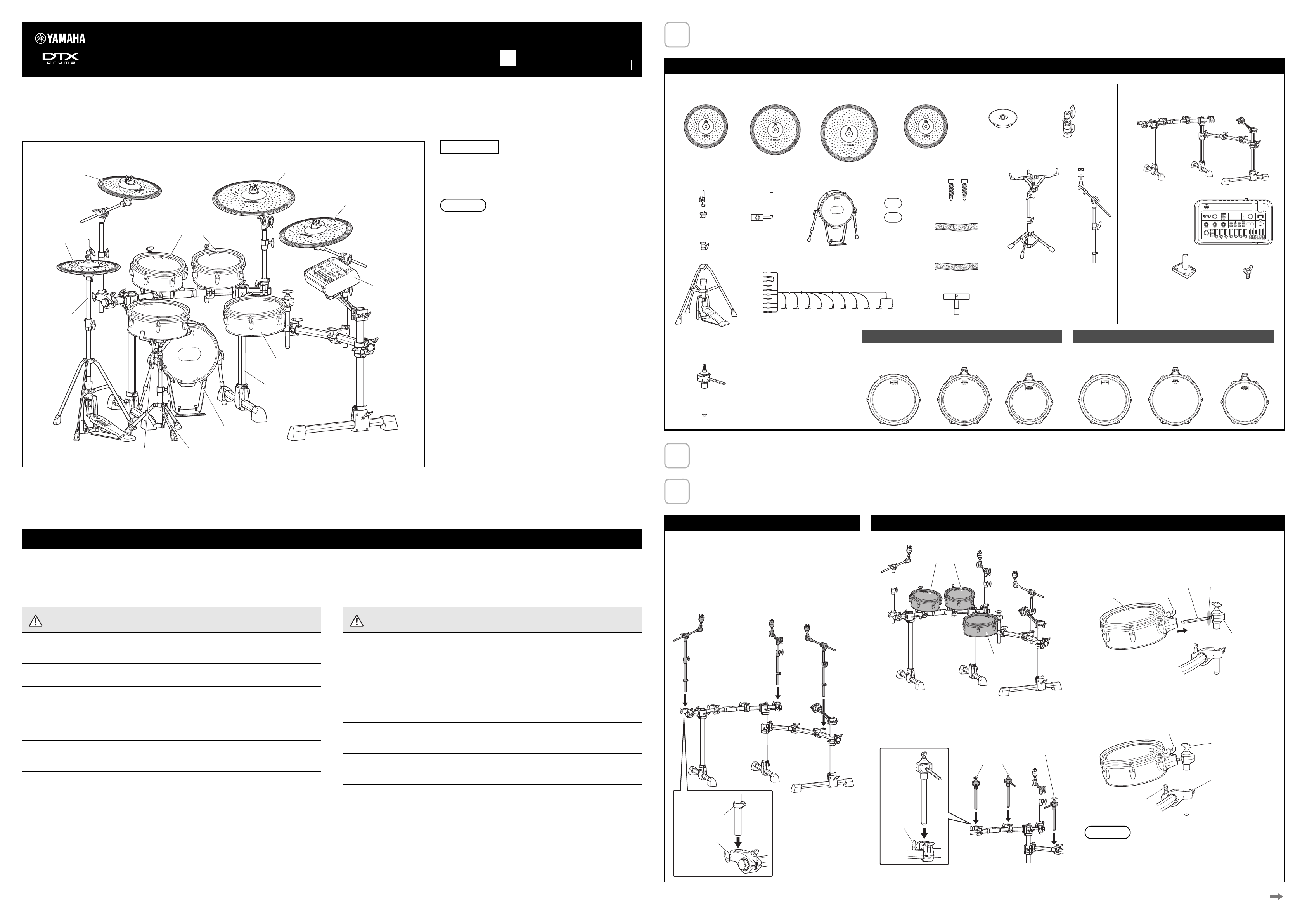
Example of standard assembly
Cymbal pad
Tom pads
Kick pad
Snare pad
Hi-hat stand
DTX-PROX Drum
trigger module
Real hi-hat pad
Cymbal pad
Tom pad
Cymbal pad
Electronic drum rack
Snare stand
The purpose of the precautions detailed below is to ensure that this electronic drum kit can be used safely without fear of injury or property damage. Precautions are extremely important in terms of ensuring
safety, and therefore, they should be fully observed.
* After reading this Assembly Manual, ensure that it is kept in a safe, convenient location for future reference.
* Be sure to also read the Assembly Manuals and/or Owner’s Manuals that came with your pads and rack.
* The illustrations as shown in this manual are for instructional purposes only, and may appear somewhat dif-
ferent from those on your product.
* The company names and product names in this manual are the trademarks or registered trademarks of their
respective companies.
* The contents of this manual apply to the latest specifications as of the publishing date. To obtain the latest
manual, access the Yamaha website then download the manual file. Since specifications, equipment or sep-
arately sold accessories may not be the same in every locale, please check with your Yamaha dealer.
NOTICE: Usage Precautions
• When connecting and disconnecting cables, be sure to hold the plug and not the cable itself. In addition,
avoid placing heavy items on top of cables and do not allow them to touch sharp edges. Failure to avoid
these precautions can lead to cable breakage and disconnection.
• Do not climb onto the electronic drum kit and avoid placing heavy objects on it. Failure to observe this pre-
caution can result in malfunction.
• Do not use or keep the product in places with extremely high temperature (places in direct sunlight, close to
a heater, in a closed car, etc.) or high humidity (bathroom, outside on a rainy day, etc.). Doing so can result
in deformation, discoloration, damage or deterioration.
• When cleaning the product, use a soft and dry/slightly damp cloth. Do not use paint thinners, solvents, alco-
hol, cleaning fluids, or chemical-impregnated wiping cloths.
PRECAUTIONS Please read carefully before proceeding
Failure to observe the precautions described below can result in
injury and/or property damage.
• Assemble this product in the proper sequence by following the assembly instructions in this man-
ual. Also, make sure to tighten the bolts regularly. Failure to do so might result in damage to the
product or even injury.
• Do not let small children assemble or set up this product by themselves, or they can be injured.
Always assemble this product with adult supervision.
• Be careful with the edges of the cymbal holders and the tom holders. The sharp holder ends can
result in injury.
• The stoppers at the tip of the legs, anti-slip stoppers on kick pads and on foot pedals have sharp
tips. In order to avoid injury, therefore, you should take special care whenever handling these com-
ponents.
• Be sure to securely tighten bolts and other fasteners when setting up this product. In addition, be
sure to proceed slowly when loosening bolts. If this precaution is not observed, pads can fall off or
the rack can collapse or fall over, possibly causing injury.
• Do not place the product in an unstable position where it might accidentally fall over.
• Whenever setting up this electronic drum kit, ensure that cables and the like are arranged safely. If
someone were to trip on a cable, the kit could topple over and cause injury.
• Do not alter the product. Doing so can result in injury or damage/deterioration to the product.
Failure to observe the precautions described below can result in
injury and/or property damage.
• Do not sit or step on the rack. The rack can overturn or be damaged, resulting in injury.
• Be careful with your fingers and hands when adjusting clamps, to prevent them from becoming
pinched and injured.
• Be careful around pipe ends and inside. Metal shavings, etc. can injure your fingers and hands.
• Do not place hands or feet under a hi-hat stand, kick pad or foot pedal. Doing so could result in
injury.
• Keep small parts out of the reach of infants. Your children may accidentally swallow them.
• Do not go near the product during an earthquake. Strong shaking during an earthquake could
cause the product to move or tip over, resulting in damage to the product or its parts, and possibly
causing injury.
• When transporting or moving the product, always use two or more people. Attempting to lift the
product by yourself may damage your back, result in other injury, or cause damage to the product
itself.
Manual Development Group
© 2020 Yamaha Corporation
Published 08/2020
POMA*.*- **A0
VDR6920
Open the boxes to reveal their contents.
After opening up the packages containing your electronic drum kit, verify that all of the following components are present.
Assemble the RS10-HXR Electronic Drum Rack.
For instructions on how to assemble the RS10-HXR Electronic Drum Rack, refer to the Owner’s Manual that came with it.
Assemble the pads and the drum trigger module to the electronic drum rack.
Components of both DTX10K-X and DTX10K-M
PCY135 Cymbal
Pad (×1)
PCY155 Cymbal
Pad (×1)
RHH135 Real
Hi-hat Pad (×1)
Stand base for
RHH135 (×1)
RS10-HXR Electronic Drum Rack (×1)
RS10-HXR Owner’s Manual (×1)
Drum key (×1)
HS740A Hi-hat
Stand (×1)
KP128 Kick Pad
(×1)
Ten-channel snake cable (×1)
Stopper for Cymbal
Pad (×3)
Cable band (×9)
Cable band for RHH135
(×1)
DTX10K-X DTX10K-M Assembly Manual
(this leaflet; ×1)
PCY100 PCY135 PCY155 PCY175
Owner’s Manual (×1)
RHH135 Owner’s Manual (×1)
KP128 Owner’s Manual (×1)
DTX-PROX Drum
Trigger Module (×1)
AC adaptor (×1)
* May not be included depending on your particular area.
Check with your Yamaha dealer.
DTX-PROX Owner’s Manual (×1)
Cubase AI Download information (×1)
Module holder
(×1)
Module holder screw
(×4)
XP125SD-X
Snare Pad (×1)
Hi-hat clutch for
RHH135 (×1)
Drum key (×1)
Anti-slip stopper for KP128
(incl. spring) (×2)
DTX10K-X only DTX10K-M only
XP125SD-M
Snare Pad (×1)
XP105T-M
Tom Pad (×2)
SS662 Snare
Stand (×1)
CH755 Cymbal
Holder (×3)
Tom Holder (×3) XP105T-X
Tom Pad (×2)
XP105T-X XP105T-M
XP125T-X XP125T-M
XP125SD-X XP125SD-M
Owner’s Manual (×1)
PCY175 Cymbal
Pad (×1)
Spare patch
for KP128
(×2)
XP125T-M
Tom Pad (×1)
XP125T-X
Tom Pad (×1)
1. Assemble the cymbal holders (CH755 × 3) on the electronic
drum rack as shown below, and then tighten the fixing bolt
to secure the holder in place.
NOTE
You can change the position of a position clamp to mark the
settings for future setups and to prevent unintentional changes
during musical performances. Make sure to secure the position
clamp using the drum key after moving the clamp.
CH755
CH755 CH755
Fixing bolt
Position clamp
Assembling the cymbal holders
1. Assemble the tom holders (×3) on the electronic drum rack as
shown above, and then tighten the fixing bolt to secure the
holder in place.
2. Push the tom pads onto the tom holder’s rods. Leave a gap
of about a half inch between the base of the tom holder and
the tom pad, and then tighten the wing bolt to secure the pad
in place.
3. Loosen wing bolts A to B and fixing bolts C to D as shown be-
low to adjust the height and angle of any of the pads. When
correctly positioned, be sure to securely retighten the bolts
before proceeding to the next step.
Before every playing, tighten the drum key bolts so that there is no
rattling and loosening of the head, in order to prevent malfunction.
Refer to the “Head tension adjustment” in the XP105T-X XP105T-
M XP125T-X XP125T-M XP125SD-X XP125SD-M Owner’s Manual.
Tom holders
Tom holder
Fixing bolt
Tom holder
Wing boltTom pad
Insert
Rod section Leave a gap
Fixing bolt C
Wing bolt A
Wing bolt B
Fixing bolt D
Continued on other side


