Yamaha RS-95 Installation guide

H
G
F
E
D
C
B
電子ドラムラックシステム RS95 組立説明書
■RS95 梱包内容 ※ ラックを組み立てる前に、すべての部品が
そろっていることを確認してください。
左サイド集成(x1) センターパイプ集成 A(x1)
右サイド集成(x1)
このたびはヤマハ電子ドラムラックシステム RS95 をお買い上げいただきまして、まことにありがとうございます。
お使いになる前に、この組立説明書をよくお読みになり、安全に正しくお使いくださいますようお願い申し上げます。
センターパイプ集成 B(x1)
モジュールホルダークランプ
(x1)
六角ロッドシリンダ(x5)
A
M
N
L
K
J
I
ドラムパッドクランプ(ショート)(x1) ドラムパッドクランプ(ロング)(x3) シンバルホルダー(x2)
ケーブルバンド(x10) チューニングキー(x1)
組立説明書(本紙)
フェルトワッシャー(x2)
*仕様および外観は改良のため予告なく変更する場合があります。
安全へのこころがけ
ご使用の前に、この『安全へのこころがけ』を
よくお読みのうえ正しくお使いください。
特にお子様には、最初にご家族の方、
または指導者から取扱い方法の指導をお願いいたします。
人身傷害の危険を防止するには
〜以下の指示を必ず守ってください〜
注意(危険・警告を含む)を促す
内容があることを告げるものです。
禁止の行為を告げるものです。
行為を強制したり指示する
内容を告げるものです。
弦打楽器事業部国内営業部ギタードラム営業課
〒430-8650浜松市中沢町10-1TEL053(460)2433
■ ヤマハ株式会社 EM 営業統括部
各地区お問い合わせ先
●北海道営業所
〒 064-8543札幌市中央区南 10 条西 1 丁目 1-50
TEL011(512)6113
●仙台営業所
〒 980-0804仙台市青葉区大町 2-2-10
TEL022(222)6147
●東京・営業推進課
〒 108-8568東京都港区高輪 2-17-11
TEL03(5488)5476
●名古屋営業所
〒 460-8588名古屋市中区錦 1-18-28
TEL052(201)5199
●大阪営業所
〒 542-0081大阪市中央区南船場 3-12-9
TEL06(6252)5231
●九州営業所
〒 812-8508福岡市博多区博多駅前 2-11-4
TEL092(472)2130
ホームページ http://www.yamaha.co.jp/
モジュールホルダー(x1)
*+−トラスコネジ 5 × 8 4 本付属
設置場所は床面が平らで丈夫な所にしてくだ
さい。床が傾いていたり、段差がありますと不
安定となり、転倒する恐れがあります。
固定用ネジはしっかり締め付けてください。
転倒、落下等によりけがの原因となります。
高さや角度の調整をおこなう際、急にネジを
緩めないでください。パッドが落下したり、
ラック、パイプが滑り落ちて手や指を挟む等
けがの原因となります。
ラックに腰かけたり踏み台にしないでくださ
い。転倒したり壊れたりして、けがの原因とな
ります。
小さなお子様が触ったり、近づく場合は注意
してください。多くのパイプやアームが並び
ますので、動きによっては体をぶつけたりし
て、けがをする恐れがあります。
パッドやモジュールのセッティングの際は、
ケーブルの引きまわしに注意してください。
足を引っかけて転倒する恐れがあります。
この表示を無視して誤った取扱いを
すると、人が死亡又は重傷を負う危
険の恐れがある内容を示しています。
警告
フットスイッチやフットペダルの下に、手や足
を入れないでください。
挟まれてけがの原因となります。
クランプを調節する際、指に注意してくださ
い。指が挟まれてけがをする恐れがあります。
パイプの端面や内面及びネジの先端にご注意く
ださい。尖った部分等で指にけがをする恐れが
あります。
電子ドラムラックには、アコースティックドラ
ムを取り付けないでください。クランプの破損
や、ドラムの落下などで、けがをする恐れがあ
ります。
この表示を無視して誤った取扱いをすると、
人が傷害を負ったり、財産が損害を受ける
危険の恐れがある内容を示しています。
注意

■RS95 +パッド類:セットアップ例
●パッド、ドラムトリガーモジュール類(別売品)
qDTXTREME
ドラムトリガーモジュール
yTP80S/TP80
ドラムパッド
uPCY80S/PCY80
シンバルパッド
iKP120
キックパッド
!0HH60
ハイハットコントロールペダル
!1 フットペダル
※ DFP-880 など
*スネア用パッドのセッティングにはスネアスタンドを使用ください。
oPCY10
トリガーパッド
!2 スネアスタンド
※ SS-642 など
tRHP80
リアルヘッドパッド
(8 インチ)
eRHP120
リアルヘッドパッド
(12 インチ)
wRHP120SD
スネア用リアルヘッドパッド
(12 インチ)
rRHP100
リアルヘッドパッド
(10 インチ)
※ RS95 に付属のドラムパッドクランプ
H
I
、六角ロッド
シリンダ
G
には RHP80 までの軽量パッドの取り付けが可
能です。
RHP100/120 などの大
型で重量のあるパッドを取
り付ける場合はタムホル
ダー TPCL100(別売)
の使用をお勧めします。
TPCL100
タムホルダー
w
!0
i
y
q
uo
!1
!2
t
A
B
C
D
J
t
J
G
I
H
G
G
I
F
E

4ドラムパッドクランプ
H
I
の取り付け
4-1 ドラムパッドクランプ
H
I
に六角ロッドシリンダ
G
を差し
込み、固定ネジを締め付けます。
4-2 ドラムパッドクランプ(ショート)
H
はフロアタムのポジ
ションに取り付けます。
ドラムパッドクランプ(ロング)
I
はハイハットとタムタム
のポジションに取り付けます。
4-3 ドラムパッドを六角ロッドシリンダ
G
に差し込み、向きを調
整し、固定します。
RHP100/120などの大型パッドを取り付ける場合はタムホ
ルダー TPCL100(別売)の使用をお勧めします。
シンバルホルダー
J
の取り付け
5-1 センターパイプ集成A
C
の左右にセットされたシンバルホル
ダー用クランプに、シンバルホルダー
J
を差し込み、固定ネ
ジを締め付けます。
5-2 シンバルパッドをシンバルホルダー
J
に取り付け、向きを調
整し、固定します。(取付け方法は、シンバルパッドの取扱説
明書をご参照ください。)また、PCY10 を使用の場合は、下
図で指示する部品を使用します。
1左サイド集成
A
のパイプと右サイド集成
B
のパイプにセンターパ
イプ集成 A
C
を差し込み、固定ネジを締めます。
サイド集成の左右を間違えないように注意してください。
3モジュールホルダー
E
の取り付け
3-1 モジュールホルダークランプ
F
に六角ロッドシリンダ
G
を
差し込み、固定ネジを締め付けます。
3-2 モジュールホルダークランプ
F
を左サイド集成
A
のパイプ
に取り付けます。
3-3 DTXTREMEをモジュールホルダー
E
に取り付けます。ドラ
イバーを使って、モジュールホルダー
E
に付属のネジで、
DTXTREME の底面のネジ穴へ固定します。
3-4 モジュールホルダークランプ
F
に、DTXTREMEを取り付け
たモジュールホルダー
E
を取り付けます。
2センターパイプ集成B
D
を差し込み、固定ネジを締めます。
■RS95 組み立て手順
※組み立てに際して、ドライバー(+またはー)をご用意ください。
組み立てが完成したら、キックパッド、ハイハットコントロールペダルな
どをセットし、結線します。各ケーブルは、演奏のじゃまにならないよう
に、ケーブルバンド
K
でパイプに固定しましょう。
手順5-2
センターパイプ集成 A
C
左サイド集成
A
右サイド集成
B
締める
シンバルホルダー
J
ドラムパッドクランプ
(ショート)
H
ドラムパッドクランプ
(ロング)
I
締める
シンバルホルダー
J
ドラムパッドクランプ
(ロング)
I
手順4-1
手順5-1
六角ロッドシリンダ
G
手順4-2
手順4-3
センターパイプ集成 B
D
DTXTREME
モジュールホルダー
E
手順3-3
締める
六角ロッドシリンダ
G
手順3-2
手順3-1
モジュールホルダークランプ
F
左サイド集成
A
シンバル
パッド
5
※*印はPCY10付属品です。
※PCY10に同梱のチルターへの交換は必要ありません。
● PCY10 使用の場合
PCY10
シンバル
パッド
フェルト(小)*
フェルト(大)*
ワッシャ*
チルター
回り止め金具
(PCY80/80Sに付属)
フェルトワッシャ
M
に交換してください。
手順3-4
クランプやパッドなど各部の固定ネジはしっかりと締め付けてください。
緩かったり締めすぎたりすると、落下や破損の原因となります。ご注意ください。

Electronic Drum Rack System
RS95
Assembly Instruction
Thank you for purchasing the Yamaha Electronic Drum Rack System RS95.
Before using, thoroughly read this assembly manual, and use this product safely and correctly.
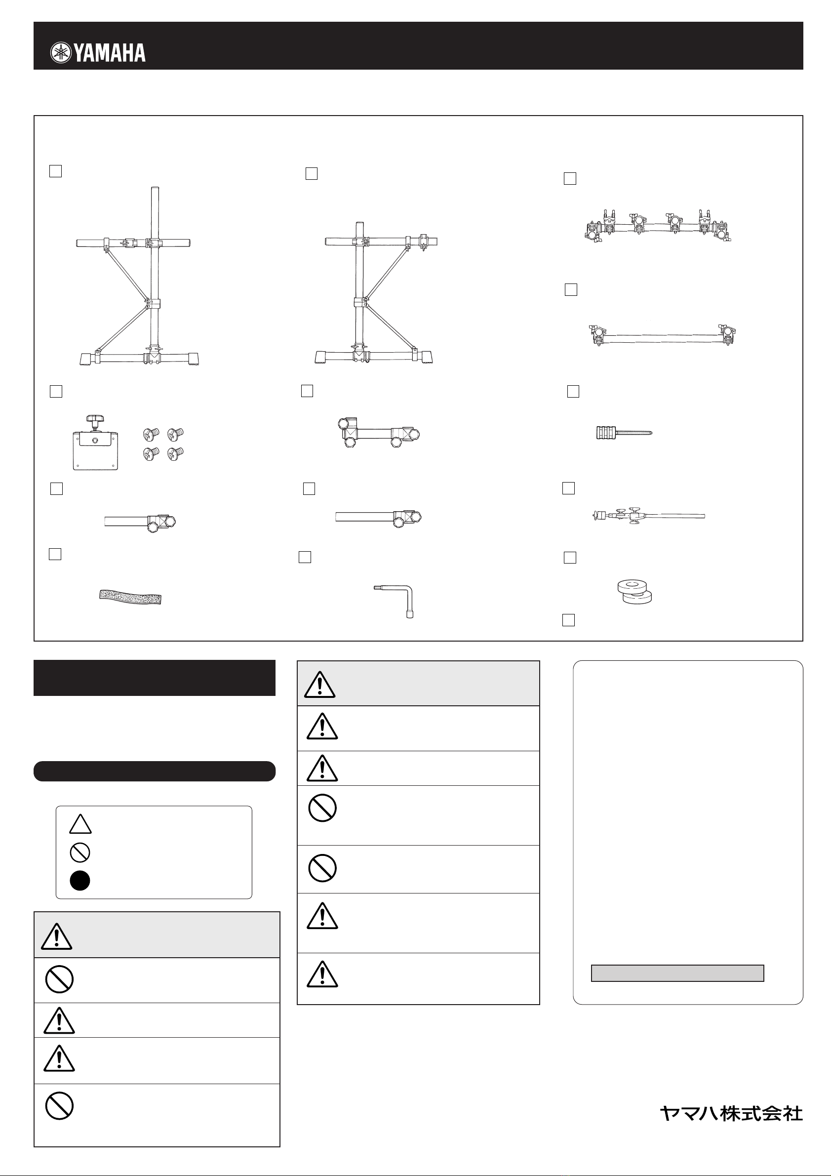
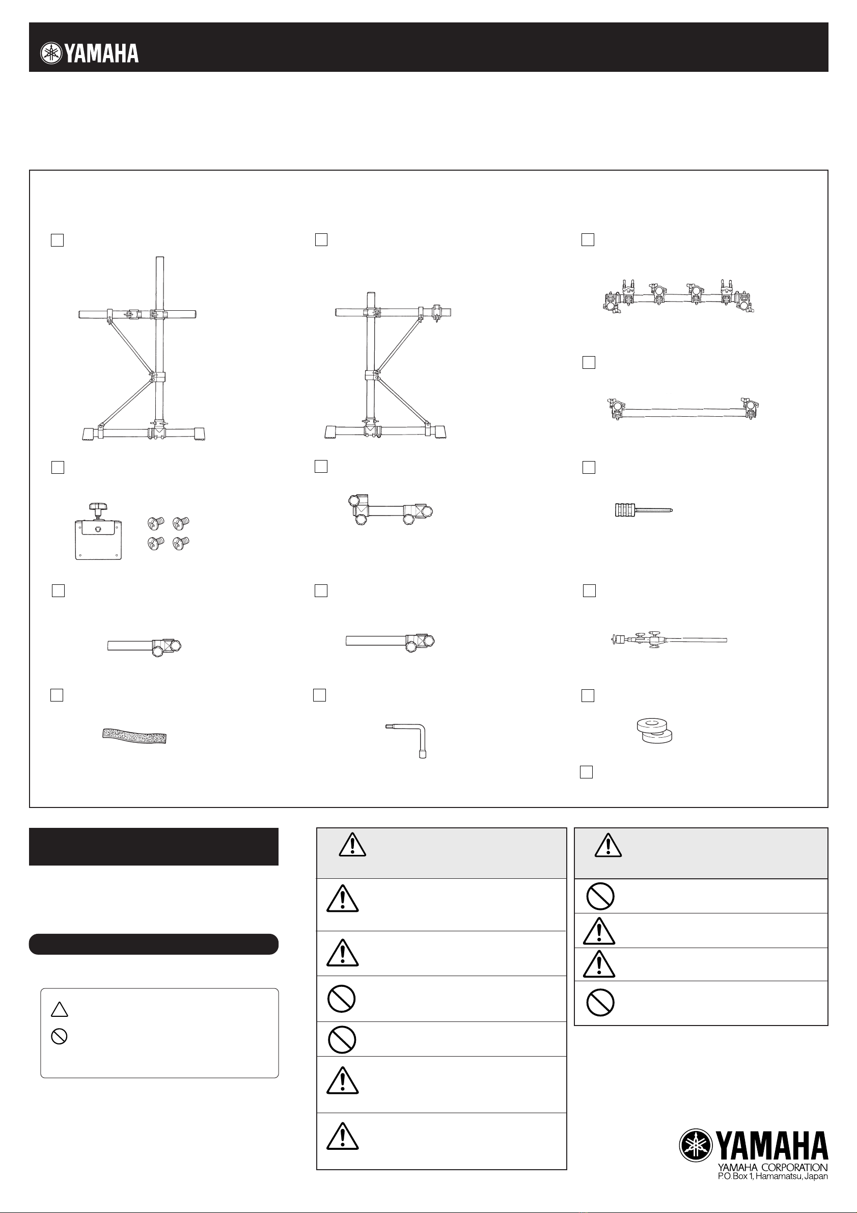
■
RS95 Rack Stand Parts
* Before assembling the rack stand, make sure all of the parts shown below are included.
PrintedinTaiwan
Left Side Assembly (x1)
H
G
F
E
D
C
B
A
M
N
L
K
J
I
Center Pipe Assembly A (x1)
Center Pipe Assembly B (x1)
Right Side Assembly (x1)
Hex Rod Cylinder (x5)Module Holder Clamp (x1)
Assembly Instruction
(this sheet)
Tuning Key (x1)
Cable Band (x10)
Cymbal Holder (x2)
Felt Washer (x2)
Drum Pad Clamp (Long) (x3)Drum Pad Clamp (Short) (x1)
* Specifications are subject to change without notice.
PRECAUTIONS
Before using, please read this “Assembly Instruction” sheet,
and use this product in a safe and proper manner.
Especially for children, parents or an instructor should teach the
children the proper manner in which to use the device.
Topreventagainstaccidentsandinjury
Pleasefollowthecautionslistedbelow
Caution (including danger, or warning). This mark indicates
cautions in which you should pay close attention to.
Acts indicated with this icon are prohibited and should not
be attempted.
This icon indicates acts that you are urged to follow.
●
Module Holder (x1)
(4 screws included)
* Specifications are subject to change without notice.
Always set the instrument on a flat and solid surface.
Placement on a sloping, unstable surface or on steps
may result in the instrument being unstable and over-
turning.
Make sure all bolts are tightened firmly. Loose bolts
may result in the rack overturning or parts dropping
causing injury.
When adjusting the height or angle, do not suddenly
loosen the bolt. The pad may drop, the rack or pipes
may slip, pinching or causing injury to hands or fingers.
Do not sit or step on the rack. The rack may overturn
or be damaged resulting in injury.
Please be careful when children are close to or touch-
ing the product. The product has many pipes and arms
so careless movement around the product may result
in injury.
When setting the pads and modules, please pay close
attention in regards to the handling and setting of
cables. Feet may become entangled in the cables re-
sulting in falls.
If this symbol is ignored and the equipment is
used improperly, fatal injury to persons or se-
rious damage could occur.
Do not put your hands or feet under the foot pedal or
foot switch. They may be pinched resulting in injury.
Watch your fingers when adjusting clamps. They may
become pinched resulting in injury.
Be careful around pipe ends, inside the pipe and screw
ends. Metal shavings, etc. may injure your fingers.
Do not attach acoustic drums to the electronic drum
rack. Clamps may be damaged and drums may drop,
causing injury.
If this symbol is ignored and the equipment is
used improperly, there is a danger of injury to
persons handling the equipment, and material
damage could occur.
CAUTION
WARNING

● Pad and Drum Trigger Grouping (option)
w
!0
i
y
q
uo
!1
!2
t
A
B
C
D
J
t
J
G
I
H
G
G
I
F
E
qDTXTREME
Drum Trigger Module
tRHP80
Real Head Pad (8inch)
rRHP100
Real Head Pad (10inch)
eRHP120
Real Head Pad (12inch)
yTP80S/TP80
Drum Pad
!2Snare Stand
*SS-642 etc.
!1Foot Pedal
*DFP-880 etc.
uPCY80S/PCY80
Cymbal Pad
oPCY10
Trigger Pad
iKP120
Real Head Kick Pad
!0HH60
Hi-hat Control Pedal
TPCL100
Tom Holder
■
RS95+Pad Grouping: Setup Example
* Please use a snare stand for setting the snare drum pad.
wRHP120SD
Snare Type Real Head Pad
(12inch)
* The supplied Drum Pad Clamp
H
I
can be attached
to the RS95 and the Hex Rod Cylinder
G
can be used
to attach lighter pads up to
the RHP80.
When a large, heavy
pad, such as the RHP100/
120 is to be attached, we
recommend the use of the
tom holder TPCL100 (op-
tional).
Includes Holder Clamp Assembly.

■
RS95 Assembly
* A screw driver (+ or -) is necessary to complete the assembly.
1
3
2
Center Pipe Assembly A
C
Tighten
Right Side Assembly
B
Center Pipe
Assembly B
D
Left Side Assembly
A
DTXTREME
Step 3-3
Step 3-2
Step 3-1
Tighten
Left Side Assembly
A
Module Holder Clamp
F
Hex Rod Cylinder
G
Module Holder
E
Step 3-4
Please make sure that the fixing bolts on each part, such as clamps, pads, etc. are firmly tightened.
Bolts that are too tight or too loose may result in damage to the part or the part dropping. Please use caution.
Attach the Center Pipe Assembly A
C
to the upright pipes of the Left
Side Assembly
A
and the Right Side Assembly
B
, and tighten the
wing bolts.
Attach the Center Pipe Assembly B
D
, and tighten the wing bolts.
Attach the Module Holder
E
3-1 Insert the Hex Rod Cylinder
G
into the Module Holder Clamp
F
, and tighten the fixing screw.
3-2 Attach the Module Holder Clamp
F
to the upright pipe on the
Left Side Assembly
A
.
3-3 Attach the DTXTREME to the Module Holder
E
. Using a screw
driver and the supplied screws, attach the Module Holder
E
to
the screw holes on the bottom of the DTXTREME.
3-4 Attach the Module Holder
E
, with the DTXTREME attached, to
the Module Holder Clamp
F
.
4
5
After the above assembly is complete, set the Kick Pad, Hi-Hat Control
pedal, etc. into position and connect the necessary cables. To keep
cable out of the way while playing, use the supplied Cable Bands
K
to
hold the cables to the rack system's pipes.
Tilter
Cymbal Pad
PCY10
Step 4-2
Step 5-2
Cymbal Pad
Felt (Small)*
Felt (Large)*
Washer*
Step 4-1
Step 5-1
Step 4-3
Cymbal Holder
J
Hex Rod Cylinder
G
Cymbal Holder
J
Drum Pad Clamp
(Short)
H
Drum Pad Clamp
(Long)
I
Drum Pad Clamp
(Long)
I
Tighten
Attach the Drum Pad Clamps
H
I
4-1 Insert the Hex Rod Cylinders
G
into the Drum Pad Clamps
H
and
I
, and tighten the fixing screws.
4-2 Attach the Drum Pad Clamp (short)
H
to the floor tom position.
Attach the Drum Pad Clamps (long)
I
to the high-hat and tom-
tom positions.
4-3 Attach the drum pad to the Hex Rod Cylinder
G
, align the pad
and secure.
When a large pad, such as the RHP100/120 is used, we recom-
mend that the tom holder TPCL100 (optional) be used.
Attach the Cymbal Holders
J
5-1 Insert the Cymbal Holders
J
into the cymbal holder clamps that
are positioned on the left and right sides of the Center Pipe
Assembly A
C
, and secure with the wing bolts.
5-2 Attach the cymbal pads to the Cymbal Holders
J
, align the
pads and secure. (Refer to the cymbal’s Owner’s Manual.) Also,
when the PCY10 is used, please use the parts shown in the
diagram below.
● When the PCY10 is used.
Anti-swivel brace
(supplied with the
PCY80/80S)
Change to the felt
washer
M
.
* The * indicates parts supplied with the PCY10.
* It is not necessary to use the tilter that is supplied with the PCY10.
Table of contents
Other Yamaha Drum manuals

Yamaha
Yamaha DTX Drums PCY175 User manual

Yamaha
Yamaha DD-11 User manual

Yamaha
Yamaha TP100 User manual

Yamaha
Yamaha BS-832/836/240 User manual

Yamaha
Yamaha DTX RS500 User manual

Yamaha
Yamaha RX 5 Quick start guide

Yamaha
Yamaha DD-11 User manual

Yamaha
Yamaha ED10 User manual

Yamaha
Yamaha RS-60A Installation guide

Yamaha
Yamaha FGDP-30 User guide

Yamaha
Yamaha XP105T-X User manual

Yamaha
Yamaha DTXPLORER Drum Trigger Module DTXPLORER User manual

Yamaha
Yamaha DD-7 User manual

Yamaha
Yamaha DTXT2S User manual

Yamaha
Yamaha FGDP-30 User manual

Yamaha
Yamaha DS550U User manual

Yamaha
Yamaha RX-15 Manual

Yamaha
Yamaha KP120 User manual

Yamaha
Yamaha DTX Drums DTX502 Mounting instructions

Yamaha
Yamaha DTX KP128 User manual