MODELS
3JH3(B)(C)E49
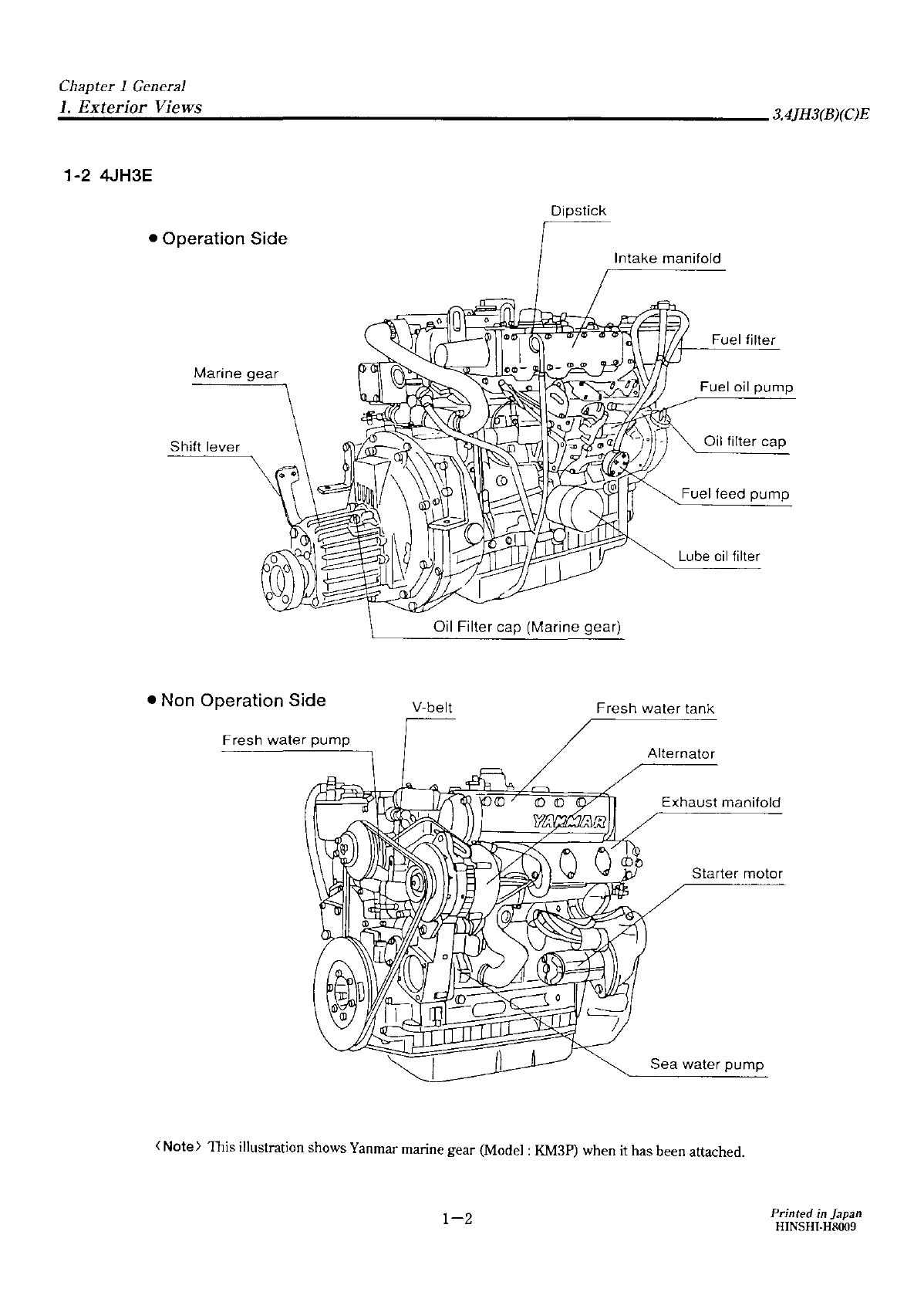
4JH3(B)(C)E
Chapter 1 GENERAL
1.
Exterior
Views···················································1-1
2.
Specifications
···················································1-3
3.
Engine Outling
················································1-6
4.
Piping Diagrams
·············································1-10
Chapter
2 INSPECTION AND SERVICING OF
BASIC ENGINE PARTS
1.
Cylinder
Block···················································2-1
2.
Cylinder
Head··················································
·2-4
3.
Piston and Piston Pins
····································2-11
4.
Connecting Rod
·············································2-15
5.
Crankshaft and Main Bearing
···························2-18
6.
Camshaft and Tappets
····································2-21
7.
Timing Gear
···················································2-24
8.
Flywheel and Housing···
....................................
2-26
Chapter 3 FUEL INJECTION EQUIPMENT
1.
Fuel injection Pump Service Data
......
·...··...··...···
·3-1
2.
Governor ··..·..·..·..····..·..····..·..··············..······..··3-4
3.
Disassembly, Reassembly and Inspection of
Fuel injection pump
..........................................
3.14
4.
Adjustment of Fuel Injection Pump and Governor ···3-24
5.
Fuel Feed Pump
.............................................
3.30
6.
Fuel injection Nozzle
············
...........................
3.32
7.
Troubleshooting ······
.......................................
3.35
8.
Tools
............................................................
3.35
9.
Fuel Filter ·
.......
········......··
........
··.....·..·······..···3-40
10.Fuel Tank
......................................................
3.41
11.Troubleshooting
····················
.........................
3.42
Chapter 4 INTAKE AND EXHAUST SYSTEM
1.
lntank System
........
·....
··········
...
······
.....·-·.....·.....
4.1
2.
Exhaust System ....··
.............
·...···...··...·······..·....4.2
Chapter 5 LUBRICATION SYSTEM
1.
Lubrication System
........
······
........
······...··...·····
·5-1
2.
Lube Oil Pump
................
·
............
·....·····
.......
··5-2
3.
Lube Oil Filter ··...·····...·..······
..........
·....··...·····...·5-6
4.
Lube Oil Cooler
..................................
··
..........
··5-8
5.
Rotary Waste Oil Pump (Optional) ··············
..........
5.9
Chapter 6 COOLING WATER SYSTEM
1.
Cooling Water System
..........
···..··
......................
5.1
2.
Sea Water Pump
.............................................
5.3
3.
Fresh Water
Pump····································
.........
5.5
4.
Heat Exchanrger ..·......·..·......··....·..··...··...·······6-8
5.
Pressure Cap and Sub Tank
..............................
5.10
6.
Thermostat ········..····..·······..·..·..··....··············6-12
7.
Bilge pump and Bilge Strainer (Optional)
............
5.14
Printed in Japan
HINSHI-H8009
Chapter 7 REDUCTION AND REVERSING GEAR
Marine Gear Models [KM3A]
1. Construction
...................................................
7.1
2.
Shifting Device ·......···············..·····......···...·······7-7
3.
Inspection and Servicing
................
······...·
.......
···7-12
4.
Disassembly
·································
...............
7.20
5.
Reassembly
...................................................
7.25
Marine Gear Models [KM3P)
1.
Construction
·······
.........................................
7.29
2. Shifting Device
................................................
7.35
3.
Inspection and Servicing·····.....
········
.....····
.......
··7-40
4.
Disassembly
................................................
7.45
5.
Reassembly ..···.....·
..............
·
..................
·······7-53
Chapter 8 REMOTE CONTROL (OPTIONAL)
1. Remote Control System
....................................
5.1
2.
Remote Control Installation
.................................
8-2
3.
Remote Control Inspection
.................................
5.4
4.
Remote Control Adjust ment .....············...·····....·8-5
Chapter9 ELECTRICAL SYSTEM
1.
Electrical System
.......
··....·
.........
·
............
··......
·9-1
2.
Battery
............................................................
9.5
3.
Starter Motor ..···.....····
...........
··....·......····....··...9.5
4.
Alternator Standard,
12V/55A
······························9-22
5. Alternator
12V/80A
(OPTIONAL)
...........................
9.30
6.
Instrument Panel
....................
···
...............
·····..9.40
7.
Warning Devices
.............................................
9.42
8.
Air Heater (Optional) ··········...·········
.................
9.45
9.
Electric type Engine Stopping Device (Optional) ······9-46
10.Tachometer
···········
........................................
9.45
Chapter
10
DISASSEMBLY AND REASSEMBLY
1.
Disassembly and Reassembly Precautions····....····10-1
2.
Disassembly and Reassembly Tools
..................
10-2
3.
Disassembly and Reassembly··..
·········
..............
10-14
4. Table of Standard Measurements for Maintenance ···10-35
5.
Tightening torque
...........
·····...······
.........
·····...10-40
6.
Test Running
................................................
10-41
Chapter
11
TROUBLESHOOTING
1.
Troubleshooting
.............................................
11-1