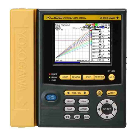
YOKOGAWA XL100 User manual

User’s
Manual
IM XL100C-E
XL100
Portable Data Station
Communication Function
IM XL100C-E
2nd Edition: May 2006 (MC)

1
IM XL100C-E
Introduction
Thank you for purchasing our XL100 Portable Data Station.
This Communication Function Manual provides information necessary for using
communication functions and creating communication programs. To ensure correct use,
please read this manual thoroughly before beginning operation.
In addition to this manual, the User’s Manual (contained in the CD-ROM as with this
manual) and Quick Setup Manual are available separately.
The User’s Manual provides detailed information regarding all of the functions and
operations of the XL100 excluding the communication functions. The Quick Setup
Manual briefly explains the basic operations such as measurement operation and setup.
Use them together with this manual.
After reading this manual, keep it in an easily accessible place for later reference. This
manual will come in handy when you are unsure of how to operate the product.
Notes
•The contents of this manual are subject to change without prior notice.
•Figures and illustrations representing display views in this manual may differ from
actual views.
•Every effort has been made to ensure accuracy in the preparation of this manual.
However, should any doubts arise or errors come to your attention, please contact the
vendor from whom you purchased the product.
•The contents of this manual may not be transcribed or reproduced, in part or in their
entirety, without prior permission.
Trademark Acknowledgements
The company and product names referred to in this document are either trademarks or
registered trademarks of their respective holders.
Revision Information
First Edition: October, 2005
Second Edition: May, 2006
2nd Edition: May 2006 (MC)
All Rights Reserved, Copyright © 2005, Yokogawa M&C Corporation

2IM XL100C-E
Safety Precautions
When operating the instrument, be sure to observe the cautionary notes given below to
ensure correct and safe use of the instrument. If you use the instrument in any way other
than as instructed in this manual, the instrument’s protective measures may be impaired.
Yokogawa Meters & Instruments Corporation is by no means liable for any damage
resulting from use of the instrument in contradiction to these cautionary notes.
The following safety symbols are used on the instrument and in this manual.
Danger! Handle with Care. This symbol indicates that the operator must refer to
an explanation in the User’s Manual or this manual in order to avoid risk of injury
or death of personnel or damage to the instrument.
This symbol indicates DC voltage/current.
This symbol indicates AC voltage/current.
This symbol indicates ON (power).
This symbol indicates OFF (power).
WARNING
Indicates a hazard that may result in the loss of life or serious injury of the user
unless the described instruction is abided by.
CAUTION
Indicates a hazard that may result in an injury to the user and/or physical damage
to the product or other equipment unless the described instruction is abided by.
Note
Indicates information that should be noted in order to familiarize yourself with the
instrument’s operating procedures and/or functions or gives supplementary information.

3
IM XL100C-E
Description of Displays and Exemption from
Responsibility
Description of Displays
•Some of the representations of product displays shown in this manual may be
exaggerated, simplified, or partially omitted for reasons of convenience when
explaining them.
•Figures and illustrations representing the controller’s displays may differ from the
actual displays in regard to the positions and/or indicated characters (upper-case or
lower-case, for example), to the extent that they do not impair correct understanding
of the functions and the proper operation and monitoring of the system.
Exemption from Responsibility
•Yokogawa Meters & Instruments does not make any warranties regarding the product
except those mentioned in the WARRANTY that is provided separately.
• Yokogawa Meters & Instruments assumes no liability to any party for any loss or
damage, direct or indirect, caused by the use of the product, or any unpredictable
defect of the product.
•Be sure to use spare parts approved by Yokogawa Meters & Instruments when
replacing parts or consumables.
•Modification of the product is strictly prohibited.
•Reverse engineering such as the disassembly or decompilation of software is strictly
prohibited.
•No portion of the product supplied by Yokogawa Meters & Instruments may be
transferred, exchanged, leased or sublet for use by any third party without the prior
permission of Yokogawa Meters & Instruments.

4IM XL100C-E
Contents
Safety Precautions ......................................................................................................................... 2
Description of Displays and Exemption from Responsibility .......................................................... 3
Chapter 1 Overview of the Communication Functions
1.1 Relationship between the Communication Function and the Ethernet and
Serial Interfaces ...............................................................................................................1-1
1.2 Explanation of Functions .................................................................................................. 1-2
Chapter 2 Ethernet Interface
2.1 Ethernet Interface Specifications ..................................................................................... 2-1
2.2 Connecting of the Ethernet Interface ............................................................................... 2-2
2.3 Configuring of the Ethernet Interface ............................................................................... 2-3
2.4 Checking the Connection Status of the Ethernet Interface .............................................. 2-7
2.5 Setting the FTP Client (Setting the Auto Transfer of Measurement and
Alarm Data Files) ............................................................................................................. 2-8
2.6 FTP Test ........................................................................................................................ 2-11
2.7 Setting the Login of Ethernet Communications .............................................................. 2-13
2.8 Showing the Error, Communication, and FTP Log Displays .......................................... 2-16
2.9 Setting the Web Server Function ................................................................................... 2-19
2.10 Showing and Using the Monitor or Operator Page ........................................................ 2-22
2.11 Setting the E-mail Transmission Function ..................................................................... 2-24
2.12 E-mail Transmission Test .............................................................................................. 2-29
2.13 Starting/Stopping E-mail Transmissions ........................................................................ 2-31
Chapter 3 Serial Interface
3.1 RS-232 Interface Specifications and Setup Procedure .................................................... 3-1
3.2 RS-485 Interface Specifications and Setup Procedure .................................................... 3-5
3.3 USB Communication Specifications and Setup Procedure ............................................. 3-8
Chapter 4 Modbus Protocol
4.1 Modbus Protocol Specifications and Function Codes ...................................................... 4-1
4.2 Register Assignments (for Modbus Slave) ....................................................................... 4-2
4.3 Modbus Error Response (for Modbus Slave) ................................................................... 4-3
4.4 Setting the Modbus Master Function ............................................................................... 4-4
4.5 Data Dropout Handling of the Modbus Master ................................................................. 4-7
Chapter 5 Standard Protocol
5.1 Command Syntax ............................................................................................................ 5-1
5.2 Response Syntax ............................................................................................................. 5-3
5.3 A List of Commands ....................................................................................................... 5-19
5.4 Input Range Parameters ................................................................................................ 5-23
5.5 Setting Commands (Setting) .......................................................................................... 5-25
5.6 Setting Commands (Control) ......................................................................................... 5-30
5.7 Basic Setting Commands ............................................................................................... 5-32
5.8 Output Commands (Control) .......................................................................................... 5-42
5.9 Output Commands (Setting/Measurement/Data Output) ............................................... 5-43
5.10 Output Commands (RS-485 Dedicated Commands) ..................................................... 5-45
5.11 Maintenance/Test Commands (Available when using the maintenance/test
server function via Ethernet communications) ............................................................... 5-46

5
IM XL100C-E
1
1
2
3
4
5
6
7
App
App
Index
Index
Chapter 6 Status
6.1 Status Information andFilter ............................................................................................. 6-1
6.2 Bit Structure of the Status Information ............................................................................. 6-2
Chapter 7 Error Messages
7.1 Error Messages Related to Settings ................................................................................ 7-1
7.2 Error Messages Related to Operation ............................................................................. 7-3
7.3 Communication Error Messages ...................................................................................... 7-8
Appendix
Appendix 1 ASCII Character Codes ....................................................................................App-1
Appendix 2 Login Process ...................................................................................................App-2
Appendix 3 Data Output Flow .............................................................................................. App-4
Appendix 4 Time Zones and XG Command Parameters .................................................... App-6
Index
Contents

1-1
IM XL100C-E
1
1
2
3
4
5
6
7
App
Index
Overview of the Communication Functions
1.1 Relationship between the Communication
Function and the Ethernet and Serial Interfaces
The XL100 comes standard with an Ethernet interface for connecting a LAN cable and a
serial interface (RS-232/RS-485 and USB). To use the communication function of the
XL100, the Ethernet or serial communication settings must be configured in advance.
The following figure shows the relationship between the communication function of the
XL100 and the Ethernet and serial interfaces.
Application
10BASE-T/100BASE-TX
IP
Serial
communication
control
MODBUS
slave
FTP
server
Maintenance/
Test server
Setting/Measurement
server
XL100 communication function
MODBUS
master
Serial
Lower layer
protocol
Upper layer protocol
Upper interface
Lower interface
Web
server
FTP client E-mail client
USB
MODBUS protocol
Standard protocol HTTP FTP SMTP
TCP
Ethernet
Login
(User authentication/
access privileges granting)
RS-232/RS-485
To use the communication function of the XL100 via the Ethernet or serial interface,
communications must be performed according to the following protocols* that lie in
between two.
•FTP (File Transfer Protocol)
•TCP (Transmission Control Protocol)
•IP (Internet Protocol)
•HTTP (Hyper Text Transfer Protocol)
•SMTP (Simple Mail Transfer Protocol)
•XL100 standard protocol (dedicated protocol)
To use the serial communication function, select one of the following protocols.
•XL100 standard protocol (dedicated protocol)
•Modbus protocol (slave)
• Modbus protocol (master)
Chapter 1 Overview of the Communication Functions

1-2 IM XL100C-E
1.2 Explanation of Functions
This section gives an overview of the communication function that can be used to control
the XL100.
Modbus Communication
Modbus Slave
• The Modbus protocol can be used to read the measured/calculated data written to the
input register of the XL100 from a PC or write/read communication input data from the
hold register of the XL100.
•For details on the Modbus function codes that the XL100 supports, see section 4.1.
•This function can be used only when communicating via the serial interface.
•For a description on the settings required to use this function, see sections 4.2 and
4.3.
Modbus Master
• Loads the measured data and other types of data of other instruments using the
Modbus protocol as communication channel input. The loaded data can be scaled
and displayed with a unit that you assign. The data can also be handled on a
calculation channel.
•Function for writing data to other instruments is not supported.
•For details on the Modbus function codes that the XL100 supports, see section 4.1.
•This function can be used only when communicating via the serial interface.
•For a description on the settings required in using this function, see section 4.4.
Setting/Measurement Server
• This function can be used to set almost all of the settings that can be configured using
the front panel keys. This function cannot be used to (1) turn the power switch ON/
OFF, (2) set the user name/password for communications, (3) set the user name/
password for key login, and (4) set the destination of the FTP client function.
•The following types of data can be output.
•Measured/calculated data.
•Data in the internal memory or files in the external storage medium.
•Setup data.
•Log data of operation errors and communications.
•The commands that can be used through this function are setting commands and
output commands.
•This function can be used when communicating via the Ethernet or the serial
interface.
Maintenance/Test Server
•This function can be used to output connection information, network information, and
other information regarding Ethernet communications.
•The commands that can be used through this function are maintenance/test
commands.
•This function can be used only when communicating via the Ethernet interface.

1-3
IM XL100C-E
1
1
2
3
4
5
6
7
App
Index
Overview of the Communication Functions
FTP Server
• You can use a PC to access the XL100 via FTP. You can perform operations such as
retrieving directory and file lists from the internal memory or the external storage
medium of the XL100 and transferring and deleting files.
•This function can be used only when communicating via the Ethernet interface.
Note
Do not use this function while logging. Logging may be aborted due to file access.
PC
Ethernet
Hub
Hub
Load measured data
PC
Load measured data
FTP server
FTP Client
•Automatic File Transfer
•The display data file and log data file that are created in the internal memory or
external storage medium of the XL100 can be automatically transferred to a remote
FTP server. The result of the transfer is recorded in the FTP log. The FTP log can
be shown on the XL100’s display or output to a PC using commands.
Ethernet
Primary
FTP server
Hub
Hub
Automatically save
measured data
Secondary
FTP server
FTP client
You can specify two destination FTP servers, primary and secondary. If the primary
server is down, the file is transferred to the secondary server.
•This function can be used only when communicating via the Ethernet interface.
•FTP Test
•The file transfer can be checked by transferring a test file from the XL100 to a
remote FTP server.
• The result of the FTP test can be confirmed on the FTP log display.
•This function can be used only when communicating via the Ethernet interface.
1.2 Explanation of Functions

1-4 IM XL100C-E
Login
•This function can be used only when communicating via the Ethernet interface and
when using the setting/measurement server, maintenance/test server, and the FTP
server functions.
•User Authentication
This function allows only registered users to access the XL100 in order to prevent
third party access from the network.
•Up to seven names can be registered. One of the names is fixed to administrator
privilege. For the other six names, you specify the access privilege when you
register the name.
•There are limitations on the number of simultaneous connections and the number
of simultaneous users accessing the XL100 from PCs (see section 2.1).
•Login to the FTP server is allowed only by an administrator or through anonymous
login (see section 2.7).
•Granting Access Privileges
This function grants access privilege (user level) to operate the XL100 for the
registered users. For example, this prevents user B (user level) from changing the
measurement conditions that were set by user A (administrator level).
• There are two user levels on the XL100, user and administrator.
• Administrator
An administrator has privileges to use all setting/measurement server functions,
maintenance/test server functions, and FTP server functions.
•User
A user has limited privileges to use the setting/measurement server functions,
maintenance/test server functions, and FTP server*1functions.
•Limitations on the use of the setting/measurement server
A user cannot change settings that would change the XL100 operation. A
user can output measured data and setting data.
• Limitations on the use of the maintenance/test server
A user cannot disconnect a connection between another PC and the XL100.
A user can disconnect the connection between the PC that the user is using
and the XL100.
•Limitations on the use of the FTP server
You cannot save files to the external storage medium of the XL100 or delete
files on it. You can load files.
*1User level access to the FTP server is allowed only by an anonymous user (see
section 2.7).
•Communication Timeout
This function drops the connection with the PC if there is no data transfer for a given
time at the application level. For example, this function prevents a PC from being
connected to the XL100 indefinitely which would prohibit other users from making new
connections for data transfer.
Web Server
•This function can be used only when communicating via the Ethernet interface.
•The XL100 display can be shown on a Web browser (for Web browsers that have
been tested for compatibility, see section 2.10).
•The following two pages are available.
•Monitor page: Monitoring screen (switching is possible among measurement
data displays, alarm summary display, and log displays)
1.2 Explanation of Functions

1-5
IM XL100C-E
1
1
2
3
4
5
6
7
App
Index
Overview of the Communication Functions
•Operator page: This page allows you to switch the XL100 display. You can also
switch to Setting mode or File Operation mode to control the
XL100 in the respective mode.
You can use access control (user name and password) to limit the access to each
page.
•The display section of the XL100 can be updated periodically (select from 2, 5, 10, or
30 s).
•The following information can be displayed.
•Measured data
•Alarm summary
•Logs (error log, communication command log, key login/logout log, FTP client log,
e-mail log, and Web operation log)
E-mail Transmission
This function can be used only when communicating via the Ethernet interface.
•Transmitting E-mail Messages
• E-mail can be automatically transmitted at the times indicated below. You can
specify two groups of destinations and specify the destination for each item. In
addition, you can set a header string for each item.
•When an alarm is activated/released
Notifies alarm information.
•When the XL100 recovers from a power failure
Notifies the power failure occurrence.
• When an error related to the external storage medium and FTP client occurs
Notifies the error code and message when an error is detected on the external
storage medium or when the data cannot be stored due to insufficient free
space on the external storage medium. In addition, notifies the error code and
message when data transfer fails using the FTP client function.
•At the specified time
Transmits an e-mail message when the specified time is reached. This can be
used to confirm that the e-mail transmission function including the network is
working properly. You can specify the reference time and the e-mail transmission
interval for each destination.
•E-mail Transmission Test
•You can send a test message from the XL100 to the destination to check e-mail
transmissions.
•You can confirm the result of the e-mail transmission test on the e-mail log screen.
Other Functions
•SNTP (Simple Network Time Protocol) Connection
You can synchronize the standard clock by connecting to an SNTP server when using
the Ethernet interface. This function works at power-on and at specified time intervals
only when the XL100 is in Free Running Mode.
•Checking the Connection Status of the Ethernet Interface
You can check the connection status of the Ethernet interface with the LAN port LED
on the side panel of the XL100 and on the display of the XL100.
•Keepalive (Extension Function of TCP)
This function drops the connection if there is no response to the test packet that is
sent periodically at the TCP level.
1.2 Explanation of Functions

1-6 IM XL100C-E
•Displaying the Error, Communication, FTP, Web Operation, and E-mail Logs
You can display the following operation logs on the log display.
•Error log display: Log of operation errors.
• Communication command display: Log of communication input/output.
• FTP client log display: Log of file transfers carried out using the FTP client function.
•Web operation log display: Log of operations using the Web server function.
•E-mail log display: Log of e-mail transmissions.
1.2 Explanation of Functions

2-1
IM XL100C-E
Ethernet Interface
1
2
3
4
5
6
7
App
Index
2.1 Ethernet Interface Specifications
Basic Specifications
Item Specifications
Number of ports 1
Electrical and mechanical specifications Conforms to IEEE 802.3.
Transmission medium type Ethernet (100BASE-TX/10BASE-T)
Data rate 100 Mbps maximum
Protocol TCP/IP
Supported services FTP server, FTP client, SMTP client (mail
transmission), Web server, DHCP, DNS, and SNTP
Connector type RJ-45
Maximum Number of Simultaneous Connections/Number of Simultaneous Users
The following table shows the maximum number of simultaneous connections, the
number of simultaneous users, and the port number for each function.
Function Maximum Number Number of Simultaneous Users Port Number*1
of Connections Administrator User
Setting/Measurement server 3 1 2*2 34339
Maintenance/Test server 1 1 1*2 34340
FTP server 2 2 2*2 21
*1 The port numbers are fixed.
*2 There are user limitations. For details, see “Granting Access Privileges” under “Login” in section 1.2.
Chapter 2 Ethernet Interface

2-2 IM XL100C-E
2.2 Connecting of the Ethernet Interface
When Connecting Only the XL100 and the PC
Connect the LAN ports of the XL100 and the PC using a 10BASE-T or 100BASE-TX
LAN cable.
LOGIC/PULSE
ALARM
RS232
LAN port
LAN cable
If you are connecting the XL100 and the PC directly in a one-to-one configuration without
using a hub, use a cross LAN cable.
When Connecting to an Existing Network
When connecting the XL100 or the PC to an existing network, communication
parameters such as the data rate and connector type must be matched. For details,
consult your system or network administrator.
Note
•Depending on the reliability of the network or the volume of network traffic, all the
transferred data may not be retrieved by the PC.
•Communication performance deteriorates if multiple PCs access a XL100
simultaneously.
•If the interface is not set to LAN, do not connect the LAN cable.

2-3
IM XL100C-E
Ethernet Interface
1
2
3
4
5
6
7
App
Index
2.3 Configuring of the Ethernet Interface
The following configurations must be made to use the Ethernet communication functions
of the XL100.
Selecting the Communication Interface
Communication can only be performed on a single interface at any given time. You must
select the communication interface by carrying out the steps below. The default setting is
LAN (Ethernet).
Procedure
1. Press SETTING to enter Setting Mode.
2. Use the arrow keys to select COMMUNICATION, and press SELECT.
→
3. With INTERFACE selected, press SELECT.
An interface selection list is displayed.
4. Use the arrow keys to select a communication interface, and press SELECT.
5. Press SET.
Setting the Ethernet Parameters
•Setting the Time Zone
Set the time difference from Greenwich Mean Time.
•Setting the DHCP, IP Address, Subnet Mask, Default Gateway, and DNS
Consult your system or network administrator when setting parameters such as the IP
address, subnet mask, default gateway, and DNS (domain name system).
•DHCP (Dynamic Host Configuration Protocol)
•The IP address, subnet mask, default gateway, and DNS can be automatically
set by using DHCP.
•To use DHCP, the network must have a DHCP server.
•Consult your network administrator to see if DHCP can be used.
•If you use DHCP, a different IP address may be assigned each time the XL100
is powered up. You must pay attention when using the FTP server function of
the XL100.

2-4 IM XL100C-E
•IP Address
• Set the IP address to assign to the XL100. The default setting is 0.0.0.0.
•The IP address is used to distinguish between the various devices connected to
the Internet when communicating using the TCP/IP protocol. The address is a
32-bit value expressed using four octets (each 0 to 255), each separated by a
period as in [192.168.111.24].
•Subnet Mask
•Specify the mask that is used to determine the network address from the IP
address. The default setting is 0.0.0.0.
•Set the value according to the system or network to which the XL100 belongs. In
some cases, this setting may not be necessary.
• Default Gateway
•Set the IP address of the gateway (router, etc.) used to communicate with other
networks. The default setting is 0.0.0.0.
•Set the value according to the system or network to which the XL100 belongs. In
some cases, this setting may not be necessary.
•DNS (Domain Name System)
You must set the DNS if you are using a host name to specify the destination
server of the file transfer on an FTP client or the server of the e-mail recipient.
*DNS is a system used to associate names used on the Internet called host
names and domain names to IP addresses. The host name/domain name can
be used instead of the IP address when accessing the network. The DNS server
manages the database that contains the host name/domain name and IP
address correlation.
•DNS Server
•Set the IP address of the DNS server. The default setting is 0.0.0.0.
• You can specify up to two DNS server IP addresses, primary and secondary.
If the primary DNS server is down, the secondary DNS server is automatically
looked up for the mapping of the host name/domain name and IP address.
•Host Name
Set the XL100’s host name using up to 64 characters.
• Domain Name
• Set the network domain name that the XL100 belongs to using up to 64
characters.
•When the destination server of the file transfer or the server of the e-mail
recipient is looked up using the DNS server, this domain name is appended
to the host name as a possible domain name if it is omitted. The recipient
name (server name) is set to the name specified by FTP Server Name or
SMTP Server Name.
•Domain Suffix
When the IP address corresponding to the server name with the domain name
of the previous section is not found, the system may be set up to search using a
different domain name. In such cases, set the domain name to be searched
following the “domain name” of the previous section as a domain suffix.
• Set the domain suffix using up to 64 characters.
•You can specify up to two domain suffixes, primary and secondary.
2.3 Configuring of the Ethernet Interface

2-5
IM XL100C-E
Ethernet Interface
1
2
3
4
5
6
7
App
Index
•Setting the SNTP (Time Synchronization Function)
You can synchronize the standard clock by connecting to an SNTP server at power-
on and at specified timer intervals when the XL100 is in Free Running Mode using the
Ethernet interface. The following items are set in addition to the Ethernet interface to
use this function.
•SNTP ON/OFF
Select whether to enable (ON) or disable (OFF) SNTP.
•Server Name
Set the host name or IP address using up to 64 alphanumeric characters.
•Confirmation Time
Set the cycle for synchronizing the clock in the range of 1 to 24 hours.
•Enabling/Disabling the Login Function of the XL100
The item below applies when the XL100 is used as a setting/measurement server or
maintenance/test server on the Ethernet interface. It does not apply to login when
using the XL100 as an FTP server (see section 2.7).
If you enable the login function, only registered users can log in to the XL100.
•Communication Timeout
The item below applies when the XL100 is used as a setting/measurement server or
maintenance/test server on the Ethernet interface. When using the XL100 as an FTP
server, the connection is dropped when there is no data exchange for 5 minutes
regardless of this setting.
•Selecting ON or OFF
•ON
Drops the connection when there is no data exchange for a given time.
•OFF
Communication timeout is disabled.
•Setting the Timeout Value
If communication timeout is enabled, the connection is dropped if no data transfer
is detected over a time period specified here.
Selectable range: 1 to 120 minutes
•Enabling/Disabling (On/Off) Keepalive
•ON
If there is no response to the inspection packet that is periodically transmitted
(every 30 s) at the TCP level, the connection is forcibly disconnected.
•OFF
Keepalive is disabled.
•Saving the Settings
To activate the settings that have been changed in the basic setting mode, the
settings must be saved. Otherwise, the settings that existed before the change are
activated.
Procedure
1. Press SETTING to enter Setting Mode.
2.3 Configuring of the Ethernet Interface

2-6 IM XL100C-E
2. Use the arrow keys to select COMMUNICATION, and press SELECT.
→
3. Use the arrow keys to select ETHERNET, and press SELECT.
→
4. Use the arrow keys to select the desired item, and press SELECT.
Press SELECT to show a selection list or display for setting the item.
•IP Address Setting display
•DNS Setting display
•SNTP Setting display
5. Select or enter the item on the displayed selection list or window.
6. Press SET.
2.3 Configuring of the Ethernet Interface

2-7
IM XL100C-E
Ethernet Interface
1
2
3
4
5
6
7
App
Index
2.4 Checking the Connection Status of the
Ethernet Interface
Checking the Connection Status on the XL100
You can check the connection status of the Ethernet interface with the LAN port LED of
the XL100.
LED Status Connection Status of the Ethernet Interface
Green LED illuminated The Ethernet interface is electrically connected.
Yellow LED blinking Transmitting data.
Off The Ethernet interface is not electrically connected.
LAN
Green LED
Blinks when data
transmission is normal.
Illuminates when communication is
possible with the connected destination.
Yellow LED
Checking the Connection Status on the XL100 Display
You can check the connection status with the icon that is shown in the status display
section of the XL100 display. The icon appears when the interface is set to LAN, the
Ethernet parameters (IP address other than 0.0.0.0) are configured, and the cable is
connected. For other cases, the icon is gray.

2-8 IM XL100C-E
2.5 Setting the FTP Client (Setting the Auto Transfer
of Measurement and Alarm Data Files)
By setting this function, the measurement and alarm data files created in the internal
memory of the XL100 or an external storage medium can be automatically transferred
using FTP at the time the files are created. To use this function, however, the Ethernet
interface must be configured as described in section 2.3.
•Selecting the Transferred Files
•You can select whether to automatically transfer the measurement and alarm data
files. The default setting is OFF.
•The data files are automatically transferred to the FTP destination explained in the
next section at the end of the logging operation.
Note
If a file with the same name is detected at the destination, the file is transferred with the
last character of the file name changed.
Example: If the file to be transferred named “050714130440.DLO” exists at the
destination, the file name is changed to “050714130440Fxxxx.DLO” (where
xxxx is a value between 0000 and 9999) before it is transferred.
•Setting the FTP Destination
Consult your system or network administrator when setting parameters such as the
primary/secondary FTP servers, port number, login name, password, account, and
availability of the PASV mode.
•Specifying Primary and Secondary
You can specify two destination FTP servers, primary and secondary. If the primary
server is down, the file is transferred to the secondary server.
•FTP Server Name
Enter the name of the file transfer destination FTP server using up to 64
alphanumeric characters.
•If the DNS is used, you can set the host name as a server name.
For details on setting the DNS, see section 2.3, “Setting the Ethernet Interface.”
•You can also set the IP address. In this case, the DNS is not required.
•Port Number
Enter the port number of the file transfer destination FTP server in the range of 1 to
65535. The initial value is 21.
•Login Name
Enter the login name for accessing the FTP server using up to 32 alphanumeric
characters.
•Password
Enter the password for accessing the FTP server using up to 32 alphanumeric
characters.
•PASV Mode
Turn PASV mode ON when using the XL100 behind a firewall that requires the
passive mode. The default setting is OFF. A firewall is furnished on a router (or a
similar device) that has security features. It prevents intrusion from the outside into
the network system.
Other manuals for XL100
2
This manual suits for next models
1
Table of contents
Other YOKOGAWA Data Logger manuals

YOKOGAWA
YOKOGAWA SMARTDAC+ GX10 User manual

YOKOGAWA
YOKOGAWA SMARTDAC+ GM10 Use and care manual

YOKOGAWA
YOKOGAWA MX100 User manual

YOKOGAWA
YOKOGAWA SL1000 User manual

YOKOGAWA
YOKOGAWA MW100 User manual

YOKOGAWA
YOKOGAWA Datum Y XL100 User manual

YOKOGAWA
YOKOGAWA SMARTDAC+ GX10 User manual

YOKOGAWA
YOKOGAWA SMARTDAC+ GM Manual

YOKOGAWA
YOKOGAWA XL100 User manual

YOKOGAWA
YOKOGAWA XL100 User manual