manuals.online logo
Brands
  1. Home
  2. •
  3. Brands
  4. •
  5. YOKOGAWA
  6. •
  7. Measuring Instrument
  8. •
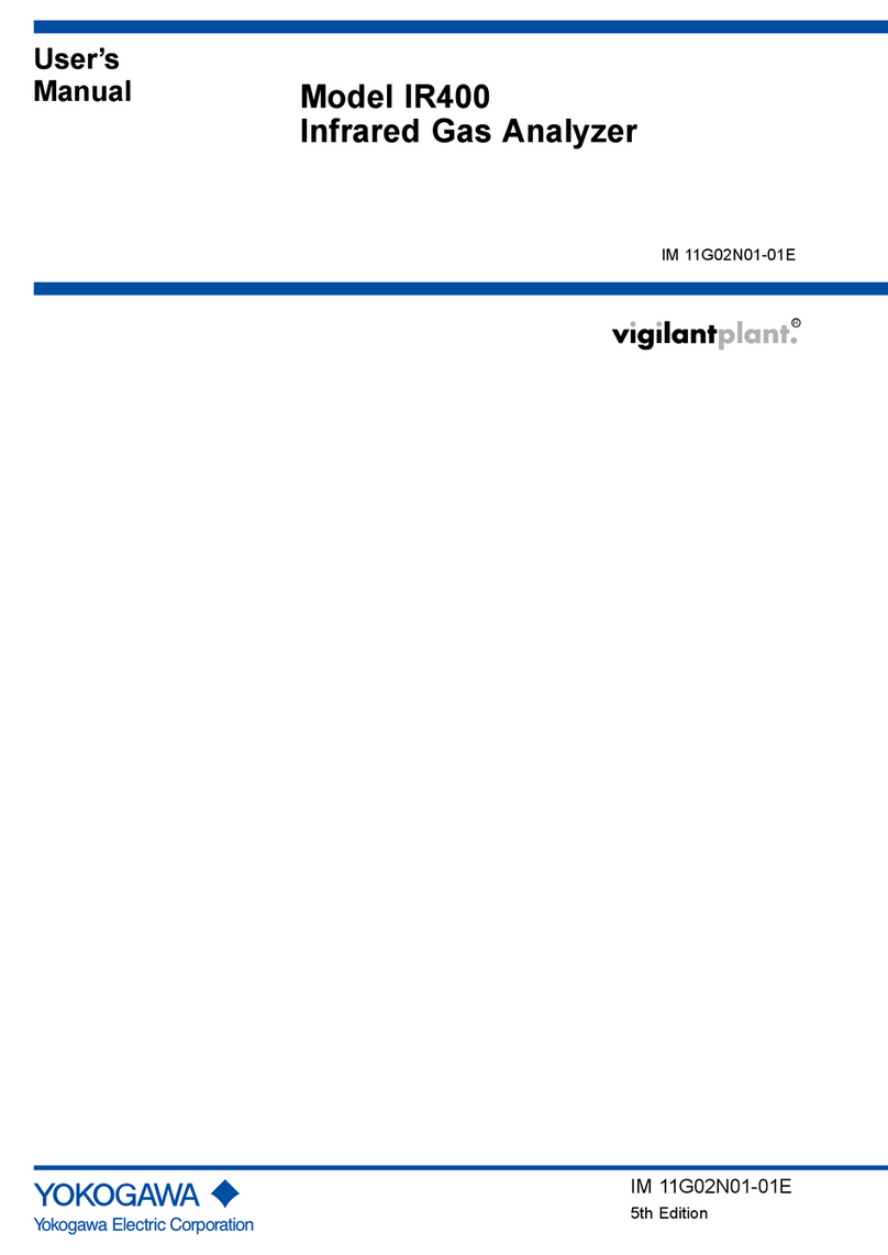
  9. YOKOGAWA UM330 User manual

YOKOGAWA UM330 User manual

User’s
Manual
This supplement is for the 1st edition of "Models UM350/UM330 Digital Indicator with
Alarms"(IM05F01D02-41E).
This supplement provides with an error correction.
Models UM350/UM330
Digital Indicator with Alarms
User’s Manual
Supplement
IM 05F01D02-01E-S01
2000.8
IM 05F01D02-01E-S01
■ Model UM350 Digital Indicator with Alarms -Terminal Wiring-
Power supply
Relay contact output
Contact rating: 250 V AC, 3 A
30 V DC, 3 A (resistance load)
* Wiring can only be carried out
for indicators with communication
functions.
Maximum baud rate: 9600 bps
Allowable range: 100 to 240 V AC (⫾10%)
(free voltage)
50/60 Hz shared
Installation category (overvoltage category): II (IEC1010-1)
NOTE
Initial Settings User’s Manual
PV input
* Not configured at factory before shipment
See ,
for more information.
*Wiring can only be carried out
for indicators with 24 V DC
loop power supply.
16
17
Retransmission output
4-20 mA DC
16
17
15 V DC loop power supply
14.5-18.0VDC
(21 mA DC max.)
* PV retransmission is configured at factory
before shipment.
Load resistance: 600
Ω or less
*If 15 V DC loop power supply is used,
retransmission output cannot be used.
-
+
-
+
CAUTION
Before carrying out wiring, turn off the power to the
indicator and check that cables to be connected are
not alive with a tester or the like because there is
a possibility of electric shock.
21
22
23
24
25
26
27
11
12
13
16
17
19
20
1
2
3
4
5
6
7
8
9
10
8
9
10
L
N
12
13
11
12
13
12
13
21
22
21.6-28.0VDC
(30 mA DC max.)
23
24
25
26
27
SDB(+)
SDA(-)
RDB(+)
RDA(-)
SG
6
5
4
7
AL1
AL2
AL3
COM
Relay contact rating: 240 V AC, 1 A
30 V DC, 1 A (resistance load)
1
2
3
Alarm 4 output
NC
NO
COM
A
b
B
UM
+
-
* Wiring can only be carried out for
UM350-ⵧ1 or UM350-ⵧ2.
-
+
-
+
TC input
RTD input
mV/V input
12
13
+
-
Note: Connecting a 250 Ωresistor to the terminals is
optional.
Model: X010-250-2 (resistor with M3.5 crimp-on
terminal lugs)
* When receiving 4-20 mA DC current signals,
set the PV input type to 1-5 V DC (setpoint 41 ).
䊏
Receiving 4-20 mA DC Current
Signals with the Indicator
250 Ω4-20mA
19
20
DI1
COM
Resets the PV
peak and bottom values
when DI1 is changed
from OFF to ON
.
Common
UM
Contact input
Contact
Contact rating: 12 V DC, 10 mA or more
DI1
COM
+5V
Transistor contact
19
20
RS-485 communication
Alarm output
Relay
Alarm 1 output
Alarm 2 output
Alarm 3 output
Common
Power supply
24 V DC loop
power supply
Correction
2
IM 05F01D02-01E-S01
■ Model UM330 Digital Indicator with Alarms -Terminal Wiring-
12
13
+
-
Note: Connecting a 250 Ωresistor to the terminals is
optional.
Model: X010-250-2 (resistor with M3.5 crimp-on
terminal lugs)
* When receiving 4-20 mA DC current signals,
set the PV input type to 1-5 V DC (setpoint 41 ).
䊏
Receiving 4-20 mA DC Current
Signals with the Indicator
250 Ω4-20mA
Installation category (overvoltage category): II (IEC1010-1)
NOTE
12
13
11
12
13
12
13
A
b
B
-
+
-
+
TC input
RTD input
mV/V input
6
5
4
7
AL1
AL2
AL3
COM
UM
16
17
Retransmission output
4-20 mA DC
16
17
15 V DC loop power supply
14.5-18.0VDC
(21 mA DC max.)
* PV retransmission is configured at factory
before shipment.
Load resistance: 600
Ω or less
*If 15 V DC loop power supply is used,
retransmission output cannot be used.
-
+
-
+
11
21
13
23
3
25
5
19
9
1
17
27
7
12
22 24
4
16
26
6
20
10
28
8
9
Power supply
10
L
N
Power supply
23
24
RS-485 communication
* Wiring can only be carried out
for indicators with communication
functions.
Maximum baud rate: 9600 bps
25
26
27
SDB(+)
SDA(-)
RDB(+)
RDA(-)
SG
19
20
DI1
COM
Resets the PV
peak and bottom values
when DI1 is changed
from OFF to ON
.
Common
1
2
Relay contact output
3
Alarm 4 output
NC
NO
COM
Contact rating: 250 V AC, 3 A
30 V DC, 3 A (resistance load)
* Wiring can only be carried out for
UM330-ⵧ1 or UM330-ⵧ2.
CAUTION
Before carrying out wiring, turn off the power
to the indicator and check that cables to be
connected are not alive with a tester or the like
because there is a possibility of electric shock.
UM
Contact input
Contact
Contact rating: 12 V DC, 10 mA or more
DI1
COM
+5V
Transistor contact
19
20
*Wiring can only be carried out
for indicators with 24 V DC
loop power supply.
21
22
21.6-28.0VDC
(30 mA DC max.)
+
-
24 V DC loop
power supply
Alarm output
Relay
Alarm 1 output
Alarm 2 output
Alarm 3 output
Common
Relay contact rating: 240 V AC, 1 A
30 V DC, 1 A (resistance load)
Allowable range: 100 to 240 V AC (⫾10%)
(free voltage)
50/60 Hz shared
Initial Settings User’s Manual
PV input
* Not configured at factory before shipment
See ,
for more information.
Correction
Other manuals for UM330

1

This manual suits for next models

1

Other YOKOGAWA Measuring Instrument manuals

YOKOGAWA Power Series Plus User manual

YOKOGAWA

YOKOGAWA Power Series Plus User manual

YOKOGAWA ScopeCorder DL750 User manual

YOKOGAWA

YOKOGAWA ScopeCorder DL750 User manual

YOKOGAWA ZR802S User manual

YOKOGAWA

YOKOGAWA ZR802S User manual

YOKOGAWA DTSXL User manual

YOKOGAWA

YOKOGAWA DTSXL User manual

YOKOGAWA VigilantPlant mR20000 User manual

YOKOGAWA

YOKOGAWA VigilantPlant mR20000 User manual

YOKOGAWA AXF series User manual

YOKOGAWA

YOKOGAWA AXF series User manual

YOKOGAWA AQ7277B User manual

YOKOGAWA

YOKOGAWA AQ7277B User manual

YOKOGAWA FX1000 User manual

YOKOGAWA

YOKOGAWA FX1000 User manual

YOKOGAWA WE7281 User manual

YOKOGAWA

YOKOGAWA WE7281 User manual

YOKOGAWA ST401G User manual

YOKOGAWA

YOKOGAWA ST401G User manual

YOKOGAWA Power Series Plus User manual

YOKOGAWA

YOKOGAWA Power Series Plus User manual

YOKOGAWA AQ6370D User manual

YOKOGAWA

YOKOGAWA AQ6370D User manual

YOKOGAWA 701928 User manual

YOKOGAWA

YOKOGAWA 701928 User manual

YOKOGAWA 701939 User manual

YOKOGAWA

YOKOGAWA 701939 User manual

YOKOGAWA AQ6370D User manual

YOKOGAWA

YOKOGAWA AQ6370D User manual

YOKOGAWA SC25V-AGP25-120 User manual

YOKOGAWA

YOKOGAWA SC25V-AGP25-120 User manual

YOKOGAWA Power Series Plus IM 2493WVP-1 User manual

YOKOGAWA

YOKOGAWA Power Series Plus IM 2493WVP-1 User manual

YOKOGAWA AQ1000 OTDR User manual

YOKOGAWA

YOKOGAWA AQ1000 OTDR User manual

YOKOGAWA PH450 Instruction Manual

YOKOGAWA

YOKOGAWA PH450 Instruction Manual

YOKOGAWA CW140 User manual

YOKOGAWA

YOKOGAWA CW140 User manual

YOKOGAWA MV100 User manual

YOKOGAWA

YOKOGAWA MV100 User manual

YOKOGAWA MT10 User manual

YOKOGAWA

YOKOGAWA MT10 User manual

YOKOGAWA YPP6830 User manual

YOKOGAWA

YOKOGAWA YPP6830 User manual

YOKOGAWA VY Series User manual

YOKOGAWA

YOKOGAWA VY Series User manual

Popular Measuring Instrument manuals by other brands

Tietzsch ZAP 350L User instructions

Tietzsch

Tietzsch ZAP 350L User instructions

MGI MegaBOLT Advanced user's manual

MGI

MGI MegaBOLT Advanced user's manual

ionSign Neutron12-3G quick guide

ionSign

ionSign Neutron12-3G quick guide

Instantel Minimate Blaster Operator's manual

Instantel

Instantel Minimate Blaster Operator's manual

Hach BODTrak II user manual

Hach

Hach BODTrak II user manual

Vzor Mark-903 Operation manual

Vzor

Vzor Mark-903 Operation manual

Ferrida LDM 50M user manual

Ferrida

Ferrida LDM 50M user manual

Wohler CD 210 operating manual

Wohler

Wohler CD 210 operating manual

Met One Instruments GT-526 manual

Met One Instruments

Met One Instruments GT-526 manual

emitor EasySplicer OTDR owner's manual

emitor

emitor EasySplicer OTDR owner's manual

FTS SDI-RADAR-300WL operating manual

FTS

FTS SDI-RADAR-300WL operating manual

PTW DIAMENTOR E2 user manual

PTW

PTW DIAMENTOR E2 user manual

Flybox Omnia57 G-METER Installation and user manual

Flybox

Flybox Omnia57 G-METER Installation and user manual

Kathrein MSK 140/OHD Instructions for use

Kathrein

Kathrein MSK 140/OHD Instructions for use

SPECTRO SPECTROLAB Original operating instructions

SPECTRO

SPECTRO SPECTROLAB Original operating instructions

Drok VAH9030H manual

Drok

Drok VAH9030H manual

Alentec & Orion 24720 user manual

Alentec & Orion

Alentec & Orion 24720 user manual

Gantner Q Series manual

Gantner

Gantner Q Series manual

manuals.online logo
manuals.online logoBrands
  • About & Mission
  • Contact us
  • Privacy Policy
  • Terms and Conditions

Copyright 2025 Manuals.Online. All Rights Reserved.