YOKOGAWA DLM4038 User manual

IM DLM4038-17EN
8th Edition
Communication Interface
DLM4000 Series
Mixed Signal Oscilloscope

i
IM DLM4038-17EN
Thank you for purchasing the DLM4000 Series Mixed Signal Oscilloscope. This Communication
Interface User’s Manual explains the following interface features and commands.
• USB interface
• Ethernet interface
• GP-IB interface (option)
To ensure correct use, please read this manual thoroughly before operation.
Keep this manual in a safe place for quick reference in the event that a question arises.
List of Manuals
The following manuals, including this one, are provided as manuals for the DLM4000 series. Please
read all manuals.
Manual Title Manual No. Description
DLM4000 Series
Mixed Signal Oscilloscope
Features Guide
IM DLM4038-01EN The manual explains all the DLM4000 features
other than the communication interface features.
(included in the accompanying manual CD)
DLM4000 Series
Mixed Signal Oscilloscope
User’s Manual
IM DLM4038-02EN The manual explains how to operate the DLM4000.
(included in the accompanying manual CD)
DLM4000 Series
Mixed Signal Oscilloscope
Getting Started Guide
IM DLM4038-03EN Provided as a printed manual. This guide explains
the handling precautions, basic operations, and
specifications of the DLM4000.
(included in the accompanying manual CD)
DLM4000 Series
Mixed Signal Oscilloscope
Communication Interface User’s Manual
IM DLM4038-17EN This manual. The manual explains the DLM4000
communication interface features and instructions
on how to use them.
(included in the accompanying manual CD)
Model DLM4038, DLM4058 Mixed
Signal Oscilloscope Userʼs Manual
IM DLM4038-92Z1 Document for China
The “EN” and “Z1” in the manual numbers are the language codes.
Contact information of Yokogawa offices worldwide is provided on the following sheet.
Document No. Description
PIM 113-01Z2 List of worldwide contacts
Notes
• The contents of this manual are subject to change without prior notice as a result of continuing
improvements to the instrument’s performance and functionality. The figures given in this manual
may differ from those that actually appear on your screen.
• Every effort has been made in the preparation of this manual to ensure the accuracy of its
contents. However, should you have any questions or find any errors, please contact your
nearest YOKOGAWA dealer.
• Copying or reproducing all or any part of the contents of this manual without the permission of
YOKOGAWA is strictly prohibited.
• The TCP/IP software of this product and the documents concerning it have been developed/
created by YOKOGAWA based on the BSD Networking Software, Release 1 that has been
licensed from the Regents of the University of California.
8th Edition: July 2018 (YMI)
All Rights Reserved, Copyright © 2012 Yokogawa Test & Measurement Corporation

ii IM DLM4038-17EN
Trademarks
• Microsoft, Internet Explorer, MS-DOS, Windows, Windows 7, Windows 8, Windows 8.1, and
Windows 10 are either registered trademarks or trademarks of Microsoft Corporation in the
United States and/or other countries.
• Adobe and Acrobat are either registered trademarks or trademarks of Adobe Systems
Incorporated.
• DLM is a registered trademark of Yokogawa Electric Corporation.
• In this manual, the ® and TM symbols do not accompany their respective registered trademark
or trademark names.
• Other company and product names are registered trademarks or trademarks of their respective
holders.
About the USB Interface and Ethernet Interface
• To use the USB communication features, your PC must have the following:
• DLM Series Library (TMCTL)
• USB device driver for connecting the DLM4000 series to the PC
• To use the Ethernet communication features, your PC must have the following:
• DLM Series Library (TMCTL)
To download the libraries and drivers listed above, go to the following website, and then browse
to the download page.
http://tmi.yokogawa.com/service-support/downloads/
Sample Programs
To download sample programs, go to the following website, and then browse to the download page.
http://tmi.yokogawa.com/service-support/downloads/
Revisions
• 1st Edition: November 2012
• 2nd Edition: June 2013
• 3rd Edition: February 2015
• 4th Edition: May 2015
• 5th Edition: January 2016
• 6th Edition: October 2016
• 7th Edition: October 2017
• 8th Edition: July 2018

iii
IM DLM4038-17EN
How to Use This Manual
Structure of the Manual
This manual contains six chapters and an appendix.
Chapter 1 USB Interface
Describes the features and specifications of the USB interface.
Chapter 2 Ethernet Interface
Describes the features and specifications of the Ethernet interface.
Chapter 3 GP-IB Interface (Option)
Describes the features and specifications of the GP-IB interface.
Chapter 4 Programming Overview
Describes command syntax and other programming information.
Chapter 5 Commands
Describes every command individually.
Chapter 6 Status Reports
Describes the status byte, various registers, and queues.
Appendix
Provides reference material such as an ASCII character code table.
Index

iv IM DLM4038-17EN
Conventions Used in This Manual
Notes and Cautions
The notes and cautions in this manual are categorized using the following symbols.
WARNING Calls attention to actions or conditions that could cause serious or fatal injury to
the user, and precautions that can be taken to prevent such occurrences.
CAUTION Calls attention to actions or conditions that could cause light injury to the user or
damage to the instrument or user’s data, and precautions that can be taken to
prevent such occurrences.
French
AVERTISSEMENT Attire l’attention sur des gestes ou des conditions susceptibles
de provoquer des blessures graves (voire mortelles), et sur les
précautions de sécurité pouvant prévenir de tels accidents.
ATTENTION Attire l’attention sur des gestes ou des conditions susceptibles de
provoquer des blessures légères ou d’endommager l’instrument ou les
données de l’utilisateur, et sur les précautions de sécurité susceptibles
de prévenir de tels accidents.
Note Calls attention to information that is important for proper operation of the
instrument.
Character Notations
Hard Key Names and Soft Key Names in Bold Characters
Indicate panel keys that are used in the procedure and soft keys and menu items that appear on the screen.
SHIFT+Panel Key
When SHIFT+panel key appears in a procedural explanation, it means to press the shift key so that its
indicator lights, and then to press the indicated panel key. A setup menu for the item written in purple above
the key that you pressed appears on the screen.
Unit
k Denotes 1000. Example: 100 kS/s (sample rate)
K Denotes 1024. Example: 720 KB (file size)
Metasyntax
The following table contains the symbols that are used in the syntax discussed mainly in chapters 4
and 5. These symbols are referred to as BNF (Backus-Naur Form) symbols. For details on how to
write data using these symbols, see pages 4-6 and 4-7.
Symbol Description Example Example
<> A defined value CHANnel<x> <x> = 1 to 4 CHANNEL2
{}
|
Select an option in { }
Exclusive OR
COUPling {AC|DC|DC50|GND} COUPLING AC
[] Can be omitted CURSor [:TY]:TYPE CURSor:TYPE
How to Use This Manual

v
IM DLM4038-17EN
1
2
3
4
5
6
App
Index
Contents
List of Manuals...................................................................................................................................i
How to Use This Manual.................................................................................................................. iii
Chapter 1 USB Interface
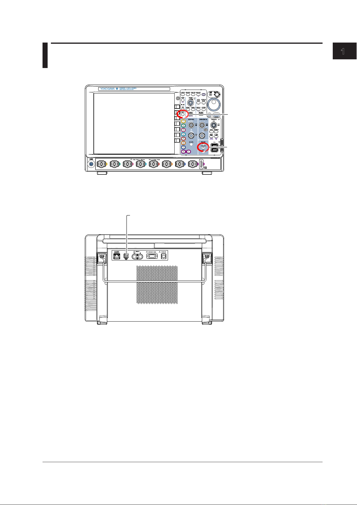
1.1 Component Names and Functions................................................................................... 1-1
1.2 USB Interface Features and Specications...................................................................... 1-2
1.3 USB Interface Connection................................................................................................ 1-4
1.4 Conguring the DLM4000 USB Settings .......................................................................... 1-5
Chapter 2 Ethernet Interface
2.1 Component Names and Functions................................................................................... 2-1
2.2 Ethernet Interface Features and Specications ............................................................... 2-2
2.3 Ethernet Interface Connection.......................................................................................... 2-4
2.4 Conguring the DLM4000 Network Settings .................................................................... 2-5
Chapter 3 GP-IB Interface (Option)
3.1 Component Names and Functions................................................................................... 3-1
3.2 Connecting GP-IB Cables ................................................................................................ 3-2
3.3 GP-IB Interface Features ................................................................................................. 3-3
3.4 GP-IB Interface Specications ......................................................................................... 3-4
3.5 Conguring the DLM4000 GP-IB Settings........................................................................ 3-5
3.6 Responses to Interface Messages ................................................................................... 3-6
Chapter 4 Programming Overview
4.1 Messages ......................................................................................................................... 4-1
4.2 Commands ....................................................................................................................... 4-3
4.3 Responses ....................................................................................................................... 4-5
4.4 Data.................................................................................................................................. 4-6
4.5 Synchronization with the Controller.................................................................................. 4-8
Chapter 5 Commands
5.1 List of Commands ............................................................................................................ 5-1
5.2 ACQuire Group............................................................................................................... 5-61
5.3 ANALysis Group ............................................................................................................. 5-62
5.4 ASETup Group ............................................................................................................... 5-79
5.5 CALibrate Group ............................................................................................................ 5-80
5.6 CHANnel Group ............................................................................................................. 5-81
5.7 CHUTil Group ................................................................................................................. 5-84
5.8 CLEar Group .................................................................................................................. 5-85
5.9 COMMunicate Group ..................................................................................................... 5-86
5.10 CURSor Group ............................................................................................................... 5-88
5.11 DISPlay Group ............................................................................................................... 5-95
5.12 FFT Group...................................................................................................................... 5-97
5.13 FILE Group................................................................................................................... 5-104
5.14 GONogo Group ............................................................................................................ 5-108
5.15 HCOPy Group ...............................................................................................................5-114
5.16 HISTory Group...............................................................................................................5-116
5.17 IMAGe Group ............................................................................................................... 5-122
5.18 INITialize Group............................................................................................................ 5-123

vi IM DLM4038-17EN
Contents
5.19 LOGic Group ................................................................................................................ 5-124
5.20 MATH Group................................................................................................................. 5-133
5.21 MEASure Group ........................................................................................................... 5-138
5.22 RECall Group ............................................................................................................... 5-148
5.23 REFerence Group ........................................................................................................ 5-149
5.24 SEARch Group............................................................................................................. 5-150
5.25 SERialbus Group.......................................................................................................... 5-156
5.26 SNAP Group................................................................................................................. 5-236
5.27 SSTart Group................................................................................................................ 5-237
5.28 STARt Group ................................................................................................................ 5-238
5.29 STATus Group .............................................................................................................. 5-239
5.30 STOP Group................................................................................................................. 5-240
5.31 STORe Group............................................................................................................... 5-241
5.32 SYSTem Group ............................................................................................................ 5-242
5.33 TIMebase Group .......................................................................................................... 5-245
5.34 TRIGger Group............................................................................................................. 5-246
5.35 WAVeform Group.......................................................................................................... 5-310
5.36 WPARameter Group..................................................................................................... 5-313
5.37 XY Group...................................................................................................................... 5-317
5.38 ZOOM Group................................................................................................................ 5-320
5.39 Common Command Group .......................................................................................... 5-322
Chapter 6 Status Reports
6.1 About Status Reports ....................................................................................................... 6-1
6.2 Status Byte ....................................................................................................................... 6-3
6.3 Standard Event Register .................................................................................................. 6-4
6.4 Extended Event Register.................................................................................................. 6-5
6.5 Output and Error Queues ................................................................................................. 6-6
Appendix
Appendix 1 ASCII Character Codes......................................................................................App-1
Appendix 2 Error Messages..................................................................................................App-2
Appendix 3 About the IEEE 488.2-1992 Standard................................................................App-5
Index

1-1
IM DLM4038-17EN
USB Interface
1
2
3
4
5
6
App
Index
1.1 Component Names and Functions
Front Panel
UTILITY key
Press this key to select the USB interface.
CLEAR TRACE
key (
SHIFT + CLEAR TRACE)
Press this key to switch to local mode. In
local mode, remote mode (remote control
using communication commands) is
cleared, and key operation becomes
possible.
However, key operation is invalid when
Local Lockout (see page 1-3) is enabled by
the controller.
Rear Panel
USB port
This port is for connecting the DLM4000 to a
controller (such as a PC) using a USB cable.
Chapter 1 USB Interface

1-2 IM DLM4038-17EN
1.2 USB Interface Features and Specifications
USB Interface Features
Reception Features
Allow you to specify the same settings that you can using the front panel keys.
Receive output requests for measured and computed data, panel setting data, and error codes.
Transmission Features
The DLM4000 can (1) transmit measured and computed data, (2) transmit panel setting data and
the status byte, and (3) error codes when errors occur.
USB Interface Specifications
Electrical and mechanical specifications: USB 2.0
Connector: Type B connector (receptacle)
Ports: 1
Power supply: Self powered
PC system requirements: A PC running the English or Japanese version of Windows 7 (32bit,
64bit), Windows 8 (32bit, 64bit), Windows 8.1 (32bit, 64bit), or Windows
10 (32bit, 64bit) and a separate device driver
Data Transfer Rate
The following table contains approximations of how much time it takes for the DLM4000 to transmit
waveform data.
Model: DLM4038
Controller: PC (Intel (R) Core (TM) i5 CPU 650 @ 3.20 GHz 3.33 GHz), USB2.0
(ICH7), OS (Windows 7) Enterprise 32 bit)
Programming language: Visual C++
Number of Data Points Byte Data Word Data ASCII Data
1250 Approx. 23 ms Approx. 23 ms Approx. 0.080 s
12500 Approx. 32 ms Approx. 24 ms Approx. 0.630 s
125000 Approx. 119 ms Approx. 42 ms Approx. 6.061 s
1250000 Approx. 998 ms Approx. 215 ms Approx. 64.833 s
12500000 Approx. 9672 ms Approx. 1932 ms Approx. 647.706 s
125000000 Approx. 95870 ms Approx. 18636 ms Approx. 6492.005 s

1-3
IM DLM4038-17EN
USB Interface
1
2
3
4
5
6
App
Index
Switching between Remote and Local Modes
Switching from Local to Remote Mode
The DLM4000 switches to Remote mode when it is in Local mode and it receives a
:COMMunicate:REMote ON command from the PC.
• “REMOTE” appears at the top center of the screen once the DLM4000 is in Remote mode.
• All keys except SHIFT+CLEAR TRACE key are disabled.
• The Local mode settings are retained even when the DLM4000 switches to Remote mode.
Switching from Remote to Local Mode
When the DLM4000 is in Remote mode and you press SHIFT+CLEAR TRACE key, the DLM4000
switches to Local mode. However, this does not work if the DLM4000 has received a
:COMMunicate:LOCKout ON command from the PC. The DLM4000 switches to Local mode when
it receives a :COMMunicate:REMote OFF command from the PC, regardless of the local lockout
state.
• The “REMOTE” indicator at the top center of the screen disappears once the DLM4000 is in
Local mode.
• All keys are enabled.
• The Remote mode settings are retained even when the DLM4000 switches to Local mode.
Note
You cannot use the USB interface at the same time as other interfaces (GP-IB and Ethernet interfaces).
1.2 USB Interface Features and Specifications

1-4 IM DLM4038-17EN
1.3 USB Interface Connection
Notes about Connections
• Be sure to insert the USB cable connector firmly into the USB port.
• If you are connecting multiple devices by using a USB hub, connect the DLM4000 to the USB
hub port that is closest to the port that the controller is connected to.
• Do not connect a USB cable to the GO/NO-GO output terminal. Doing so may damage the
DLM4000.

1-5
IM DLM4038-17EN
USB Interface
1
2
3
4
5
6
App
Index
1.4 Configuring the DLM4000 USB Settings
This section explains the settings listed below. You must configure these settings when controlling
the DLM4000 remotely through a USB interface.
• Communication interface
Opening the Remote Control Menu
Press UTILITY, and then press the Remote Control soft key to open the menu shown below.
Set the mode to USB TMC
Set the communication interface to USB
Note
• Only use the selected communication interface. If you send commands simultaneously from another
communication interface that has not been selected, the DLM4000 will not execute the commands
properly.
• To remotely control the DLM4000 through a USB port using communication commands, set USB
Function, shown in the figure above, to USB TMC, and then carry out the following steps.
- To activate the USB Function settings, you need to restart the DLM4000. Turn off the DLM4000 power
switch, wait ten seconds or more, and then turn on the switch.
- Install the YOKOGAWA USB driver (YKMUSB) on your PC. For information about how to obtain the
YOKOGAWA USB driver (YKMUSB), contact your nearest YOKOGAWA dealer. You can also access
the YOKOGAWA USB driver download webpage and download the driver.
http://tmi.yokogawa.com/service-support/downloads/
• Do not use USB drivers (or software) supplied by other companies.

2-1
IM DLM4038-17EN
Ethernet Interface
Chapter 2 Ethernet Interface
1
2
3
4
5
6
App
Index
2.1 Component Names and Functions
Front Panel
UTILITY key
Press this key to select the USB interface.
CLEAR TRACE
key (
SHIFT + CLEAR TRACE)
Press this key to switch to local mode. In
local mode, remote mode (remote control
using communication commands) is
cleared, and key operation becomes
possible.
However, key operation is invalid when
Local Lockout (see page 2-3) is enabled by
the controller.
Rear Panel
Ethernet port
This port is for connecting the DLM4000 to a
controller (such as a PC) using an Ethernet cable.

2-2 IM DLM4038-17EN
2.2 Ethernet Interface Features and Specifications
Ethernet Interface Features
Reception Features
Allow you to specify the same settings that you can using the front panel keys.
Receive output requests for measured and computed data, panel setting data, and error codes.
Transmission Features
The DLM4000 can transmit measured and computed data.
The DLM4000 can transmit panel setting data and the status byte.
The DLM4000 can transmit error codes when errors occur.
Ethernet Interface Specifications
Electrical and mechanical specifications: IEEE802.3
Simultaneous connections: 1
Protocol: VXI-11
PC system requirements: A PC running the English or Japanese version of Windows 7 (32bit, 64bit),
Windows 8 (32bit, 64bit), Windows 8.1 (32bit, 64bit), or Windows 10 (32bit,
64bit)
Data Transfer Rate
The following table contains approximations of how much time it takes for the DLM4000 to transmit
waveform data.
Model: DLM4038
Controller: PC (Intel (R) Core (TM) i5 CPU 650 @ 3.2 GHz 3.33 GHz), Ether (Intel (R)
82578DM Gigabit Network Connection), OS (Windows 7 Enterprise 32 bit)
Programming language: Visual C++
Number of Data Points Byte Data Word Data ASCII Data
1250 Approx. 25 ms Approx. 24 ms Approx. 0.090 s
12500 Approx. 25 ms Approx. 27 ms Approx. 0.630 s
125000 Approx. 128 ms Approx. 55 ms Approx. 6.100 s
1250000 Approx. 1044 ms Approx. 292 ms Approx. 65.162 s
12500000 Approx. 10207 ms Approx. 2705 ms Approx. 651.968 s
125000000 Approx. 101255 ms Approx. 26314 ms Approx. 6528.039 s

2-3
IM DLM4038-17EN
Ethernet Interface
2.2 Ethernet Interface Features and Specifications
1
2
3
4
5
6
App
Index
Switching between Remote and Local Modes
Switching from Local to Remote Mode
The DLM4000 switches to Remote mode when it is in Local mode and it receives a
:COMMunicate:REMote ON command from the PC.
• “REMOTE” appears at the top center of the screen once the DLM4000 is in Remote mode.
• All keys except SHIFT+CLEAR TRACE key are disabled.
• The Local mode settings are retained even when the DLM4000 switches to Remote mode.
Switching from Remote to Local Mode
When the DLM4000 is in Remote mode and you press SHIFT+CLEAR TRACE key, the DLM4000
switches to Local mode. However, this does not work if the DLM4000 has received a
:COMMunicate:LOCKout ON command from the PC. The DLM4000 switches to Local mode
when it receives a :COMMunicate:REMote OFF command from the PC, regardless of the local
lockout state.
• The “REMOTE” indicator at the top center of the screen disappears once the DLM4000 is in
Local mode.
• All keys are enabled.
• The Remote mode settings are retained even when the DLM4000 switches to Local mode.
Note
You cannot use the Ethernet interface at the same time as other interfaces (GP-IB and USB interfaces).
Setting the Timeout Value
If the DLM4000 is not accessed for a specified amount of time (set as a timeout value), the
DLM4000 closes the connection to the network. You can set the timeout value in the range of 0
to 600 s. The default value is 0 s. For instructions on how to set the timer value, see section 2.4,
“Network Configuration on the DLM4000.”

2-4 IM DLM4038-17EN
2.3 Ethernet Interface Connection
Connection Procedure
Connect a UTP (Unshielded Twisted-Pair) or STP (Shielded Twisted-Pair) cable that is connected to
a hub or other network device to the Ethernet port on the DLM4000 rear panel.
* Straight UTP or STP cable
Network card
Ethernet
PC
Hub or router that
supports 1000BASE-T
*
*
DLM4000
Notes about Connections
• To connect the DLM4000 to a PC, be sure to use straight cables and to connect through a hub or
router. Proper operation is not guaranteed for a one-to-one connection using a cross cable.
• Use a network cable that conforms to the transfer speed of your network.
Note
For details on how to connect the DLM4000 to a network, see section 18.1, “Connecting the DLM4000 to a
Network” in the DLM4000 Series User’s Manual (IM DLM4038-02EN).

2-5
IM DLM4038-17EN
Ethernet Interface
1
2
3
4
5
6
App
Index
2.4 Configuring the DLM4000 Network Settings
This section explains the settings listed below. You must configure these settings when controlling
the DLM4000 remotely through a ethernet interface.
• Communication interface
• Connecting to the network (Mode)
• Timeout of the network
Opening the Remote Control Menu
Press UTILITY, and then press the Remote Control soft key to open the menu shown below.
Set the communication interface to Network(VXI-11)
Set the timeout
Set the Mode to ON
Note
Only use the selected communication interface. If you send commands simultaneously from another
communication interface that has not been selected, the DLM4000 will not execute the commands properly.
Configuring TCP/IP Settings
To use the Ethernet interface features, you must specify the following TCP/IP settings.
• IP address
• Subnet mask
• Default gateway
For instructions on how to specify these settings, see section 18.2, “Configuring TCP/IP Settings” in
the DLM4000 Series User’s Manual (IM DLM4038-02EN).

3-1
IM DLM4038-17EN
GP-IB Interface (Option)
1
2
3
4
5
6
App
Index
3.1 Component Names and Functions
Front Panel
UTILITY key
Press this key to select the USB interface.
CLEAR TRACE
key (
SHIFT + CLEAR TRACE)
Press this key to switch to local mode. In
local mode, remote mode (remote control
using communication commands) is
cleared, and key operation becomes
possible.
However, key operation is invalid when
Local Lockout (see page 3-3) is enabled by
the controller.
Left Side
GP-IB port
This port is for connecting the DLM4000 to a
controller (such as a PC) using a GP-IB cable.
Chapter 3 GP-IB Interface (Option)

3-2 IM DLM4038-17EN
3.2 Connecting GP-IB Cables
GP-IB Cable
The DLM4000 is equipped with a IEEE St’d 488-1978 24-pin GP-IB connector. Use GP-IB cables
that complies with IEEE St’d 488-1978.
Connection Procedure
Connect a GP-IB cable as shown below.
Notes about Connections
• Securely fasten the GP-IB cable connector screws.
• On the PC end, use a GP-IB board (or card) made by National Instruments. For more details,
see section 3.4.
• The DLM4000 may not operate properly if the DLM4000 is connected to the PC through
converters (such as a GP-IB to USB converter). For more details, contact your nearest
YOKOGAWA dealer.
• Several cables can be used to connect multiple devices. However, no more than 15 devices,
including the controller, can be connected on a single bus.
• When connecting multiple devices, you must assign a unique address to each device.
• Use cables that are 2 m or shorter in length to connect devices.
• Keep the total length of the cables under 20 m.
• When devices are communicating, have at least two-thirds of the devices on the bus turned on.
• To connect multiple devices, use a daisy-chain or star configuration as shown below. You can
also mix these configurations. Loop configuration is not allowed.
CAUTION
Be sure to turn off the PC and the DLM4000 when connecting or removing communication
cables. Otherwise, erroneous operation may result, or the internal circuitry may break.
French
ATTENTION
Veillez à mettre le PC et l’oscilloscope DLM4000 hors tension lorsque vous branchez
ou débranchez les câbles de communication, car cela risquerait de provoquer des
dysfonctionnements ou des courts-circuits internes.

3-3
IM DLM4038-17EN
GP-IB Interface (Option)
1
2
3
4
5
6
App
Index
3.3 GP-IB Interface Features
GP-IB Interface Features
Listener Capabilities
• Allows you to specify the same DLM4000 settings that you can using the front panel keys. You
cannot turn the power on and off or change communication settings.
• Receive output requests for measured and computed data, panel setting data, and error codes.
• Receives status report commands and other commands.
Talker Capabilities
The DLM4000 can transmit measured and computed data.
The DLM4000 can transmit panel setting data and the status byte.
The DLM4000 can transmit error codes when errors occur.
Note
Talk-only, listen-only, and controller capabilities are not available on the DLM4000.
Switching between Remote and Local Modes
Switching from Local to Remote Mode
When the DLM4000 is in Local mode and it receives a REN (Remote Enable) message from the
PC, the DLM4000 switches to Remote mode.
• “REMOTE” appears at the top center of the screen once the DLM4000 is in Remote mode.
• All keys except SHIFT+CLEAR TRACE key are disabled.
• The settings in Local mode are retained even when the DLM4000 switches to Remote mode.
Switching from Remote to Local Mode
When the DLM4000 is in Remote mode and you press SHIFT+CLEAR TRACE key, the DLM4000
switches to Local mode. This key is disabled when Local Lockout (see page 3-6 for details) has
been activated by a controller.
• The “REMOTE” indicator at the top center of the screen disappears.
• All keys are enabled.
• The settings in Remote mode are retained even when the DLM4000 switches to Local mode.
Note
You cannot use the GP-IB interface simultaneously with other interfaces (USB and Ethernet interfaces).
Other manuals for DLM4038
1
Table of contents
Other YOKOGAWA Recording Equipment manuals

YOKOGAWA
YOKOGAWA FX1002 User manual

YOKOGAWA
YOKOGAWA SMARTDAC+ GX20 User manual

YOKOGAWA
YOKOGAWA IB100 User manual

YOKOGAWA
YOKOGAWA Daqstation DX1000 User manual

YOKOGAWA
YOKOGAWA Daqstation DX2000 User manual

YOKOGAWA
YOKOGAWA AQ7277 User manual

YOKOGAWA
YOKOGAWA UTAdvanced Series User manual

YOKOGAWA
YOKOGAWA DX2004T User manual

YOKOGAWA
YOKOGAWA Daqstation DX1000N User manual

YOKOGAWA
YOKOGAWA SL1000 User manual