iv IM 04L42B01-01E
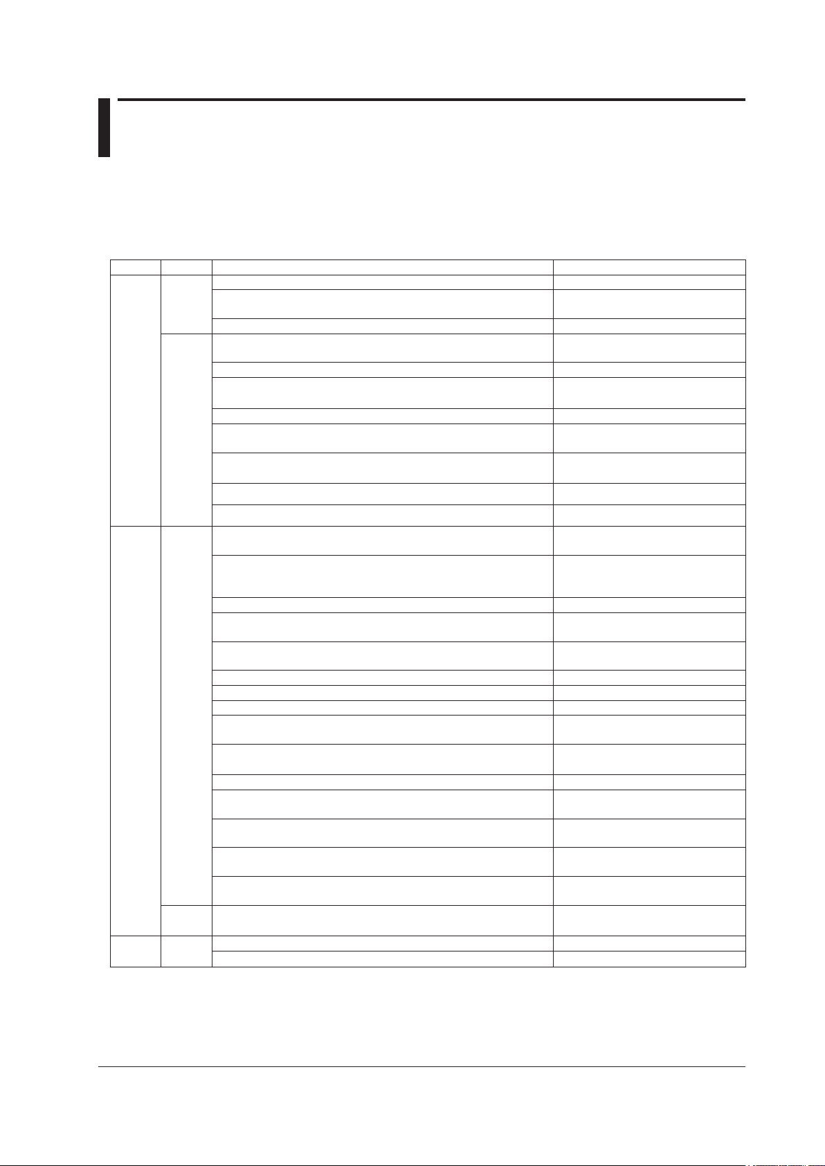
Edition DX Additionandchangetofunctions Referto
5 Release
number 3
(Version
3.0x)
Divided the setting mode displays with tabs. All setting displays
Added method for switching from setting mode to basic setting
mode.
Section 2.14
Improved numeric input operation. Numeric input display
Added the ability to input the following characters: [ ] and :. Character string input display
Added new input type (GOST; /N3 option). Section 3.3
Increased measurement range for TC Type N. Section 13.5
Custom display. IM04L41B01-04E
Multi Batch (/BT2 option). IM04L41B01-03E
Alarm level display. Section 3.7
Alarm annunciator. Section 3.12
Common alarm (/F1 option). Section 2.9
32-character tag comments and 16-character tag numbers. Section 5.2
Faster display update interval. Section 3.1
Secondary trend interval changeable during recording. Section 5.3
Added 15-, 20-, and 30-minute event data sample rates. Section 6.1
Fine grid. Sections 4.2 and 4.3
Auto zone display. Sections 4.2 and 4.3
Indication that the DX is waiting for a trigger. Section 1.3
Decimal point types “Point” and “Comma”. Section 2.13
Added favorite key operations. Section 5.15
Data searching with date and time. Section 4.3
Historical trend relative time display, auto span display, and top
channel display.
Section 4.3
Number of batch text fields changed to 24. Section 6.3
The start recording screen appears when you press the start key
while using the batch function.
Section 6.3
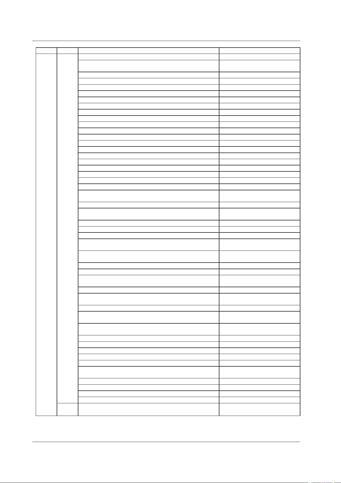
Changed contents of the system and network information displays. Section 2.5
Limits on setting load function. Section 8.1
Event switch. Section 7.1
Added “CommentDisplay” and “FavoriteDisplay” actions to the event
action function.
Section 7.1
Remote control contact input changed from operating on Close to
operating on Open (/R1 and /PM1 options).
Section 7.1
Match time timer reset (/M1 and /PM1 Options). Section 7.1
Added “Year” to match time timer conditions (/M1 and /PM1 options). Section 7.1
Match time timer usable for TLOG computation (/M1 and /PM1
options).
Section 9.1
Stacked bar graphs for report data (/M1 and /PM1 options). Section 4.10
Added recording condition variables to equations (/M1 and /PM1
options).
Section 1.8
Added USB barcode reader support (/USB1 option). Section 2.11
Saving of data from the internal memory to USB flash memory or a
CF card (/USB1 option).
Section 2.12
Added data searching, report layout display, a print button, and an
FTP link to the Web server function.
Section 1.5 in IM04L41B01-17E
Modbus register map expansion and floating-point data writing. Section 6.3 in IM04L41B01-17E
Only send alarm e-mails when an alarm has occurred. Section 1.4 in IM04L41B01-17E
Added tag and channel number to alarm e-mails. Section 1.4 in IM04L41B01-17E
E-mail transfer authentication (Pop Before SMTP). Section 1.4 in IM04L41B01-17E
“°C” displayed in e-mails and the Web settings. Section 1.5 in IM04L41B01-17E
Added the ability to input the square and cube characters (² and ³) in
communications (only for English, German, and French).
Appendix 3 in IM04L41B01-17E
Added FTP data transfer wait operation. Section 1.7 in IM04L41B01-17E
FTP server directory output format can be set to MS-DOS and UNIX. Section 1.6 in IM04L41B01-17E
EtherNet/IP. IM04L41B01-18E
PROFIBUS-DP (/CP1 option). IM04L41B01-19E
Style
number 3
Changed the boot ROM. -
DX’s Version and Functions Described in This Manual