YOKOGAWA 53005-E User manual

Printed in JAPAN 2012/05
Model: 53005/53006
Emission Thermometer
User’s Manual
Tachihi bldg, No.2, 6-1-3 Sakaecho, Tachikawa-shi, Tokyo, 190-8586 Japan
Phone:+81-42-534-1413 Facsimile:+81-42-534-1438
YOKOGAWA EUROPE B. V. (THE NETHERLANDS)
Euroweg 2, 3825HD, Amersfoot, THE NETHERLANDS
Phone: 31-88-4641000, Facsimile: 31-88-4641111
Compliance with the Radio Waves Act (Republic of Korea)
This product complies with the Radio Waves Act (Republic of Korea).
Note the following when using the product in Republic of Korea.
The product is for business use (Class A) and meets the electromagnetic
compatibility requirements.The seller and the user must note the above
point and use the product in a place except for home.
Registration No:
Equipment Name:
Trade Name:
Manufacturer:
Country of Origin:
KCC-REM-IMY-EEN326
Emission Thermometer
Yokogawa Meter & Instruments Corporation
Japan
┏

2
introduction ・・・・・・・・・・・・・・・・・・・・・・・・・・・
Safe Usage ・・・・・・・・・・・・・・・・・・・・・・・・・・・
Warnings & Caution on Environment and Usage ・・・・・・・・・・・
Specifications ・・・・・・・・・・・・・・・・・・・・・・・・・・
Name of Components ・・・・・・・・・・・・・・・・・・・・・・・
Operation ・・・・・・・・・・・・・・・・・・・・・・・・・・・・
Selection of Display Function ・・・・・・・・・・・・・・・・・・・
Selection of Temperature Unit ・・・・・・・・・・・・・・・・・・・
Default Value of Each Setting ・・・・・・・・・・・・・・・・・・・
Field of View ・・・・・・・・・・・・・・・・・・・・・・・・・・・
Setting/Resetting the Upper/Lower Limit Temperature Alarm ・・・・・・
[53005]
Recording Measured Temperature ・・・・・・・・・・・・・・・
・Record Measured Temperature(MEM.mode) ・・・・・・・・・・
・Call Temperature Record(CALL mode) ・・・・・・・・・・・・
Emissivity Setting ・・・・・・・・・・・・・・・・・・・・・・・
[53006]
Date and Time Setting ・・・・・・・・・・・・・・・・・・・・・
Emissivity Setting ・・・・・・・・・・・・・・・・・・・・・・・
Recording Measured Temperature ・・・・・・・・・・・・・・・・
・Record Measured Temperature(MEM.mode) ・・・・・・・・・・
・Call Temperature Record(CALL mode) ・・・・・・・・・・・・
・Delete All the Temperature Records ・・・・・・・・・・・・・・
Continuous Measurement ・・・・・・・・・・・・・・・・・・・・
USB Connection ・・・・・・・・・・・・・・・・・・・・・・・・
Trouble Shooting ・・・・・・・・・・・・・・・・・・・・・・・・・
Maintenance/Batteries ・・・・・・・・・・・・・・・・・・・・・・
Measures for Adoministration of the Pollution Control of
Electronic Information Products of the People's Republic of China ・・・
2
3
4
5
6
8
9
9
9
10
11
12
13
13
13
13
14
15
17
18
18
18
19
19
20
21
22
24
Thank you very much for purchasing Thermometers products.This device is a non-contact
thermometer to convert the infrared energy emitted from the surface of an object into
temperature.This thermometer measures the surface temperature of solid and liquid with-
out contacting them. The temperature of gas cannot be measured by this thermometer.
Contents
Introduction
• Please make sure the model you purchased is the one you specified.
• Please read the manual thoroughly before using the Products for correct
usage.
• After reading this manual,please retain it for future reference.
• YOKOGAWA is not liable for any incidental or consequential damages or
losses including losses of data or changes of measurement,arising from
accident, misuse or abnormal conditions of operation or handling.
53005-6E12.5.1210:59AM ページ2

3
This product is not a clinical thermometer
and therefore, can not be used for medi-
cal purposes.
Do not look into the laser beam, nor point
it directly at eyes. Even the reflection is
harmful. This laser may cause eye injury or
damage to your health.
Use of controls or adjustments or perfor-
mance of procedures other than those
specified herein may result in hazardous
radiation exposure.
Safe Usage
When operating the instrument, be sure to observe the cautionary notes given below
to ensure correct and safe use of the instrument. If you use the instrument in any way
other than as instructed in this manual, the instrument’s protective measures may be
impaired.
Yo kogawa is by no means liable for any damage resulting from use of the instrument in
contradiction to these cautionary notes.
This symbol signifies that improper usage may
result in injuries or damage.
!Caution:
! CAUTION
! CAUTION
! CAUTION
53005-6E12.5.1210:04AM ページ3

4
Safe Usage
Environmental Warnings –– Warning –– Caution
_Environmental warninngs/Cautions
KEEP THE THERMOMETER
AWAY FROM DROPPING WATER
AND DO NOT USE IN WATER.
This thermometer is not water-proof-
ing. Usage in such environments
may cause irreparable damages.
AVOID MEASURING SHINY OB-
JECTS.
Shiny objects reflect surrounding
temperatures. As this thermometerís
sensitivity to emissivity is fixed, the
displayed temperature could differ
form the actual temperature of ob-
jects that have different emissivity
values.
DO NOT LET THE THERMOM-
ETER TOUCH THE OBJECT THAT
IS BEING MEASURED.
This product is a non-cotact
themometer. Touching high-tem-
perature object may cause deforma-
tion of the meter, irreparable dam-
age or incorrect measurement.
KEEP THE THERMOMETER
AWAY FROM DIRECT SUNLIGHT,
DUST,HIGH TEMPERATURES
AND HIGH HUMIDITY DURING
USE AND STORAGE.
This may cause irreparable damage
or incorrect measurement.
DO NOT TOUCH THE FILTER.
Do not let a solid or sharp object
touch the filter and do not insert for-
eign objects into the filter.These may
cause incorrect measurement.
USE THE SPECIFIED BATTERIES.
Use of the other batteries may cause
irreparable damage or incorrect
measurement.
Usage Warnings –– Warning –– Caution
GGGGGGGGG
KEEP THE THERMOMETER
AWAY FROM SUDDEN CHANGE
IN AMBIENT TEMPERATURE.
Sudden temperature change may
cause incorrect measurement. Start
measurement when temperature
has become stable after leaving the
meter for a while.
KEEPTHE THERMOMETER AWAY
FROM STRONG ELECTROMAG-
NETIC SOURCES.
Usage in such environments may
cause irreparable damage or incor-
rect measurement.
DO NOT DROP THIS THERMOM-
ETER NOR GIVE A STRONG IM-
PACT TO IT, WHICH MAY CAUSE
IRREPARABLE DAMAGE OR IN-
CORRECT MEASUREMENT.
DO NOT BRING THE THERMOM-
ETER CLOSE TO ELECTRICALLY
CHARGED OBJECTS.
This may cause irreparable damage
or incorrect measurement.
53005-6E12.5.1210:04AM ページ4

5
Specifications
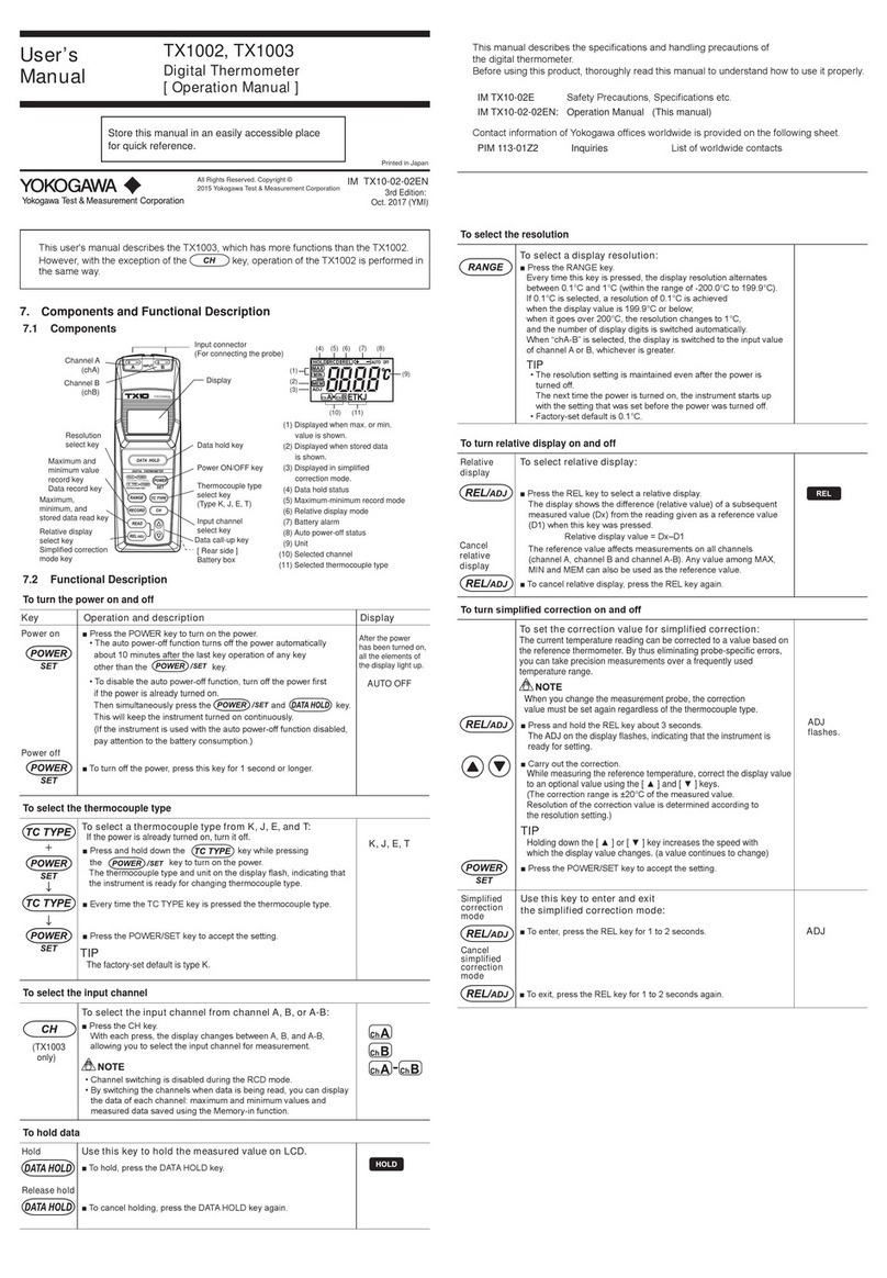
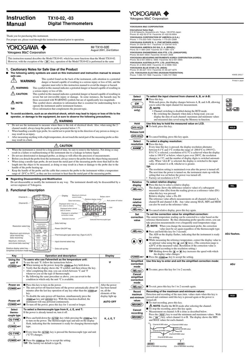
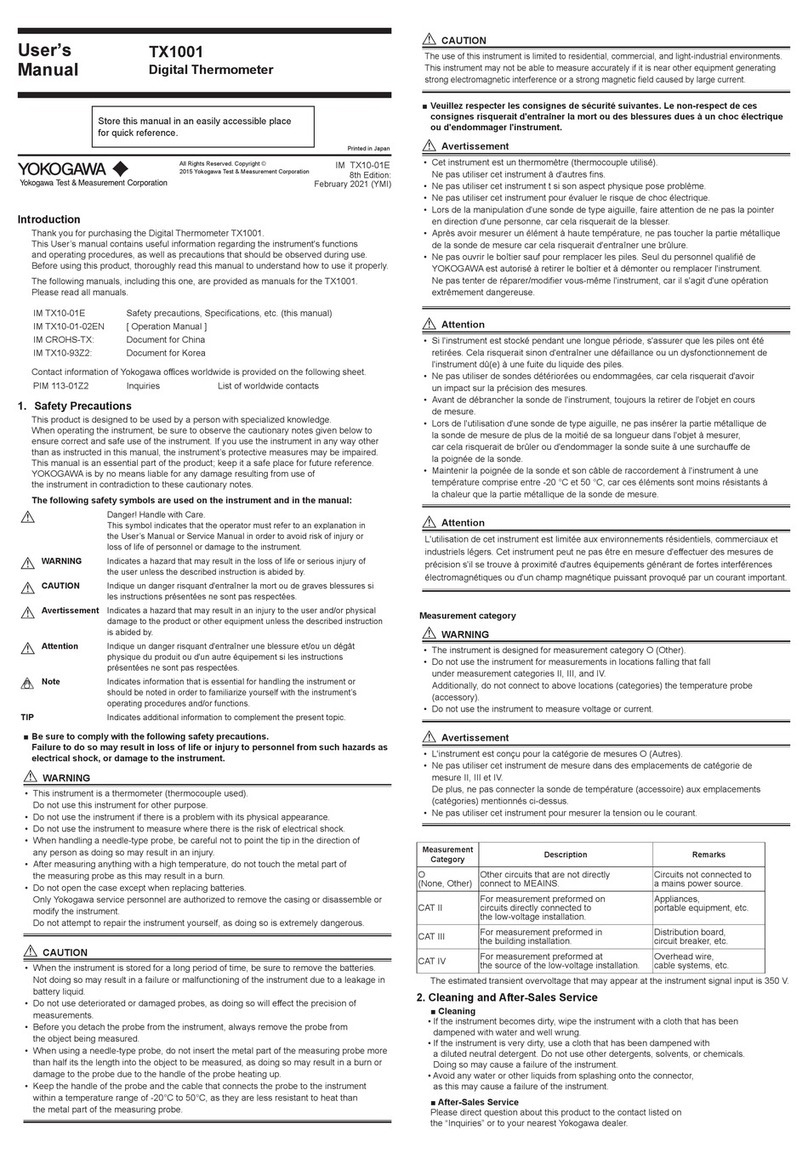
Accessories : AA battery ×2pcs., user’s manual, exclusive protective case
USB cable (Only for 53006)
Optional : Blackbody tape (Maximum available temperature 250℃)
Compliant standards.
IEC 60825-1
EN 60825-1
US 21 CFR 1040.10 and 1040.11
EN 61326-1
※Specifications may change without prior notice.
Model 53005-E 53006-E
Measuringrange − 30to600℃
Fieldofview □ 30/1000mm(D:S=33:1)
Optics Silens
Sensingelement Thermopile
Wavelength 8to14 μ m
Responsetime 0.5sec. / 90%
Accuracy(ε≒ 0.95) − 30.0to0℃:± 3℃、0.1to200℃:± 2℃、
201to600℃:± 1%
Repeatability ± 1℃ofreadingvalue
Displayresolution − 30.0to199.9℃:0.1℃、200to600℃:1℃
Sightingmethod Coaxallasermarker(Class2)
HOLDtime 15seconds
Continuousmeasurementmode
− ON/OFFSelectable
USBoutput − ○
Memory 1-pointmemory 35-pointmemory
High/LowAlarmLED/Buzzer AlarmLED/BuzzerON/OFFSelectable
Emissivity(ε)Adjustment 0.95/0.85/0.70Selectable ε Adjustable
(0.30to1.20/0.01step)
Displayfunction NOR / MAX / MIN
Powersupply AABattery×2pcs
Batterylife Approx.15Hours(Withmaxload)
Ambienttemperature 0to50℃
Ambienthumidity 35%to85%Rh(Withoutduecondensation)
Storagetemperature/humidity − 10to60℃/35%to85%Rh
Material ABS/TEEE
Dimension H × W × D = Approx.182 × 56 × 38mm
Weight Approx.250g(Includingbatteries)
53005-6E12.5.1210:04AM ページ5

6
* There is no button to turn ON/OFF the supper supply.
Name of Components
53005-6E12.5.1210:04AM ページ6

7
Satety Precautions for Laser
Products
This Instrument uses a laser
light source. This instrument is
a Class 2 laser product as de-
fined by IEC60825-1 Safety of
Laser Products-Part1: Equip-
ment classification and require-
ments. In addition, this instru-
ment complies with 21 CFR
1040.10 except for deviations
pursuant to Laser Notice No.50,
dated June 24, 2007.
DO NOT STARE INTO BEAM.
CLASS 2 LASER PRODUCT.
53005-6E12.6.15:04 PM ページ7

8
Pressing the MEASURE button to turns
ON the power supply. A laser beam emit-
ted and the measurement starts.
In the Normal Measurement mode,
the units takes measurement while
MEASURE button is pressed.
Temperature can be measured while the MEASURE button is being pressed.
Set the bettery supplied as an accessory and operate the unit according to the folloowing procedure.
1
Point the laser beam at a measurement
object and aim it at the center of the area to
be measured. For the distance from this
thermometer to the measuring object, re-
fer to page10.
2
When the MEASURE button is released,
the “MEAS” and laser beam symbols
go out and “HOLD” and “C (゚F)” sym-
bols light up. After the last temperature
value is displayed for 15seconds (HOLD
mode), the power is automatically
turned OFF.
3
Operation
53005-6E12.5.1210:04AM ページ8

9
Each time the ▼/MAX/MIN button is pressed, the display function is switched in order of NOR., MAX,
and MIN.
NOR. :“ε” is displayed at the bottom of LCD and the currently set emissivity is displayed on the sub-display.
MAX: “MAX” is displayed at the bottom of LCD and the maximum value during measurement is displayed
on the sub-display.
MIN: “MIN” is displayed at the bottom of LCD and the minimum value during measurement is displayed
on the sub-display.
Selection of display function
Default value for each setting (at the time of shipment)
53005-E 53006-E
Displayfunction NOR.
Maximumtemperaturealarm Temperaturesetting:600℃
Function:OFF
Minimumtemperaturealarm Temperaturesetting:− 30℃
Function:OFF
Emissivity(ε) 0.95
Memory Nothing
Continuousmeasurementmode − OFF
53005-6E12.5.1210:04AM ページ9

10
For the non-contact thermometer (infrared thermometer), the field of view (spot size) is specified
depending on the distance from the thermometer to the measuring object as shown below. The temperature
value displayed is the average temperature within the spot size.To take an accurate measurement, check
the correlation between the size of object and the distance to it.
[Field of View]
*Remarks
ex.) The average temperature of surface of the square 90mm in diameter is measured at a distance
of 3000mm away from the measuring object.
*The laser beam points center of the field of view. The laser marker functions as a sighting method
and not a sensing element.
*It is possible to take temperatures with this thermometer at a distance of 3,000mm or more away from
the measuring object, unless there is any obstacle. However, please note that the measuring field of view
enlarges in proportion to the measuring distance.This thermometer has an optical resolution of 33:1
[D(Distance to the measuring object):S(Spot size)].
[For Correct Measurement]
The optical resolution values stated in “Field of View” are at minimum 90% energy. The size of measuring
object should be sufficiently larger than the field of view (spot size) shown in the above illustration.
Please keep away from target as far as you can within spot ratio when you measure high temperature.
Sudden ambient temperature change may cause thermometer display value error. In this case, please
keep thermometer for a while until display value error may be corrected.
Field of View
500
1000
2000
□20 □30 □60
D:S=33:1
[Unit:mm]
3000
□90
OpticalAxis/LaserMarker
OK NG
CORRECT
The measuring object is
bigger than the field of view.
INCORRECT
The measuring object is smaller than the
field of view. The temperature of background
influences the measuring value.
53005-6E12.5.1210:04AM ページ10

11
1
Pressing the MEASURE button blinks
“ALM”. Then,“ON”or“OFF” (currently
set status) is displayed on the top of
LCD and “AL-H” is displayed on the
sub-display. (The High alarm is set up.)
2
Press the ▼/MAX/MIN or
▲ /MAX/MIN button to select ON or
OFF, and then press the MEASURE
button to confirm the setting.
When OFF is selected, the display
shifts to the setting for the Low
temperature alarm.
3
Press the SET button
while the power is ON.
The alarm temperature is displayed on
the top of LCD by selecting ON.
Press the ▼/MAX/MIN or
▲/MAX/MIN button to select ON or
OFF, and then press the MEASURE
button to confirm the setting.
When the setting has been completed,
the display shifts to the setting for the
Low temperature alarm.
4
For the setting/resetting of the Low temperature alarm, the above steps can be
appliedexcluding that “AL-H” on the sub-display is changed to “AL-L” in step 2 and later.
When the lower limit setting has been completed, the mode is changed to HOLD.
When the upper and lower limit alarms are set, “HI” and “LO” lamps are lit on the display.
Note) The High alarm value cannot be set to the value less than the setting for the Low
temperature alarm, and the Low alarm value cannot be set to the value more than the
setting for the High temperature alarm.
Setting/Resetting the High/Low Temperature Alarm
When the measured temperature exceeds the High alarm value, the alarm LED blinks in red and a
buzzer (high tone) sounds. When it is below the Low alarm value, the alarm LED blinks in green and
a buzzer (low tone) sounds. The “High alarm” is set up first, and then the “Low alarm”.
Set up the alarms according to the following steps.
Pressing the SET button displays
“ALM” on the top of LCD.
(Regarding 53006, the display is
switched in order of “ALM”, “EMS” and
“TIME” each time the SET button is
pressed.)
SET
53005-6E12.5.1210:04AM ページ11

12
53005
■
P.13 Recording Measured Temperature
□
Record Measured Temperature (MEM.Mode)
□Call
Temperature Record (CALL Mode)
■
P.13 Emissivity Setting
53005-6E12.5.1210:04AM ページ12

13
[Record measured temperature/ MEM. mode]
After “CALL” is displayed on the sub-
display, “MEM” blinks on the display
and the temperature value that had
been displayed on the sub-display
when the ▲/MEM./CAL button was
pressed starts to light up. Then the
value is stored in memory.
After the data is stored, the mode is
changed to HOLD.
1
1 Press this button for 2
seconds or more while
the power is ON.
[Call temperature record/CALL mode]
“CALL” is displayed on the sub-
display, and then the stored
temperature data displayed.
1
Press the MEASURE button to
terminate the CALL mode. Then, the
normal measurement mode is
restored.
2
1 Press this button for
less than 2 seconds
while the power is ON.
Emissivity ( ε) refers to the ratio of infrared energy emitted from all the object surfaces. All objects has their
own emissivity, which changes depending on the surface conditions and object temperature. This thermometer
has 3 fixed emissivities. Refer to the following examples.
0.95...Food, rubber, plastic, paintwork, etc.
0.85...Temperature of Frozen food can be measured almost accurately.
0.70...Temperature of oxidized metal surfaces can be measured almost accurately.
The displayed temperature could differ from the actual temperature of objects that have different emissivity. In
such cases, regard the displayed temperature as a rough standard. When you wish to measure shiny metal
surfaces, put a piece of optional blackbody tape ( ε=0.95) on the surface of the measured object.
Emissivity Setting
When the emissivity (0.95/0.85/0.7) is selected according to “DIP switch setting” in page 7, the
temperature value converted into the selected emissivity is displayed.
Recording Measured Temperature
53005 can store one (1) temperature measurement data.
Perform the following steps.
53005-6E12.5.1210:04AM ページ13

14
53006
■
P.15 Date and Time Setting
■
P.17 Emissivity Setting
■
P.18 Recording Measured Temperature
□
Record Measured Temperature (MEM.Mode)
□
Call Temperature Record (CALL Mode)
□
Delete All the Temperature Records
■
P.19 Continuous Measurement
■
P.20 USB Connection
53005-6E12.5.1210:04AM ページ14

15
The LCD display is switched in order
of “ALM”, “EMS” and “TIME” each
time the SET button is pressed.
Display “TIME” on the LCD.
1
After “TIME” blinks, “YEAR” blinks.
Then, the display is automatically
shifted to the state that “YEAR”
lights up and the dominical year
blinks.
2
Press the ▼/MAX/MIN or
▲ /MEM./CAL button to adjust the
year. Then press the MEASURE
button to fix the setting.
After the setting, the set year blinks
on the LCD.
3
1 Press this button while
the power is ON.
After the set year blinks, “date”
blinks, then the display is
automatically shifted to the state that
“date” lights up, the left 2 digits of
the clock (month) blinks and the right
2 digits (day) lights up.
The left 2 digits of the clock indicate
a “month” and the right 2 digits
indicate a “day”.
4
5Press the ▼/MAX/MIN or
▲/MEM./CAL button to adjust the
month. Then press the MEASURE
button to fix the setting.
After the setting, the right 2 digits of
the clock blink. Then go to the “date”
setting.
Date and time can be set in 53006.
Perform the following steps.
*The setting returns to the default if batteries are removed.
To the page that follows
Date and Time Setting
SET
53005-6E12.5.1210:04AM ページ15

16
Press the ▼/MAX/MIN or
▲/MEM./CAL button to adjust the
month. Then press the MEASURE
button to fix the setting.
After the setting, the set month and
date blink on LCD.
6
After the set date blinks, “TIME”
blinks, and then the display is changed
to the state that the time lights up, the
left 2 digits of the clock (hour) blinks
and the right 2 digits (minute) light up.
7
8Press the ▼/MAX/MIN or
▲/MEM./CAL button to adjust the
hour. Then press the MEASURE
button to fix the setting.
After the setting, the right 2 digits of
the clock start to blink for the
“minute” setting.
Press the ▼/MAX/MIN or
▲/MEM./CAL button to adjust the
hour. Then press the MEASURE
button to fix the setting.
Then, the set time blinks on LCD.
9
After the set time blinks, “SEC” start to
blinks and then the display is automati-
cally changed to the state that “SEC”
lights up and the “ ” blinks on the
clock.
10
To the page that follows
53005-6E12.5.1210:04AM ページ16

17
When the MEASURE button is
pressed, the second is set to 0.
Press the button so that the second
is accurately set. The date and time
setting is now complete. After “ ”
blinks on LCD, the mode is switched
to HOLD.
11
Emissivity setting
Emissivity (ε) refers to the ratio of infrared energy emitted from all the object surfaces. All objects has
their own emissivity, which changes depending on the surface conditions and object temperature. The
emissivity setting for this thermometer can be changed, so that emissivity can correspond to a measured
object and more accurate values can be measured.
Objects with low emissivity (ex: shiny metal surfaces) reflect the surrounding temperatures due to the
high reflectivity. If an object other than the measured object such as a high-temperature object exists on
the periphery, temperature for the other object is reflected, which will cause incorrect measurement.
Thus, it is necessary to block off the obstacle.
Although the maximum emissivity is primarily 1.00, the value up to 1.20 can be set for this
thermometer in consideration of convenience.
The LCD display is switched in order
of “ALM”, “EMS” and “TIME” each
time the SET button is pressed.
Display “EMS” on the LCD. (The
currently set emissivity is displayed on
the sub-display.)
1
After “EMS” blinks, the currently set
emissivity appears on LCD. (The
currently set emissivity is displayed
on the sub-display.)
2
Press the ▼/MAX/MIN or
▲/MEM./CAL button to display the
emissivity to be set up. The setting is
completed by pressing the
MEASURE button.
After the setting, the mode is
changed to HOLD.
3
1 Press this button
while the power is ON.
Emissivity Setting
SET
53005-6E12.5.1210:04AM ページ17

[Record measured temperature/ MEM. mode]
53006 can store 35 temperature measurement data.
Perform the following steps.
After “CALL” is displayed on the sub-
display, “MEM” blinks on the display
and a memory No. lights up on the
sub-display. Then the temperature
value that had been displayed when
the ▲ /MEM./CAL button was
pressed is stored in memory.
After the data is stored, the mode is
changed to HOLD.
1
*If the number of stored data has exceeded the capacity, “FULL” lights up on LCD.
1 Press this button for 2
seconds or more while
the power is ON.
[Call temperature record/CALL mode]
“CALL” is displayed on the sub-
display, and then the latest stored
temperature data and the
corresponding memory No. are
displayed.
*Data cannot be called during the
continuous measurement mode.
1
When the memory No. is changed,
the corresponding temperature data
is displayed in order.
2
Press the MEASURE button to
terminate the CALL mode. Then, the
normal measurement mode is
restored.
3
1 Press this button for
less than 2 seconds
while the power is ON.
18
Recording Measurement Temperature
To the page that follows
53005-6E12.5.1210:04AM ページ18

[Delete all the temperature records]
“CLR” is displayed on LCD, and all the
temperature records are deleted.
After the deletion, the HOLD mode is
restored.
1
Press the SET button
during the CALL mode.
When the MEASURE button is
pressed while the DIP switch is adjusted
to the CONT. side (Refer to “DIP switch
setting” in page 7.), “CONT” is lit on
LCD and continuous measurement is
started. Measurement continues even if
releasing the MEASURE button.
1
When the MEASURE button is
pressed again or the DIP switch is
changed over to the NOR. side, the
mode is changed to HOLD.
2
For 53006, continuous measurement can be performed without pressing the MEASURE button.
Perform the following steps.
Press once
19
*Laser beam is not radiated during the continuous measurement mode.
Continuous Measurement
Press once
NOR. CONT.
NOR. CONT.
SET
53005-6E12.5.1210:04AM ページ19

20
USB Connection
53006 is connectable to PC with the exclusive software and included USB cable. The exclusive
software is downloadable at following Web address.
URL http://tmi.yokogawa.com/products/portable-and-bench-
URL instruments/thermometers/53005-53006-emission-thermometer/
《Adaptable hardware》
The exclusive software activates on DOS/V PC with USB connector and installed Windows 2000
or XP. USB Rev1.1.
Note:Macintosh is not acceptable.
The outlook of exclusive software
1: Software is capable of reading, revising and writing of data inside thermometer.
2: PC can read all date instantly on thermometers continuous mode.
3: Output all data by CSV format.
4: Set up each parameters.
Clock
Emissivity
Change memory capability
For the details, please see the exclusive software.
Connection
1: Download and install the exclusive software into PC.
Please make sure the PT-U80 turns off when connecting PC.Otherwise stored data is deleted.
2: Connect USB cable to PC.
3: Set up the exclusive software.
4: Push MEASURE switch on thermometer.
USB cable provides power to thermometer in connecting.
Shut down
1: Finish the exclusive software.
2: Disconnect USB cable from PC with PO indication.
3: Disconnect USB cable from thermometer.
53005-6E12.5.1210:04AM ページ20
This manual suits for next models
1
Table of contents
Other YOKOGAWA Thermometer manuals

YOKOGAWA
YOKOGAWA TX1002 User manual

YOKOGAWA
YOKOGAWA TX1001 User manual

YOKOGAWA
YOKOGAWA TM10 User manual

YOKOGAWA
YOKOGAWA TX1001 User manual

YOKOGAWA
YOKOGAWA TX10-02 User manual

YOKOGAWA
YOKOGAWA TX1002 User manual

YOKOGAWA
YOKOGAWA 53008 User manual

YOKOGAWA
YOKOGAWA TM20 User manual

YOKOGAWA
YOKOGAWA TX10-01 User manual

YOKOGAWA
YOKOGAWA TX1001 User manual