YOKOGAWA TX10-02 User manual

Instruction
Manual
IM TX10-02E
August 2001, 2nd Edition
Thank you for purchasing this instrument.
For proper use, please read through this instruction manual prior to operation.
TX10-02, -03
Digital Thermometers
This instruction manual describes the Model TX10-03, which has more functions than the Model TX10-02.
However, with the exception of the key, operation of the Model TX10-02 is performed in the same
;
;
;
;
1. Cautionary Notes for Safe Use of the Product
■The following safety symbols are used on this instrument and instruction manual to ensure
safe use.
WARNING
This symbol found on the back of the instrument, calls attention to a potential
danger or hazard capable of resulting in a serious injury or loss of life, and the
operator must refer to this instruction manual to avoid the danger or hazard.
WARNING:This symbol in this manual indicates a potential danger or hazard capable of resulting in
a serious injury or loss of life.
CAUTION:This symbol in this manual indicates a potential danger or hazard capable of resulting in
severe but not irreversible injury or damage. In some instances, the hazards may be
those associated with WARNING symbols but are of significantly less magnitude.
NOTE:This symbol draws attention to information that is essential for understanding how to
operate the instrument and/or instrument features.
TIP:Gives information that complements the present topic.
■To avoid accidents, such as an electrical shock, which may lead to injury or loss of life to the
operator, or damage to the equipment, be sure to observe the following precautions.
WARNING
•Do not use the instrument to measure where there is the risk of electrical shock. Also, when using the 2-
channel model, always keep the probe-to-probe potential below 1 V.
•When handling a needle-type probe, be careful not to point the tip in the direction of any person as doing so
may result in an injury.
•After measuring anything with a high temperature, do not touch the metal part of the measuring probe as this
may result in a burn.
CAUTION
•When the instrument is stored for a long period of time, be sure to remove the batteries. Not doing so may
result in a failure or malfunctioning of the instrument due to a leakage in battery liquid.
•Do not use deteriorated or damaged probes, as doing so will effect the precision of measurements.
•Before you detach the probe from the instrument, always remove the probe from the object being measured.
•When using a needle-type probe, do not insert the metal part of the measuring probe more than half its the
length into the object to be measured, as doing so may result in a burn or damage to the probe due to the
handle of the probe heating up.
•Keep the handle of the probe and the cable that connects the probe to the instrument within a temperature
range of -20°C to 50°C, as they are less resistant to heat than the metal part of the measuring probe.
■Regarding Disassembling and Modification
Do not disassemble or modify the instrument in any way. The instrument should only be disassembled by a
service engineer of Yokogawa.
2. Functional Description
Thermocouple type select key (Type K/J/E/T)
Maximum and minimum
value record key
Data record key
Relative display select key
Simplified correction mode key Data call-up key
Power ON/OFF key
Data hold key
Resolution select key
Channel A
Channel B
Display
Maximum, minimum,
and stored data read key Input channel select key
AUTO
OFF
MAX
HOLD RCD REL
MEM
ADJ
A
MIN
B
ETKJ
Battery alarm
Relative display mode
Selected thermocouple type
Auto power-off status
Unit
Displayed in simplified
correction mode.
Displayed when stored
data is shown.
Displayed when max.or
min. value is shown.
Data hold status
Maximum-minimum
record mode
Selected channel
Select
channel
;
;
;;
;;
(TX10-03
only)
To select the input channel from channel A, B, or A-B:
■Press this key.
With each press, the display changes between A, B, and A-B, allowing
you to select the input channel for measurement.
NOTE:
•Channel switching is disabled during the RCD mode.
•By switching the channels when data is being read, you can
display the data of each channel: maximum and minimum values
and measured data saved using the Memory-in function.
AB
A
B
Hold
Release hold
Use this key to hold the measured value on LCD.
■To hold, press this key.
■To cancel holding, press this key again.
HOLD
Select
resolution To select a display resolution:
■Press this key.
Every time this key is pressed, the display resolution alternates
between 0.1°C and 1°C (within the range of -200.0°C to 199.9°C).
If 0.1°C is selected, a resolution of 0.1°C is achieved when the display
value is 199.9°C or below; when it goes over 200°C, the resolution
changes to 1°C, and the number of display digits is switched automati-
cally. When “chA-B” is selected, the display is switched to the input
value of channel A or B, whichever is greater.
TIP:
•The resolution setting is maintained even after the power is turned off.
The next time the power is turned on, the instrument starts up with the
setting that was set before the power was turned off.
•Factory-set resolution is 0.1°C.
Relative
display
Cancel
relative
display
To select relative display:
■Press this key to select a relative display.
The display shows the difference (relative value) of a subsequent
measured value (Dx) from the reading given as a reference value (D1)
when this key was pressed.
Relative display value = Dx–D1
The reference value affects measurements on all channels (channel A,
channel B and channel A-B). Any value among MAX, MIN and MEM
can also be used as the reference value.
■To cancel relative display, press this key again.
REL
Set
correction
value
To set the correction value for simplified correction:
The current temperature reading can be corrected to a value based on the
reference thermometer. By thus eliminating probe-specific errors, you can
take precision measurements over a frequently used temperature range.
NOTE:When you change the measurement probe, the correction
value must be set again regardless of the thermocouple type.
■Press and hold this key for 3 seconds.
The ADJ on the display flashes, indicating that the instrument is ready
for setting.
■While measuring the reference temperature, correct the display value to
an optional value using the and keys. (The correction range is
±20°C of the measured value. Resolution of the correction value is
determined according to the resolution setting.)
TIP:Holding down the or key increases the speed with which
the display value changes.
■Press the key to accept the setting.
ADJ flashes.
Key Operation and description Display
Power on
Power off
■Press this key to turn on the power.
•The auto power-off function turns off the power automatically about 10
minutes after the last key operation of any key other than the
key.
•To disable the auto power-off function, simultaneously press the
key and key. With this function disabled, the
instrument will stay powered continuously.
■To turn off the power, press this key for 1 second or longer.
After the power
has been turned
on, all the
elements of the
display light up.
AUTO OFF
Select
thermo-
couple type
+
↓
↓
To select a thermocouple type from K, J, E, and T:
If the power is already turned on, turn it off.
■Press and hold down the key while pressing the key
to turn on the power. The thermocouple type and unit on the display
flash, indicating that the instrument is ready for changing thermocouple
type.
■Every time the key is pressed the thermocouple type and unit
(°C/°F) changes.
■Press the key to accept the setting.
TIP: The factory-set default is type K.
K, J, E, T
Simplified
correction
mode
Cancel
simplified
correction
mode
Use this key to enter and exit the simplified correction mode:
■To enter, press this key for 1 to 2 seconds.
■To exit, press this key for 1 to 2 seconds again.
ADJ
Record
maximum
and minimum
values
Cancel
recording
Recording of the maximum and minimum values:
Detection and recording of the max./min. values starts when this key is
pressed and continues until this key is pressed again or the power is
turned off.
■To start recording, press this key.
NOTE: Enable the RCD mode after selecting the channel.
■To stop the recording, press this key again.
•Measurement on channel A-B is done as described below.
Press the key to read the minimum and maximum values. With
the
;
;
;;
;;
key, select channel A or B. The display shows the MIN
and MAX values for each channel.
°C
t
Channel-A MIN value Channel-A MAX value
Channel A-B MAX value Channel A-B MIN value
chA
chB
Channel-B MAX value
Channel-B MIN value
(Start of MIN/MAX recording) (End of MIN/MAX recording)
RCD
Using the
unit °F To users who use Fahrenheit as the temperature unit:
To use the unit °F, follow the instructions below.
■When turning on the power, keep the key held down.
•Verify that the display shows the °F symbol, and then release the key.
•After completing this step, you can switch between °C and °F
whenever you set the type of thermocouple.
•By following the same procedure as above, you can revert to the
condition in which only the unit °C is available.
°F
KIM3E-2002.7
Printed in Japan
YOKOGAWA M&C CORPORATION
International Sales Dept.
2-9-32 Nakacho, Musashino-shi, Tokyo, 180-8750 Japan
Phone: 81-422-52-5716 Facsimile: 81-422-55-8954
YOKOGAWA CORPORATION OF AMERICA (U.S.A.)
Phone: 1-770-253-7000 Facsimile: 1-770-251-2088
YOKOGAWA EUROPE B. V. (THE NETHERLANDS)
Phone: 31-334-64-1611 Facsimile: 31-334-64-1610
YOKOGAWA AMERICA DO SUL S. A. (BRAZIL)
Phone: 55-11-5681-2400 Facsimile: 55-11-5681-1274
YOKOGAWA ENGINEERING ASIA PTE. LTD. (SINGAPORE)
Phone: 65-6241-9933 Facsimile: 65-6241-2606
YOKOGAWA MEASURING INSTRUMENTS KOREA CORPORATION (KOREA)
Phone: 82-2-551-0660 to -0664 Facsimile: 82-2-551-0665
YOKOGAWA AUSTRALIA PTY. LTD. (AUSTRALIA)
Phone: 61-2-9805-0699 Facsimile: 61-2-9888-1844
YOKOGAWA BLUE STAR LTD. (INDIA)
Phone: 91-80-227-1513 Facsimile: 91-80-227-4270
LTD. YOKOGAWA ELECTRIC (RUSSIAN FEDERATION)
Phone: 7-095-737-7868 Facsimile: 7-095-737-7869

Memory-in
↓
↓
↓
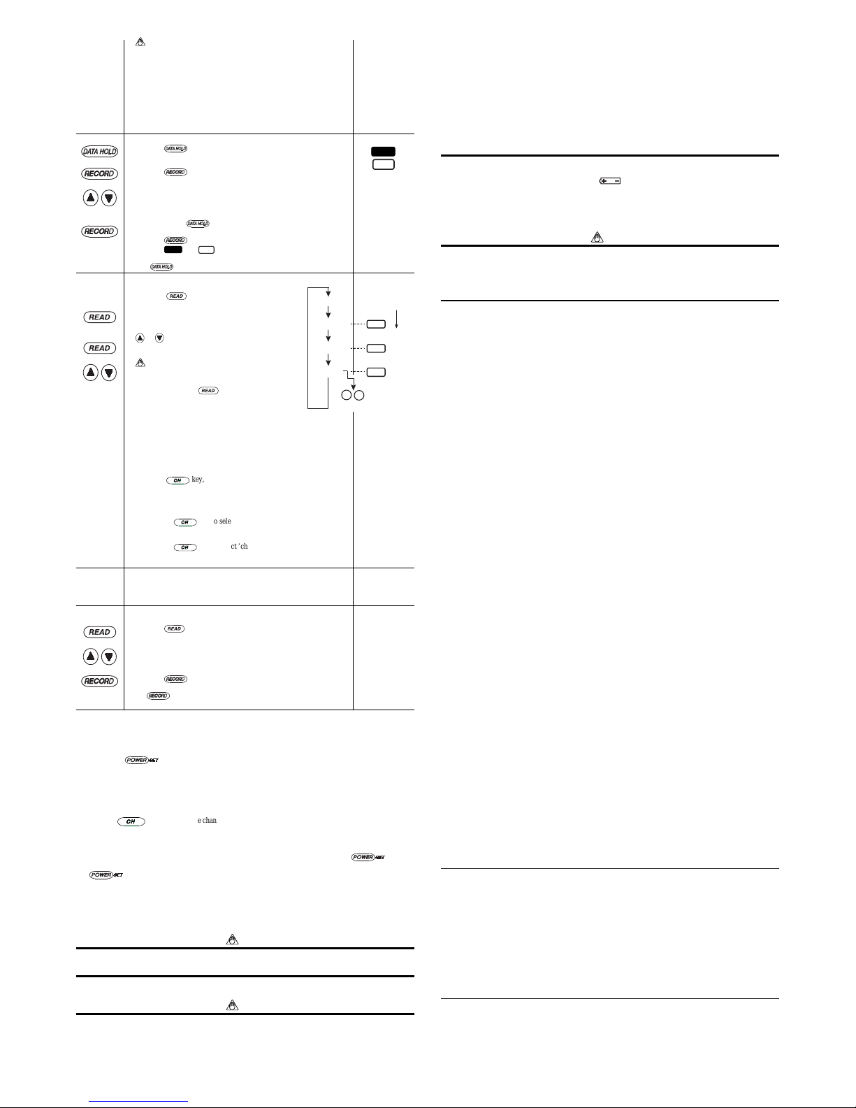
To store data in internal memory (maximum of 10 data items):
■Press the key to hold the measured value.
■Press the key.
The display automatically shows the smallest memory number under
which no data has been recorded. At this point, the MEM symbol turns
on to indicate that the thermometer is in the “Memory-in” mode.
■
Use these keys to select a desired memory number under which you want
to record data. In this step, you can also check the existing data value.
TIP:
Pressing the key while a memory number is being displayed
cancels the memory-in function (returns to measurement mode).
■Press the key to store the data.
TIP:The HOLD and
MEM
symbols indicate that the value recorded
with the memory-in function is being held and shown. Press the
key to return to normal measurement mode.
HOLD
MEM
Read
maximum
and minimum
values
Read
stored data
↓
To read maximum and minimum values and stored data
values from memory:
■When the key is pressed, the display changes
in the sequence shown in the figure on the right.
■For stored data, select the memory number using the
or key. After the memory number has been
displayed for a few seconds, the value stored in that
memory is displayed.
NOTE:
•This data reading is disabled during thermo-
couple type selecting or correction value setting.
•If you press the key when the REL mode
is active, each of the MIN, MAX and MEM
values is shown as a relative value based on the
reference value (D1).
•The number of display digits of maximum and minimum/stored
data depends on the current resolution setting, not the number of
display digits at the time when the data was measured.
Channel switching and display when data is being read (TX10-
03 only):
■
Data while measuring values from a single channel (either channel A or B)
Using the
;
;
;;
;;
key, display the channel used when the data was
measured. All of the maximum, minimum, and stored data values can
be displayed.
■Data when measuring the difference between values of two channels
(channel A and B measurement)
• Pressing the
;
;
;;
;;
key to select channel A or B shows the minimum
and maximum values, as well as the memory value, measured on that
channel.
•Pressing the
;
;
;;
;;
key to select ‘chA-chB’ displays the stored values
of the difference between channels A and B as well as the maximum or
minimum difference values.
Burnout
———— •When the probe is not connected to the input connector (or the sensor
opens), a burnout mark is displayed.
•
For the 2-channel mode, the burnout mark is displayed when the probe is
not connected to the selected channel (channel A and B, or channel A-B)
Clear stored
data
↓
↓
To clear the recording memory:
■Press the key to display stored data.
■Select the memory number you wish to clear.
■Press the key to clear the data.
To clear all the stored data in the memory at one time, press and hold
the key for 1 to 2 seconds.
TIP: This operation does not affect the maximum and minimum values.
3. Measurement
This instrument can connect any of the 4 types of thermocouples: Type K, J, E, or T (it is set to Type K at shipment
from the factory). Use an omega-type connector corresponding to the TC type for the probe.
(1) Load the batteries (see section 5, Battery Replacement).
(2) Press the key to turn on the power.
When the power has been turned on, all indications on the display light up for about 2 seconds, then a measured
value appears.
(3) Check the thermocouple type.
If you wish to change the current setting, turn off the power and follow the instructions in the section Select
thermocouple type on the previous page.
(4) Select the input channel. (TX10-03 only)
Press the
;
;
;;
;;
key and select one channel from channel A, B, and A-B (see Select channel on the previous
page).
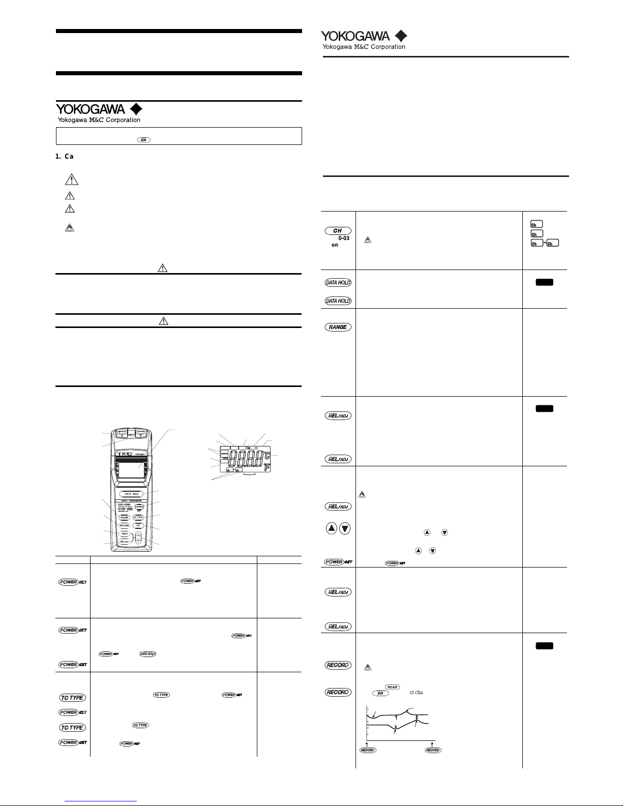
(5) Connect the probe to the input connector.
If you are using the 2-channel model (TX10-03), connect the probe(s) to the channel(s) you are using.
(6) When you have finished measurement, turn off the power by pressing the key.
•The power may be turned off by the auto power-off function during measurement. In this case, press the
key to restart the instrument and continue measurement.
•If the power is turned off and then on again, the instrument restarts with the same settings of the resolution
(0.1°C or 1°C), input channel (channel A, B or A-B) and thermocouple type (K, J, E or T) as before it was
turned off.
(7) Other operations
For other operations such as display hold, relative display, and maximum and minimum record/readout, see the
key operation list on the previous page.
NOTE
Key operation of this instrument is comparatively easy. However, it is necessary to make sure that the instru-
ment is not mistakenly set to a state other than that intended. Note that, under normal measurement, “HOLD,”
“RCD,” “REL,” “MAX,” “MIN,” and “MEM” are not displayed.
4. Precautionary Notes
NOTE
•Each probe has its own maximum and minimum operating temperatures, so ensure that its temperature does
not fall outside the specified range.
•As the probe is susceptible to corrosion, do not use the instrument for the measurement of gas or liquid, and
refrain from measuring semi-solid particles and semi-viscous substances. After measurement, wipe the
probe with a dry cloth.
•Do not apply a strong force to the upper and lower parts of the probe as doing so may result in the bending
of the probe connector.
• When using the instrument be careful not to bend, drop, or strike the measurement probe.
•When measuring surface temperature using a surface-type probe, position the probe perpendicular to the
surface of the object. Also note that the application of oil to the probe for the means of providing better
contact can improve measurement accuracy.
•When measuring non-metallic surface temperature, make sure the measurement time is long enough to
compensate for poor thermal conductivity.
• To ensure stable measurement, the instrument should not be subjected to a sudden temperature change.
•This instrument, with the exception of the connector section, is water-resistant but not waterproof. There-
fore the instrument should not be immersed in water. If it is mistakenly immersed in water, remove it
immediately and check to ensure that no water has penetrated inside the case. Although this instrument is
designed so that any water penetrating into the connector does not permeate into the circuit inside the case,
try to prevent any water entering the connector. If water does enter the connector, the burnout display may
be unavailable.
5. Battery Replacement
When the batteries approach the end of their lives, the mark appears on the display. If this mark is displayed,
replace the batteries.
To replace the batteries:
(1) Remove the battery box cover from the back of the instrument. Then replace the two AA alkaline dry batteries
(LR6).
(2) Refit the cover to the battery box.
NOTE
• When inserting batteries, be careful not to mistake the polarity as this can damage the instrument.
•When the instrument is to be stored for a long period of time, remove the batteries.
•Do not leave dead batteries in the instrument as doing so may result in a failure or malfunction of the
instrument due to a leakage in battery liquid.
•Both batteries should be replaced with new ones at the same time as replacing only one of the batteries may
result in the charge leaking from the new battery to the old.
6. Cleaning
•
If the instrument becomes dirty, wipe the instrument with a cloth that has been dampened with water and well wrung.
•If the instrument is very dirty, use a cloth that has been dampened with a diluted neutral detergent. Do not use
other detergents, solvents, or chemicals. Doing so may cause a failure of the instrument.
•
Avoid any water or other liquids from splashing onto the connector, as this may cause a failure of the instrument.
7. Maintenance Service
For maintenance or repairs, contact Yokogawa Engineering Service (see the first page).
8. Specifications
Performance Specifications
Thermocouple type K, J, E, T
Measurement channels 1ch or 2ch (2ch, multi-function model only)
Measuring range Type K: -200°C to 1372°C [-328°F to 2501.6°F]
Type J: -200°C to 1000°C [-328°F to 1832°F]
Type E: -200°C to 700°C [-328°F to 1292°F]
Type T: -200°C to 400°C [-328°F to 752°F]
Measurement resolution -200.0°C to 199.9°C: 0.1°C or 1°C (when 1°C resolution is set)
200°C or higher: 1°C
Accuracy (instrument) -200.0°C to -100.1°C: 0.1% of rdg + 1.0°C
-100.0°C to 199.9°C: 0.1% of rdg + 0.7°C
200°C or higher, or when 1°C resolution is set: 0.2% of rdg + 1°C
Temperature coefficient ±(0.015% of rdg +0.06°C)/°C
Measurement cycle Approx. 1 second (1ch model; 2ch model when performing 1ch measurement)
Approx. 2 seconds (2ch model when performing 2ch measurement; with no
range switching)
Operating environment 0°C to 50°C, 20 to 80% RH (no condensation)
Storage environment -10°C to 60°C, 5 to 95% RH (no condensation)
Power requirements Two AA alkaline dry batteries (LR6)
Battery life Approx. 450 hours
General Functions
Display Reflective LCD; 7-segment, 4-digit display and 30 character segments
Computing function MAX/MIN, REL
Difference between 2 channels (2ch model only)
Battery alarm Displayed on LCD
Key operation sound Internal buzzer sounds during key operation
Auto power-off Turns off the power 10 minutes after the last key operation (can be disabled)
Range hold function Controls the range switching between -200.0°C to 199.9°C (0.1°C resolution),
and 200°C or higher (1°C resolution).
Simple memory function Stores up to 10 data items in memory. Displays memory number and stored data
value.
Drip-proof construction Protection Class IP-54
Simplified correction function Based on the reference value entered manually
Dimensions and Weight
External dimensions Approx. 151(H) ×56(W) ×33(D) mm (excluding protrusions)
Weight Approx. 180 g (including batteries)
Compliance with Standards
EMC standards EMI (interference signal): EN55011;1998,
EN61326-1;1998+A1 (Class B, Group 1)
EMS (immunity): EN50082-1;1997,
EN61326-1;1998+A1
Emission immunity The accuracy ratings of all ranges are the sum of the accuracy levels in standard
applications and the accuracy tolerances shown below, where the overall length
of cable, including the probe, is assumed to be shorter than 3 m.
Accuracy tolerance of all available ranges: ±5% of span (Tested at 3 V/m and
for standard applications)
Accessories
Instruction manual
Two AA alkaline dry batteries (LR6)
9. Accessories (Optional)
Temperature probes (for thermocouple type K)
Model Probe type Measuring Accuracy Response Sensor Cord
range time (second) Dimenter/Length (m/m) length
900 20 rounded end -50 to 600°C 0.4% or ±1.5°C 1.4 ø3.2 / 200 1.2m
[-58 to 1112°F] (±2.7°F)
900 21 rounded end -50 to 600°C 0.4% or ±1.5°C 0.4 ø1.6 / 150 1.2m
[-58 to 1112°F] (±2.7°F)
900 22 rounded end -50 to 600°C 0.4% or ±1.5°C 1.4 ø3.2 / 500 1.2m
[-58 to 1112°F] (±2.7°F)
900 23 needle -50 to 500°C 0.4% or ±1.5°C 0.4 ø1.6 / 100 1.2m
[-58 to 932°F] (±2.7°F)
900 24 needle -50 to 500°C 0.4% or ±1.5°C1 ø2.1 / 100 1.2m
[-58 to 932°F] (±2.7°F)
900 30 Surface -20 to 250°C 0.75% or ±2.5°C2 ø15 1.2m
straight [-4 to 482°F] (±4.5°F) (temp. sensing portion)
900 31 Surface -20 to 250°C 0.75% or ±2.5°C2 ø15 1.2m
angled [-4 to 482°F] (±4.5°F) (temp. sensing portion)
900 32 Surface -20 to 500°C 0.75% or ±2.5°C2 ø15 1.2m
straight [-4 to 932°F] (±4.5°F) (temp. sensing portion)
900 33 Surface -20 to 500°C 0.75% or ±2.5°C2 ø15 1.2m
angled [-4 to 932°F] (±4.5°F) (temp. sensing portion)
2459 07 Bead TC -40 to 260°C 0.75% or ±2.5°C 1200 1.2m
[-40 to 500°F] (±4.5°F) (included cord)
2459 21 Extension cable (5 m) (90% response) * JIS: Japan Industrial Standard
2459 22 Extension cable (10 m)
930 11 Waterproof cover (5 pcs)
930 12 Carrying case
10.RegardingThis Manual
• The contents of this manual are subject to change without prior notice.
•This manual is intended to describe the functions of this instrument, not to guarantee that the functions are
suited to the particular purpose of the user.
NOTE:
• The maximum and minimum values are stored in internal memory
even after recording is cancelled. The data will be updated when
the RCD mode is enabled again.
•
If you enable the RCD mode when the REL mode is active, the
reading changes to a relative value. Nevertheless, the minimum and
maximum of measured values (Dx) are stored in internal memory.
•Recorded maximum and minimum values can be referenced even
after the power is turned off and on again because they are stored
in memory until the RCD mode is enabled next time.
•Auto power-off is cancelled during the RCD mode.
Maximum value
Stored value
Minimum value
Measured value
MAX
MEM
MIN
▼
▼
Memory number selection
chA(or chB
or chA-chB)
Source input channel
of the recorded data
This manual suits for next models
1
Table of contents
Other YOKOGAWA Thermometer manuals

YOKOGAWA
YOKOGAWA TM10 User manual

YOKOGAWA
YOKOGAWA TX1002 User manual

YOKOGAWA
YOKOGAWA TX1001 User manual

YOKOGAWA
YOKOGAWA TX1002 User manual

YOKOGAWA
YOKOGAWA DB-16 User manual

YOKOGAWA
YOKOGAWA TX1001 User manual

YOKOGAWA
YOKOGAWA TX1002 User manual

YOKOGAWA
YOKOGAWA TX10-03 User manual

YOKOGAWA
YOKOGAWA 53008 User manual

YOKOGAWA
YOKOGAWA 53005-E User manual
Popular Thermometer manuals by other brands

TFA
TFA FUN instruction manual

ThermoPro
ThermoPro TP-21 instruction manual

GHM-Messtechnik
GHM-Messtechnik GREISINGER GMH 285 operating manual

Omron
Omron MC-246 manual

Veridian Healthcare
Veridian Healthcare 09-340 quick start guide

VISIOMED
VISIOMED bewell connect MyThermo Pocket BW-MTX1 operating instructions