To record maximum and minimum values
Recording
Cancel
recording
• The maximum and minimum values are stored in internal memory
even after recording is cancelled.
The data will be updated when the RCD mode is enabled again.
• If you enable the RCD mode when the REL mode is active,
the reading changes to a relative value.
Nevertheless, the minimum and maximum of measured values (Dx)
are stored in internal memory.
• Recorded maximum and minimum values can be referenced even
after the power is turned off and on again because they are stored
in memory until the RCD mode is enabled next time.
• Auto power-off is cancelled during the RCD mode.
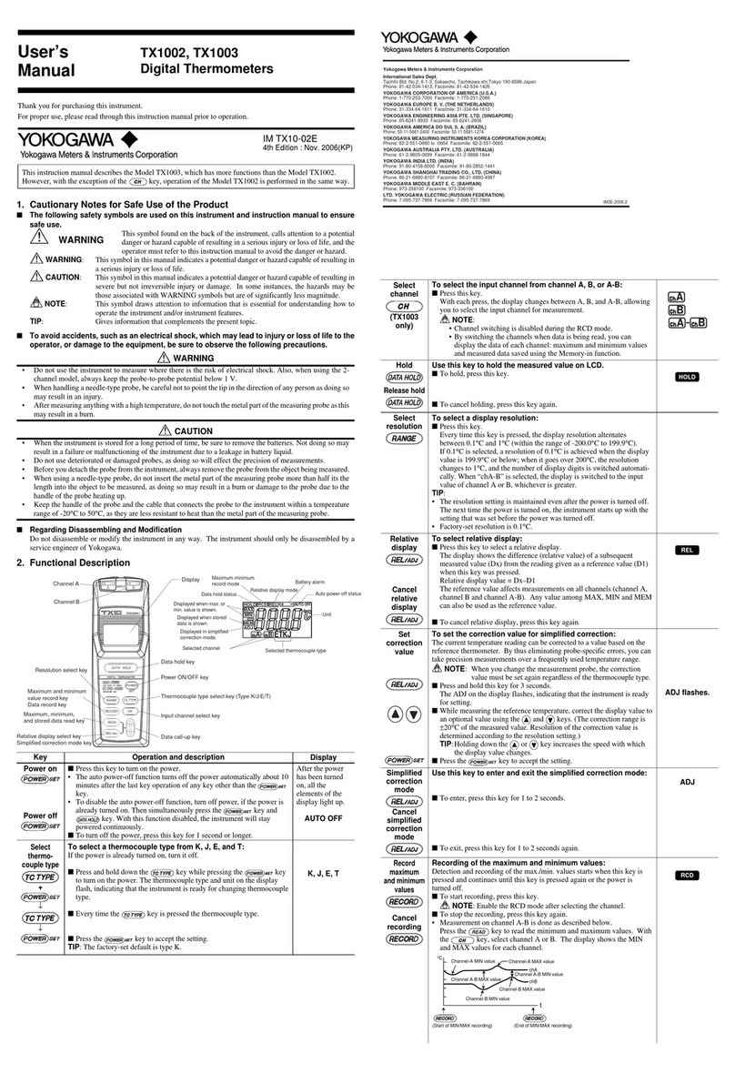
Recording of the maximum and minimum values:
Detection and recording of the max./min. values starts
when the RECORD key is pressed and continues until this key
is pressed again or the power is turned off.
Enable the RCD mode after selecting the channel.
■ To start recording, press the RECORD key.
■ To stop the recording, press the RECORD key again.
Measurement on channel A-B is done as described below.
Press the key to read the minimum and maximum values.
With the key, select channel A or B.
The display shows the MIN and MAX values for each channel.
chB
chA
Time (t)
Channel A-B MAX value
Channel-B MIN value
Channel-A MIN value
(Start of MIN/MAX recording) (End of MIN/MAX recording)
Channel A-B MIN value
Channel-B MAX value
Channel-A MAX value
Temperature
(°C)
To store data in memory
↓
↓
↓
To store data in internal memory
(maximum of 10 data items):
■ Press the DATA HOLD key to hold the measured value.
■ Press the RECORD key.
The display automatically shows the smallest memory number under
which no data has been recorded. At this point, the MEM symbol
turns on to indicate that the thermometer is in the “Memory-in” mode.
■ Select a memory number.
Use the [ ▲ ] and [ ▼ ] keys to select a desired memory number
under which you want to record data.
In this step, you can also check the existing data value.
Pressing the key while a memory number is being
displayed cancels the memory-in function
(returns to measurement mode).
TIP
TIP
■ Press the RECORD key to store the data.
The “HOLD” and “MEM” symbols indicate that the value recorded with
the memory-in function is being held and shown.
Press the key to return to normal measurement mode.
To read maximum and minimum values and stored data values
↓
To read maximum and minimum values and
stored data values from memory:
Channel switching and display when data is being read (TX1003 only):
■ Single channel (either channel A or B)
Using the key, display the channel used when the data was
measured. All of the maximum, minimum, and stored data values can
be displayed.
■ Two channels (channel A and B measurement)
• Pressing the key to select channel A or B shows the minimum
and maximum values, as well as the memory value, measured on that channel.
• Pressing the key to select ‘chA-chB’ displays the stored values of
the difference between channels A and B as well as the maximum or
minimum difference values.
• This data reading is disabled during thermocouple type selecting or
correction value setting.
• If you press the READ key when the REL mode is active, each of
the MIN, MAX and MEM values is shown as a relative value based
on the reference value (D1).
• The number of display digits of maximum and minimum/stored data
depends on the current resolution setting, not the number of
display digits at the time when the data was measured.
■ Select the memory number.
For stored data, select the memory
number using the [ ▲ ] or [ ▼ ] key.
After the memory number has been
displayed for a few seconds,
the value stored in
that memory is displayed.
■ When the READ key is pressed,
the display changes in the sequence
shown in the figure on the right.
MAX
MEM
MIN
chA
(or chB or chA-chB)
Memory number
selection
Source input channel
of the recorded data
Measured
value
Maximum
value
Stored
value
Minimum
value
Burnout indication
• When the probe is not connected to the input connector
(or the sensor opens), a burnout mark is displayed.
• For the 2-channel mode, the burnout mark is displayed
when the probe is not connected to the selected channel
(channel A and B, or channel A-B)
To clear the memory
TIP
↓
↓
To clear the recording memory:
■ Press the READ key to display stored data.
■ Select the memory number you wish to clear.
■ Press the RECORD key to clear the data.
To clear all the stored data in the memory at one time,
press and hold the RECORD key for 1 to 2 seconds.
Use the [ ▲ ] and [ ▼ ] keys to select a desired memory number.
This operation does not affect the maximum and minimum values.
8. Measurement
This instrument can connect any of the 4 types of thermocouples:
Type K, J, E, or T (it is set to Type K at shipment from the factory).
Use an omega-type connector corresponding to the TC type for the probe.
[ Procedure ]
(1) Load the batteries (see section "9. Battery Replacement").
(2) Press the key to turn on the power.
When the power has been turned on, all indications on the display light up
for about 2 seconds, then the measured value appears.
Burnout indication: - - - -
When the probe is not connected to the input connector,
a burnout mark is displayed.
(3) Check the thermocouple type.
If you wish to change the current setting, see "To select a thermocouple type" of
section "6.2 Functional Description."
(4) Select the input channel. (TX1003 only)
Press the key and select one channel from channel A, B, and A-B.
(see "To select the input channel.")
(5) Connect the probe to the input connector.
If you are using the 2-channel model (TX1003), connect the probe(s) to the channel(s)
you are using. (The measured value appears.)
(6) When you have nished measurement, turn off the power by
pressing the key.
• The power may be turned off by the auto power-off function during measurement.
In this case, press the key to restart the instrument and
continue measurement.
• If the power is turned off and then on again, the instrument restarts with
the same settings of the resolution (0.1°C or 1°C), input channel
(channel A, B or A-B) and thermocouple type (K, J, E or T) as before
it was turned off.
For other operations such as display hold, relative display, and maximum and minimum
record/readout, see section "7.2 Functional Description."
Key operation of this instrument is comparatively easy.
However, it is necessary to make sure that the instrument is not mistakenly set to
a state other than that intended. Note that, under normal measurement,
“HOLD,” “RCD,” “REL,” “MAX,” “MIN,” and “MEM” are not displayed.
9. Battery Replacement
• When inserting batteries, be careful not to mistake the polarity as this can damage
the instrument.
• When the instrument is to be stored for a long period of time, remove the batteries.
• Do not leave dead batteries in the instrument as doing so may result in a failure or
malfunction of the instrument due to a leakage in battery liquid.
• Both batteries should be replaced with new ones at the same time as replacing
only one of the batteries may result in the charge leaking from the new battery to the old.
• Lors de l'insertion des piles, faire en sorte de ne pas confondre de polarité, car cela
risquerait d'endommager l'instrument.
• Si l'instrument doit être stocké pendant une longue période, retirer les piles.
• Ne pas laisser de vieilles piles usagées dans l'instrument, car cela risquerait sinon
d'entraîner une défaillance ou un dysfonctionnement de l'instrument dû(e) à une fuite du
liquide des piles.
• Les deux piles doivent être remplacées par des nouvelles en même moment, car le fait de
n'en remplacer qu'une seule risque d'entraîner un transfert de charge de la nouvelle pile
vers l'ancienne.
When the batteries approach the end of their lives, the mark appears
on the display. If this mark is displayed, replace the batteries.
To replace the batteries:
(1) Remove the battery box cover from the back (rear) of the instrument.
Then replace the two AA alkaline dry batteries (LR6).
(2) Ret the cover to the battery box.
IM TX10-02-02EN <P2>

