York XA Series User manual

R-410A
XA SERIES W/SMART EQUIPMENT™
15/20 Ton
60 Hertz
5168274-BIM-I-1121
TABLE OF CONTENTS
General . . . . . . . . . . . . . . . . . . . . . . . . . . . . . . . . . . . . . . . . . . 2
Installation . . . . . . . . . . . . . . . . . . . . . . . . . . . . . . . . . . . . . . . . 5
Limitations . . . . . . . . . . . . . . . . . . . . . . . . . . . . . . . . . . . . 5
Location. . . . . . . . . . . . . . . . . . . . . . . . . . . . . . . . . . . . . . . . 7
Rigging And Handling . . . . . . . . . . . . . . . . . . . . . . . . . . . . . 7
Ductwork . . . . . . . . . . . . . . . . . . . . . . . . . . . . . . . . . . . . . . 13
Condensate Drain . . . . . . . . . . . . . . . . . . . . . . . . . . . . . . . 13
Compressors. . . . . . . . . . . . . . . . . . . . . . . . . . . . . . . . . . . 14
Filters . . . . . . . . . . . . . . . . . . . . . . . . . . . . . . . . . . . . . . . . 14
Power And Control Wiring. . . . . . . . . . . . . . . . . . . . . . . . . 14
Field Installed Electric Heat Accessories . . . . . . . . . . . . . 22
Options/Accessories . . . . . . . . . . . . . . . . . . . . . . . . . . . . . 22
Economizer Sequences . . . . . . . . . . . . . . . . . . . . . . . . . . 22
Dry Bulb Changeover . . . . . . . . . . . . . . . . . . . . . . . . . . . . 22
Single Enthalpy Changeover. . . . . . . . . . . . . . . . . . . . . . . 23
Dual Enthalpy Changeover . . . . . . . . . . . . . . . . . . . . . . . . 23
Auto. . . . . . . . . . . . . . . . . . . . . . . . . . . . . . . . . . . . . . . . . . 23
Free Cooling Operation. . . . . . . . . . . . . . . . . . . . . . . . . . . 23
Power Exhaust . . . . . . . . . . . . . . . . . . . . . . . . . . . . . . . . . 23
Setpoints . . . . . . . . . . . . . . . . . . . . . . . . . . . . . . . . . . . . . . 23
Inputs . . . . . . . . . . . . . . . . . . . . . . . . . . . . . . . . . . . . . . . . 23
Outputs . . . . . . . . . . . . . . . . . . . . . . . . . . . . . . . . . . . . . . . 23
Operation . . . . . . . . . . . . . . . . . . . . . . . . . . . . . . . . . . . . . 23
Field Installed BAS-Ready Economizer Power Exhaust
Damper Set Point Adjustment. . . . . . . . . . . . . . . . . . . . . . 28
Air Balance . . . . . . . . . . . . . . . . . . . . . . . . . . . . . . . . . . . . 34
Sequence Of Operation. . . . . . . . . . . . . . . . . . . . . . . . . . . . . 36
Cooling Sequence Of Operation . . . . . . . . . . . . . . . . . . . . 36
Cooling Operation Errors . . . . . . . . . . . . . . . . . . . . . . . . 36
Electric Heating Sequence Of Operations. . . . . . . . . . . . . 37
Defrost Termination . . . . . . . . . . . . . . . . . . . . . . . . . . . . 38
Interval between Defrosts. . . . . . . . . . . . . . . . . . . . . . . . 38
Forced Defrost . . . . . . . . . . . . . . . . . . . . . . . . . . . . . . . . 38
Electric Heat Operation Errors . . . . . . . . . . . . . . . . . . . . 38
Start-Up (Cooling) . . . . . . . . . . . . . . . . . . . . . . . . . . . . . . . . . 39
Charging The Unit . . . . . . . . . . . . . . . . . . . . . . . . . . . . . . . . . 40
Maintenance . . . . . . . . . . . . . . . . . . . . . . . . . . . . . . . . . . . . . 41
Normal Maintenance . . . . . . . . . . . . . . . . . . . . . . . . . . . . . 41
Filters . . . . . . . . . . . . . . . . . . . . . . . . . . . . . . . . . . . . . . . . 41
Motors . . . . . . . . . . . . . . . . . . . . . . . . . . . . . . . . . . . . . . . . 41
Blower Shaft Bearing . . . . . . . . . . . . . . . . . . . . . . . . . . . . 41
Outdoor Coil . . . . . . . . . . . . . . . . . . . . . . . . . . . . . . . . . . . 41
Start-Up Sheet. . . . . . . . . . . . . . . . . . . . . . . . . . . . . . . . . . . . 48
LIST OF TABLES
1 XA-15, XA-20 Unit Limitations. . . . . . . . . . . . . . . . . . . . . . 6
2 XA-15, XA-20 Unit Weight. . . . . . . . . . . . . . . . . . . . . . . . . 8
3 XA-15, XA-20 Unit Accessory Weights . . . . . . . . . . . . . . . 9
4 XA-15, XA-20 Unit Clearances . . . . . . . . . . . . . . . . . . . . 12
5 Control Wire Sizes. . . . . . . . . . . . . . . . . . . . . . . . . . . . . . 15
6 Electrical Data . . . . . . . . . . . . . . . . . . . . . . . . . . . . . . . . . 17
7 XA-15, XA-20 Physical Data . . . . . . . . . . . . . . . . . . . . . . 21
8 Electric Heat Minimum Supply Air . . . . . . . . . . . . . . . . . . 22
9 Smart Equipment™ Economizer Board Details . . . . . . . 25
10 Altitude/Temperature Correction Factors . . . . . . . . . . . . 30
11 Air Flow Performance - Side Duct Application . . . . . . . . 32
12 Air Flow Performance - Bottom Duct Application . . . . . . 33
13 RPM Selection . . . . . . . . . . . . . . . . . . . . . . . . . . . . . . . . 34
14 Indoor Blower Specifications . . . . . . . . . . . . . . . . . . . . . . 34
15 Power Exhaust Specifications . . . . . . . . . . . . . . . . . . . . . 34
16 Additional Static Resistance . . . . . . . . . . . . . . . . . . . . . . 35
17 Limit Control Setting . . . . . . . . . . . . . . . . . . . . . . . . . . . . 38
18 Electric Heat Anticipator Setpoint . . . . . . . . . . . . . . . . . . 39
19 Smart Equipment™ UCB Details . . . . . . . . . . . . . . . . . . 42
20 Cable for FC Buses and SA Buses in Order of Preference. . 47
LIST OF FIGURES
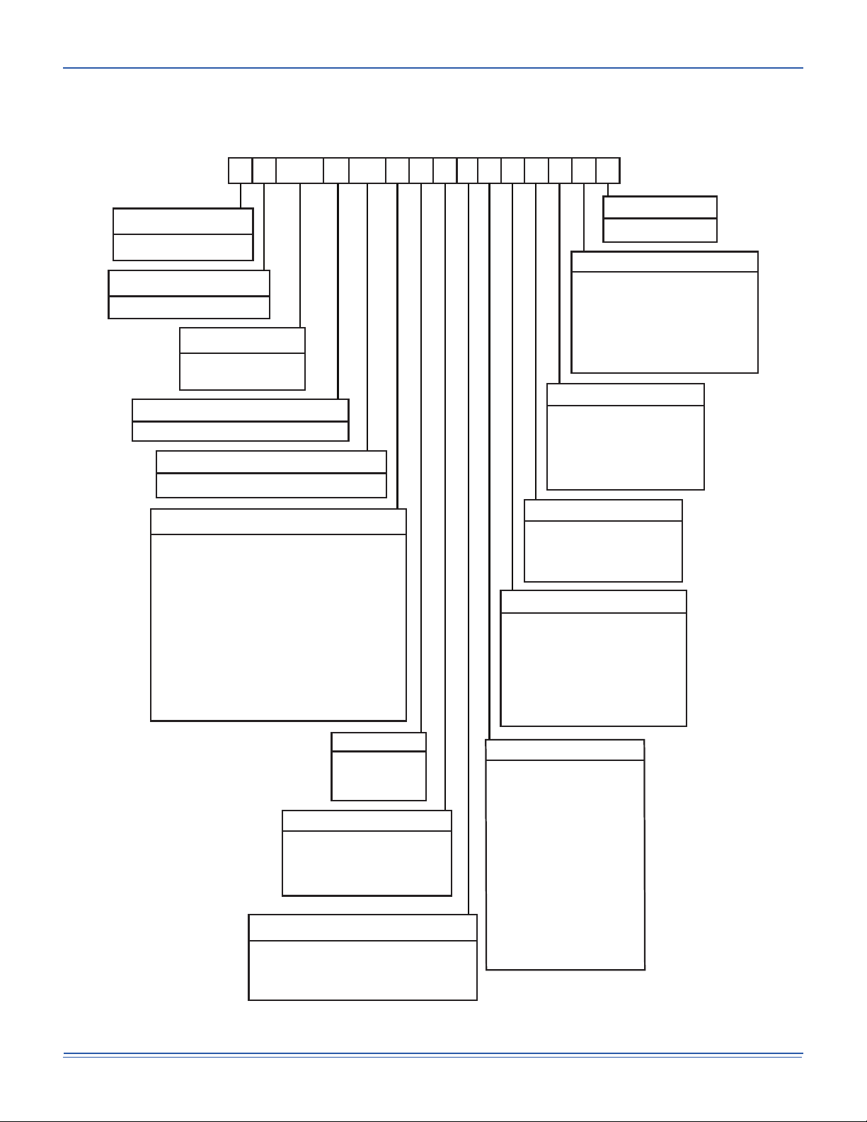
1 XA-20 Component Location . . . . . . . . . . . . . . . . . . . . . . . 6
2 XA-20 Unit 4 Point Load Weight . . . . . . . . . . . . . . . . . . . 8
3 XA-20 Unit 6 Point Load Weight . . . . . . . . . . . . . . . . . . . 8
4 XA-15 Unit 4 Point Load Weight . . . . . . . . . . . . . . . . . . . 8
5 XA-15 Unit 6 Point Load Weight . . . . . . . . . . . . . . . . . . . 8
6 Center of Gravity . . . . . . . . . . . . . . . . . . . . . . . . . . . . . . . 8
7 XA-20 Unit Dimensions Front View . . . . . . . . . . . . . . . . . 9
8 XA-15 Unit Dimensions Front View . . . . . . . . . . . . . . . . 10
9 XA-15, XA-20 Unit Dimensions Rear View . . . . . . . . . . 11
10 XA-15, XA-20 Unit Dimensions Rain Hood . . . . . . . . . . 12
11 XA-15, XA-20 Roof Curb . . . . . . . . . . . . . . . . . . . . . . . . 12
12 Fixed Outdoor Air Damper . . . . . . . . . . . . . . . . . . . . . . . 13
13 Condensate Drain . . . . . . . . . . . . . . . . . . . . . . . . . . . . . 13
14 Field Wiring Disconnect - Heat Pump Unit With/Without
Electric Heat . . . . . . . . . . . . . . . . . . . . . . . . . . . . . . . . . . 15
15 Typical Field Wiring 24 Volt Thermostat . . . . . . . . . . . . 16
16 SE-ECO1001-0 Economizer Controller . . . . . . . . . . . . . 25
17 Belt Adjustment . . . . . . . . . . . . . . . . . . . . . . . . . . . . . . . 29
18 Altitude/Temperature Correction Factors . . . . . . . . . . . . 30
19 Pressure Drop Across A Dry Indoor Coil Vs. Supply Air CFM
For All Unit Tonnages . . . . . . . . . . . . . . . . . . . . . . . . . . 34
20 XA-15 (15 Ton) Charging Chart . . . . . . . . . . . . . . . . . . . 40
21 XA-20 (20 Ton) Charging Chart . . . . . . . . . . . . . . . . . . . 40
22 Unit Control Board . . . . . . . . . . . . . . . . . . . . . . . . . . . . . 42

5168274-BIM-I-1121
2 Johnson Controls Ducted Systems
General
Ducted Systems Model XA units are single package Heat Pump
with electric heaters (Field Installed Accessory Only). Designed
for outdoor installation on a rooftop or slab.
The units are completely assembled on rigid, permanently
attached base rails. All piping, refrigerant charge, and electrical
wiring is factory installed and tested. The units require electric
power, duct connections and fixed outdoor air intake damper
(units without economizer option only) at the point of
installation.
The electric heater accessories have nickel-chrome elements
and utilize single point power connection.
Safety Considerations
This is a safety alert symbol. When you see this symbol on
labels or in manuals, be alert to the potential for personal injury.
Understand and pay particular attention the signal words
DANGER, WARNING or CAUTION.
DANGER indicates an imminently hazardous situation, which,
if not avoided, will result in death or serious injury.
WARNING indicates a potentially hazardous situation, which,
if not avoided, could result in death or serious injury.
CAUTION indicates a potentially hazardous situation, which, if
not avoided may result in minor or moderate injury. It is also
used to alert against unsafe practices and hazards involving
only property damage.
Due to system pressure, moving parts, and electrical
components, installation and servicing of air conditioning
equipment can be hazardous. Only qualified, trained service
personnel should install, repair, or service this equipment.
Untrained personnel can perform basic maintenance functions
of cleaning coils and filters and replacing filters.
Observe all precautions in the literature, labels, and tags
accompanying the equipment whenever working on air
conditioning equipment. Be sure to follow all other applicable
safety precautions and codes including ANSI Z223.1 or CSA-
B149.1- latest edition.
Wear safety glasses and work gloves. Use quenching cloth and
have a fire extinguisher available during brazing operations.
Inspection
As soon as a unit is received, it should be inspected for possible
damage during transit. If damage is evident, the extent of the
damage should be noted on the carrier’s freight bill. A separate
request for inspection by the carrier’s agent should be made in
writing.
Improper installation may create a condition where the
operation of the product could cause personal injury or
property damage. Improper installation, adjustment,
alteration, service or maintenance can cause injury or
property damage. Refer to this manual for assistance or
for additional information, consult a qualified contractor,
installer or service agency.
This product must be installed in strict compliance with
the installation instructions and any applicable local,
state and national codes including, but not limited to
building, electrical, and mechanical codes.
Before performing service or maintenance operations on
unit, turn off main power switch to unit. Electrical shock
could cause personal injury. Improper installation,
adjustment, alteration, service or maintenance can
cause injury or property damage. Refer to this manual.
For assistance or additional information consult a
qualified installer or service agency.
This system uses R-410A Refrigerant which operates at
higher pressures than R-22. No other refrigerant may be
used in this system. Gage sets, hoses, refrigerant
containers and recovery systems must be designed to
handle R-410A. If you are unsure, consult the equipment
manufacturer. Failure to use R-410A compatible servicing
equipment may result in property damage or injury.
This product must be installed in strict compliance with
the enclosed installation instructions and any applicable
local, state and national codes including, but not limited
to, building, electrical, and mechanical codes.

5168274-BIM-I-1121
Johnson Controls Ducted Systems 3
Reference
Additional information is available in the following reference
forms:
• Technical Guide - XA-15/XA-20, 5168281
• General Installation - XA-15/XA-20, 5168274
• Electric Heat Accessory Installation - 5128261
• Smart Equipment™ Control Quick Start Guide - 1136326
Renewal Parts
Contact your local Ducted Systems parts distribution center for
authorized replacement parts.
Approvals
Design certified by CSA as follows:
1. For use as a Heat Pump unit with supplemental electric
heat.
2. For outdoor installation only.
3. For installation on combustible material..
Improper installation may create a condition where the
operation of the product could cause personal injury or
property damage.
This system uses R-410A Refrigerant which operates at
higher pressures than R-22. No other refrigerant may be
used in this system.

5168274-BIM-I-1121
4 Johnson Controls Ducted Systems
Nomenclature
X A -15 CA2 A 1 A1A A 1
Product Category
X = HP, Single Pkg., R-410A
Product Generation
1 = First Generation
C = Cooling Only
Heat Type
Heat Capacity
Nominal Cooling Capacity
-15 = 15 Ton
-20 = 20 Ton
Product Identifier
A = Pkg HP Std Eff
Voltage
2 = 208/230-3-60
4 = 460-3-60
5 = 575-3-60
Additional Options
1 = STD Throwaway Filter
2 = 2" Pleated Filters (Merv 8)
3 = 4" Pleated Filters (Merv 13)
4 = Coil Guard (CG), STD Filter
5 = 2" Pleated Filter,CG
6 = 4" Pleated Filter,CG
1 = No Service Options
2 = DSC (Disconnect Switch)
5 = DSC, NCO (Non-powered Convenience Outlet)
6 = DSC, PCO (Powered Convenience Outlet)
Refrigeration
A = Standard Refrigeration
B = ECC (E-Coat Cond Coil)
C = EEC (E-Coat Evap Coil)
F = ECC,EEC
Service Options
A = Stand Alone Smart Equipment™
C = BACnet MSTP,Mdbs,N2 COM Card
D = CPC Control, DFS, APS
G = Novar UCM Ctrl, DFS, APS
H = Hnywll Excel 10 CTRL,DFS,APS
M = Verasys Single Zone
N = Verasys Change Over Bypass
P = Verasys VAV
Controls Option
15 & 20 Ton Model Number Nomenclature
00
00 = Cooling Only
A
B = Standard Static
D = High Static
E = VFD/VAV Std Static
G = VFD/VAV High Static
H = VFD/VAV w/Bypass Std Static
K = VFD/VAV w/Bypass High Static
L = VFD/VAV Customer Std Static
N = VFD/VAV Customer High Static
P = VFD IntelliSpeed Std Static
R = VFD IntelliSpeed High Static
S = VFD w/Byp IntelliSp Std Static
U = VFD w/Byp IntelliSp Hi Static
V = VFD Cust IntelliSp Std Static
X = VFD Cust IntelliSp Hi Static
A = No Economizer
B = Economizer w/Barometric RLF
1
C = Economizer w/o Barometric RLF
D = Economizer w/Power EXH
1
Outdoor Air Option
Note: 1. Available Downflow Only
Blower Option
A = Std Cabinet
B = HFD (Hinged FLTR/Toolless DR)
C = HCD (Hinged & Toolless ACS DR)
E = SSD (SST Drain Pan)
F = SSD,HFD
G = SSD,HCD
H = SSD,DBW/HCD
A = No Sensors
B = PHM (Phase Monitor)
C = DFS (Dirty Filter Switch)
D = SAD (Supply Air Smoke DET)
E = RSD (Return Air Smoke DET)
F = PHM,DFS
G = PHM,SAD
H = PHM,RSD
J = DFS,SAD
K = DFS,RSD
L = SAD,RSD
M = PHM,DFS,SAD
N = PHM,DFS,RSD
P = PHM,SAD,RSD
Q = DFS,SAD,RSD
R = PHM,DFS,SAD,RSD
Sensors
Cabinet Options

5168274-BIM-I-1121
Johnson Controls Ducted Systems 5
Installation
Installation Safety Information
Read these instructions before continuing this appliance
installation. This is an outdoor combination heating and cooling
unit. The installer must assure that these instructions are made
available to the consumer and with instructions to retain them
for future reference.
1. This equipment is not to be used for temporary heating of
buildings or structures under construction.
2. If a factory option convenience outlet is installed, the
weatherproof outlet cover must be field installed. The cover
shall be located in the unit control box. To install the cover,
remove the shipping label covering the convenience outlet,
follow the instructions on the back of the weatherproof
cover box, and attach the cover to the unit using the (4)
screws provided.
Limitations
These units must be installed in accordance with the following:
In U.S.A.:
1. National Electrical Code, ANSI/NFPA No. 70 - Latest
Edition
2. Local building codes, and
3. Local electric utility requirements
In Canada:
1. Canadian Electrical Code, CSA C22.1
2. Installation Codes, CSA - B149.1.
3. Local plumbing and waste water codes, and
4. Other applicable local codes.
Refer to unit application data found in this document.
If components are to be added to a unit to meet local codes,
they are to be installed at the dealer’s and/or customer’s
expense.
Size of unit for proposed installation should be based on heat
loss/heat gain calculation made according to the methods of Air
Conditioning Contractors of America (ACCA).
This furnace is not to be used for temporary heating of buildings
or structures under construction.
208/230-3-60 units with factory installed Powered
Convenience Outlet Option are wired for 230v power
supply. Change tap on transformer for 208-3-60. See
unit wiring diagram.
The Smart Equipment™ control board used in this
product will effectively operate the cooling system down
to 0°F when this product is applied in a comfort cooling
application for people. An economizer is typically
included in this type of application. When applying this
product for process cooling applications (computer
rooms, switchgear, etc.), call the applications
department for Ducted Systems @ 1-877-874-SERV for
guidance. Additional accessories may be needed for
stable operation at temperatures below 30°F.

5168274-BIM-I-1121
6 Johnson Controls Ducted Systems
Figure 1: XA-20 Component Location
Table 1: XA-15, XA-20 Unit Limitations
Size
(Tons) Unit Voltage SCCR (kVA)
Unit Limitations
Applied Voltage Outdoor DB Temp
Min Max Max (°F)
-15
(15)
208/230-3-60 5 187 252 125
460-3-60 5 432 504 125
575-3-60 5 540 630 125
-20
(20)
208/230-3-60 5 187 252 125
460-3-60 5 432 504 125
575-3-60 5 540 630 125
Smart Equipment™ Control Board
110 Volt Convenience
Outlet (“Powered” or
“Non-Powered” Optional)
Disconnect Location
(Optional Disconnect Switch)
Bottom Power and
Control Wiring Entry
Electric Heater Location
(Electric Heat Offered as a Field-Installed Accessory Only)
Belt Drive
Blower Motor
14 Gauge
Base Rails
with Lifting Holes
1” NPT
Condensate Drain
Thermal
Expansion
Valve
Copper Tube/
Aluminum Fin
Evaporator
Coils
2” Disposable Filters
(4” Filters Optional)
Slide In/ Plug In
Internal Economizer
(Optional)

5168274-BIM-I-1121
Johnson Controls Ducted Systems 7
Location
Use the following guidelines to select a suitable location for
these units:
1. Unit is designed for outdoor installation only.
2. Condenser coils must have an unlimited supply of air.
Where a choice of location is possible, position the unit on
either north or east side of building.
3. Suitable for mounting on roof curb.
4. For ground level installation, use a level concrete slab with
a minimum thickness of 4 inches. The length and width
should be at least 6 inches greater than the unit base rails.
Do not tie slab to the building foundation.
5. Roof structures must be able to support the weight of the
unit and its options/accessories. Unit must be installed on a
solid, level roof curb or appropriate angle iron frame.
6. Maintain level tolerance to 1/2” across the entire width and
length of unit.
Clearances
All units require particular clearances for proper operation and
service. Refer to Table 4 for clearances required for
combustible construction, servicing, and proper unit operation.
Rigging And Handling
Exercise care when moving the unit. Do not remove any
packaging until the unit is near the place of installation. Rig the
unit by attaching chain or cable slings to the lifting holes
provided in the base rails. Spreader bars, whose length
exceeds the largest dimension across the unit, MUST be used
across the top of the unit.
Units may be moved or lifted with a forklift, from the side only,
providing an accessory skid is used.
LENGTH OF FORKS MUST BE A MINIMUM OF 90 INCHES.
Do not permit overhanging structures or shrubs to
obstruct condenser air discharge outlet, or vent outlets.
If a unit is to be installed on a roof curb other than a
Ducted Systems roof curb, gasketing must be applied to
all surfaces that come in contact with the unit underside.
Before lifting, make sure the unit weight is distributed
equally on the rigging cables so it will lift evenly.
All panels must be secured in place when the unit is
lifted.
The condenser coils should be protected from rigging
cable damage with plywood or other suitable material.

5168274-BIM-I-1121
8 Johnson Controls Ducted Systems
Figure 2: XA-20 Unit 4 Point Load Weight Figure 3: XA-20 Unit 6 Point Load Weight
Figure 4: XA-15 Unit 4 Point Load Weight Figure 5: XA-15 Unit 6 Point Load Weight
Figure 6: Center of Gravity
A
D
B
C
A
D
E
C
F
B
A
B
C
D
FRONT
A
C
D
F
B
E
FRONT
Table 2: XA-15, XA-20 Unit Weight
Size
(Tons) Model Weight (lbs.) Center of Gravity 4 Point Load Location (lbs.) 6 Point Load Location (lbs.)
Shipping Operating X Y A B C D A B C D E F
-15 (15) XA 2145 2140 77.1 45 454 592 619 475 290 344 413 431 359 303
-20 (20) XA 2655 2650 88.8 46 462 863 863 462 280 405 640 640 405 280
XY
LEFT FRONT

5168274-BIM-I-1121
Johnson Controls Ducted Systems 9
Figure 7: XA-20 Unit Dimensions Front View
NOTE: All entry holes should be field sealed to prevent rain water
entry into the building.
Table 3: XA-15, XA-20 Unit Accessory Weights
Unit Accessory Weight (lbs.)
Shipping Operating
Economizer 165 160
Power Exhaust 90 85
Electric Heat1
1. Weight given is for the maximum heater size available
(72KW).
40 40
Double Wall2
2. Available on XA-20 only.
260 260
Motorized Damper 150 150
Barometric Damper 50 45
Econ./Motorized Damper Rain Hood 60 55
Econ./Power Exhaust Rain Hood 95 90
Wood Skid 220 220
Roof Curb 190 185
Utilities Entry
Hole Opening Size
Diameter Used For
A1-1/8” KO Control Wiring Front
3/4” NPS (Fem.) Bottom
B3-5/8” KO Power Wiring Front
3” NPS (Fem.) Bottom
6-7/8
(A) CONTROL WIRING
ENTRY
COIL
GUARD
KIT
CONDENSER
COILS
(B) POWER
WIRING ENTRY
5
43-3/4
9-3/4
35
5-7/8
136-1/4
DOT PLUG
(For pressure
drop reading)
BLOWER
COMPARTMENT
ACCESS
(Auxillary)
CONTROL BOX
ACCESS
BLOWER MOTOR
ACCESS BLOWER
ACCESS
52-5/8
180-19/32 COMPRESSOR ACCESS
DISCONNECT
SWITCH
LOCATION
ECONOMIZER / MOTORIZED DAMPER
FIXED OUTDOOR INTAKE AIR AND
POWER EXHAUST RAIN HOODS
92
35-1/4
33
2-3/4 3-3/4
(B) POWER WIRING
ENTRY
BOTTOM SUPPLY
AND RETURN
AIR OPENINGS
(See Note)
(A) CONTROL WIRING
ENTRY
21-1/2
UNIT BASE RAILS
Shown separately to illustrate
Bottom Duct openings. Power
location.
RETURN
AIR
NOTE:
For curb mounted units, refer to the curb hanger
dimensions of the curb for proper size of the
supply and return air duct connections.
12-1/2
9-1/4
8-1/8
9-3/4
SUPPLY
AIR
14-3/4
OPTIONAL
ELECTRIC HEAT
ACCESS

5168274-BIM-I-1121
10 Johnson Controls Ducted Systems
Figure 8: XA-15 Unit Dimensions Front View
NOTE: All entry holes should be field sealed to prevent rain
water entry into the building.
Utilities Entry
Hole Opening Size
Diameter Used For
A1-1/8” KO Control Wiring Front
3/4” NPS (Fem.) Bottom
B3-5/8” KO Power Wiring Front
3” NPS (Fem.) Bottom
RETURN
AIR
SUPPLY
AIR
BOTTOM SUPPLY
AND RETURN
AIR OPENINGS
(See Note)
(B)
POWER WIRING
ENTRY
(A)
CONTROL WIRING
ENTRY
NOTE:
For curb mounted units, refer to the curb hanger
dimensions of the curb for the proper size of the
supply and return air duct connections.
UNIT BASE WITH RAILS
Shown separately to illustrate
Bottom Duct openings and Power
Connection locations
12-1/2"
9-1/4"
8-1/8"
9-3/4"
3-3/4"
(B)
POWER WIRING
ENTRY
(A)
CONTROL WIRING
ENTRY
92"
CONDENSER
COILS
OPTIONAL COIL
GUARD KIT
52-5/8"
COMPRESSOR
ACCESS
(See detail "X")
ECONOMIZER / MOTORIZED DAMPER,
FIXED OUTDOOR INTAKE AIR AND
POWER EXHAUST RAIN HOODS
(See detail "Y")
FIELD-SUPPLIED
DISCONNECT SWITCH
LOCATION
BLOWER
ACCESS
BLOWER MOTOR
ACCESS
BLOWER
COMPARTMENT
ACCESS
(Auxiliary)
DOT PLUG
(For pressure
Drop Reading)
FRONT
VIEW ELECTRIC HEAT
ACCESS
CONTROL BOX
ACCESS
136-1/4"
21"
5"
9-3/4"
11-1/2"
2-3/4" 21-1/2"
33"
35"
5-7/8"
35-1/4"
RETURN AIR
SUPPLY AIR
OUTDOOR A IR
OUTDOOR A IR
(Economizer)
OPTIONAL

5168274-BIM-I-1121
Johnson Controls Ducted Systems 11
Figure 9: XA-15, XA-20 Unit Dimensions Rear View
NOTE: Units are shipped with the bottom duct openings
covered. An accessory flange kit is available for
connecting side ducts.
For bottom duct applications:
1. Remove the side panels from the supply and return air
compartments to gain access to the bottom supply and
return air duct covers.
2. Remove and discard the bottom duct covers. Duct
openings are closed with sheet metal covers except when
the unit includes a power exhaust option. The covering
consists of a heavy black paper composition.
3. Replace the side supply and return air compartment
panels.
For side duct applications:
1. Replace the side panels on the supply and return air
compartments with the accessory flange kit panels.
2. Connect ductwork to the flanges on those panels.
SUPPLY
AIR
RETURN
AIR
OUTDOOR
AIR
5-1/8"
18-5/8"
27-3/4"
39-5/8"
40-1/2"
OUTDOOR AIR
COMPARTMENT
ACCESS
FILTER
ACCESS
1" NPT FEMALE
COND. DRAIN
CONNECTION
DOT PLUG
(For pressure
drop reading)
EVAPORATOR
SECTION
40-3/8"
COMPRESSOR
ACCESS
SUPPLY AIR
ACCESS
RETURN AIR
ACCESS
REAR
VIEW
Dimensions listed are for side
duct flange openings; see
Field Accessories for Side
Duct Flange Kit.

5168274-BIM-I-1121
12 Johnson Controls Ducted Systems
Figure 10: XA-15, XA-20 Unit Dimensions Rain Hood
Note: Units and ductwork are approved for zero clearance to combustible material when equipped with electric
heaters.
Figure 11: XA-15, XA-20 Roof Curb
Table 4: XA-15, XA-20 Unit Clearances
Direction Distance (in.) Direction Distance (in.)
Top1
1. Units must be installed outdoors. Over hanging structure or shrubs should not obscure condenser air discharge outlet.
72 With 36 Maximum Horizontal Overhang
(For Condenser Air Discharge) Right 36
Front 36 Bottom2
2. Units may be installed on combustable floors made from wood or class A, B or C roof covering materials.
0
Rear 24 (W/O Economizer) Left 24 (W/O Economizer)
49 (W/Economizer) 36 (W/Economizer)3
3. If economizer is factory installed, the unassembled rain hood must be removed from its ride along position in front of the
evaporator coil, or in the outdoor air compartment, prior to final installation.
LH View
92”28-3/16”
36-5/8”
5”
16-1/8”
Rear View
Supply Air
Compartment
Power Exhaust
Rain Hood
(on Return
Air Compartment)
Economizer Motorized
Damper Rain Hood
(on Outdoor
Air Compartment) Economizer/Motorized Damper
and Power Exhaust Rain Hood
Fixed
Outdoor Air
Intake Hood
(Located on
Return Air
Compartment) 1” Condensate
Drain (Must be
Trapped)
Detail “Y”
Unit with Rain Hoods
25-1/4"

5168274-BIM-I-1121
Johnson Controls Ducted Systems 13
Ductwork
Ductwork should be designed and sized according to the
methods in Manual D of the Air Conditioning Contractors of
America (ACCA) or as recommended by any other recognized
authority such as ASHRAE or SMACNA.
A closed return duct system should be used. This will not
preclude use of economizers or outdoor fresh air intake. The
supply and return air duct connections at the unit should be
made with flexible joints to minimize noise.
The supply and return air duct systems should be designed for
the CFM and static pressure requirements of the job. They
should NOT be sized to match the dimensions of the duct
connections on the unit.
Refer to Figures 7 and 8 for bottom air duct openings. Refer to
Figure 9 for side air duct openings.
NOTE: It is recommended that, in Canada, the outlet duct be
provided with a removable access panel. It is
recommended that this opening be accessible when
the unit is installed in service, and of a size such that
smoke or reflected light may be observed inside the
casing to indicate the presence of leaks in the heat
exchanger. The cover should be attached in a
manner adequate to prevent leakage.
Fixed Outdoor Air Intake Damper
This damper is shipped inside the return air compartment. It is
completely assembled and ready for installation. A damper
baffle inside of the hood is adjustable to provide variable
amounts of outdoor air intake on units that are not provided with
an economizer or a motorized damper option. Refer to the
Fixed Outdoor Damper Figure 12.
Gasketing and mounting screws are provided in a parts bag
attached to the hood assembly. Apply gasketing to the three
flange surfaces on the hood prior to installing the hood. Extend
gasketing 1/4 inch beyond the top and bottom of the two side
flanges to insure adequate sealing.
Adjusting the damper to the desired air flow may be done
before mounting the hood into position or after installation by
removing the front hood panel or the screen on the bottom of
the hood. Damper baffle in position 1 will allow approximately
10% outdoor air flow, position 2 approximately 15% and, to
allow approximately 25%, remove the damper baffle.
On units with bottom return air application install the damper
assembly over the opening in the side return air access panel.
Remove and discard the opening cover and the covering over
the hood mounting holes (used for shipping) before installing.
Secure with the screws provided.
On units with side return air applications, install the damper
assembly on the return air ductwork as close to the unit as
possible. Cut an opening 16 inches high by 18 inches wide in the
ductwork to accommodate the damper. Using the holes in the
hood flanges as a template, drill 9/64 inch diameter (#26 drill)
holes into the ductwork and secure with the screws provided.
Figure 12: Fixed Outdoor Air Damper
Condensate Drain
Plumbing must conform to local codes. Use a sealing compound
on male pipe threads. Install a condensate drain line from the
one-inch NPT female connection on the unit to an open drain.
NOTE: The condensate drain operates in a negative pressure
in the cabinet. The condensate drain line MUST be
trapped to provide proper drainage. See Figure 13.
Figure 13: Condensate Drain
If outdoor air intake will not be required on units with
bottom return air applications, the damper assembly
should still be mounted on the side return air access
panel, per the instructions above, to insure moisture is
not drawn into the unit during operation. The covering
over the mounting holes only need be removed. Do not
remove the opening cover.
*
Side Supply
Air Access
Panel
Damper
Baffle
Hood
Screen
* Gasketed
Flange Rear View
Side Return Air
Access Panel
Outdoor Air
Opening Cover
2
1
Base
Pan
Base
Rails
Drain
Plug
2”
3” Min.
Unit Condensate
Connection

5168274-BIM-I-1121
14 Johnson Controls Ducted Systems
Compressors
The scroll compressor used in this product is specifically
designed to operate with R-410A Refrigerant and cannot be
interchanged.
The compressor also uses a polyolester (POE oil), Mobil 3MA
POE. This oil is extremely hygroscopic, meaning it absorbs water
readily. POE oil can absorb 15 times as much water as other oils
designed for HCFC and CFC refrigerants. Take all necessary
precautions to avoid exposure of the oil to the atmosphere.
POE (polyolester) compressor lubricants are known to cause
long term damage to some synthetic roofing materials.
Procedures which risk oil leakage include, but are not limited to,
compressor replacement, repairing refrigerant leaks, replacing
refrigerant components such as filter drier, pressure switch,
metering device or coil.
Units are shipped with compressor mountings which are
factory-adjusted and ready for operation.
Filters
Two-inch filters are supplied with each unit. For XA-20 models,
the filter rack can be easily modified to accommodate four inch
filters. Filters must always be installed ahead of the evaporator
coil and must be kept clean or replaced with same size and
type. Dirty filters will reduce the capacity of the unit and will
result in frosted coils or safety shutdown. Minimum filter area
and required sizes are shown in Physical Data Table 7.
Power And Control Wiring
Field wiring to the unit, fuses, and disconnects must conform to
provisions of National Electrical Code (NEC), ANSI/NFPA No.
70 – Latest Edition (in U.S.A.), current Canadian Electrical
Code C221, and/or local ordinances. The unit must be
electrically grounded in accordance with NEC and CEC as
specified above and/or local codes.
Voltage tolerances which must be maintained at the
compressor terminals during starting and running conditions are
indicated on the unit Rating Plate and Table 1.
The internal wiring harnesses furnished with this unit are an
integral part of the design certified unit. Field alteration to
comply with electrical codes should not be required. If any of
the wire supplied with the unit must be replaced, replacement
wire must be of the type shown on the wiring diagram and the
same minimum gauge as the replaced wire.
A disconnect must be utilized for these units. Factory installed
disconnects are available. If installing a disconnect (field
supplied or Ducted Systems supplied accessory), refer to
Figure 1 for the recommended mounting location.
NOTE: Since not all local codes allow the mounting of a
disconnect on the unit, please confirm compliance with
local code before mounting a disconnect on the unit.
Electrical line must be sized properly to carry the load. USE
COPPER CONDUCTORS ONLY. Each unit must be wired with
a separate branch circuit fed directly from the meter panel and
properly fused.
This system uses R-410A Refrigerant which operates at
higher pressures than R-22. No other refrigerant may be
used in this system.
Do not leave the system open to the atmosphere. Unit
damage could occur due to moisture being absorbed by
the POE oil in the system. This type of oil is highly
susceptible to moisture absorption
Exposure, even if immediately cleaned up, may cause
embrittlement (leading to cracking) to occur in one year
or more. When performing any service that may risk
exposure of compressor oil to the roof, take precautions
to protect roofing.
Do not loosen compressor mounting bolts.
Make sure that panel latches are properly positioned on
the unit to maintain an airtight seal.
208/230-3-60 unit control transformers are factory wired
for 230v power supply. Change tap on transformer for
208-3-60 operation. See unit wiring diagram.
Avoid damage to internal components if drilling holes for
disconnect mounting.

5168274-BIM-I-1121
Johnson Controls Ducted Systems 15
Refer to Figures 14 and 15 for typical field wiring and to the
appropriate unit wiring diagram mounted inside control doors
for control circuit and power wiring information.
Power Wiring Detail
Units are factory wired for the voltage shown on the unit
nameplate. Refer to Electrical Data Table 6 to size power
wiring, fuses, and disconnect switch.
Power wiring is brought into the unit through the side of the unit
or the basepan inside the curb.
Figure 14: Field Wiring Disconnect - Heat Pump Unit With/Without Electric Heat
Thermostat Wiring
The thermostat should be located on an inside wall approximately
56 inch above the floor where it will not be subject to drafts, sun
exposure or heat from electrical fixtures or appliances. Follow the
manufacturer's instructions enclosed with thermostat for general
installation procedure. Color-coded, insulated wires should be
used to connect the thermostat to the unit. Refer to Table 5 for
control wire sizing and maximum length.
Space Sensor
The space sensor, if used, should be located on an inside wall
approximately 56 inches above the floor where it will not be
subject to drafts, sun exposure or heat from electrical fixtures or
appliances. Follow manufacturer's instructions enclosed with
sensor for general installation procedure.
When connecting electrical power and control wiring to
the unit, water-proof connectors must be used so that
water or moisture cannot be drawn into the unit during
normal operation. The above water-proofing conditions
will also apply when installing a field supplied disconnect
switch.
THREE
PHASE
POWER
SUPPLY
FACTORY OR FIELD
SUPPLIED DISCONNECT
GROUND
LUG
TERMINAL BLOCK TB1
Table 5: Control Wire Sizes
Wire Size Maximum Length1
1. From the unit to the thermostat and back to the unit.
18 AWG 150 Feet

5168274-BIM-I-1121
16 Johnson Controls Ducted Systems
Figure 15: Typical Field Wiring 24 Volt Thermostat
OCC
C
RC
G
Y2
Y1
W2
W1
X
R
THERMOSTAT
TERMINALS
CONTROL
TERMINAL
BLOCK
TERMINALS ON A
LIMITED NUMBER
OF THERMOSTATS
1
4
3
1
2
4
Second stageŚĞĂƟŶŐŶot required on single stage heĂƟŶg units.
Jumper is required if there is no Smoke Detector circuit.
Jumper is required for any coŵďŝŶĂƟŽŶ of R, RC, or RH.
5
5
OCC is an output from the thermostat to indicate the Occupied ĐŽŶĚŝƟon.
X is an input to the thermostat to display Error Status condiƟons.
3
W2
Y1
G
OCC
Y2
X
R
SD-24
C
W1
2
24V
C
24 VAC
Class 2
SD-24 Jumper Located on Harness
Smoke
Detector
SD-R
24V Output
R
(If No Smoke Detector) (If Smoke Detector Is Used)
R~Occ Jumper:
Smart Equipment Control boards come from the
factory with a jumper wire between R and OCC
terminals on the thermostat terminal strip. Failure
to remove this jumper will place the unit into the
Occupied mode no matter what the occupancy
demand is from the thermostat or EMS system.
To allow Thermostat or EMS control of the
Occupied mode for the unit, this jumper must be
removed during commissioning.
208/230-3-60 unit control transformers are factory wired
for 230v power supply. Change tap on transformer for
208-3-60 operation. See unit wiring diagram.

5168274-BIM-I-1121
Johnson Controls Ducted Systems 17
Table 6: Electrical Data
XA-15, XA-20 - Standard Drive Without Powered Convenience Outlet
Size
(Tons) Volt
Compressors
(each)
OD Fan
Motors
(each)
Supply
Blower
Motor
Pwr
Conv
Outlet
Electric Heat
(Field Installed Accessory Only) MCA1
(Amps)
Max Fuse2/
Breaker3
Size
(Amps)
RLA LRA MCC FLA FLA FLA Model kW Stages Amps
-15
(15)
208-3-60 25 164 39 4.1 13.5 0
NONE - - - 78 100
E18 13.5 1 37.5 124.8 125
E36 27 2 74.9 124.8 125
E54 40.6 2 112.7 157.7 175
E72 54.1 2 150.2 171.6 200
230-3-60 25 164 39 3.9 13 0
NONE - - - 77.1 100
E18 18 1 43.3 131.2 150
E36 36 2 86.6 131.2 150
E54 54 2 129.9 146.2 175
E72 72 2 173.2 189.5 225
460-3-60 12.2 100 19 2.15 6.5 0
NONE - - - 38.3 50
E18 18 1 21.7 65.3 70
E36 36 2 43.3 65.3 70
E54 54 2 65 73.1 80
E72 72 2 86.6 94.7 110
575-3-60 9 78 14 1.6 5.2 0
NONE - - - 28.7 35
E18 18 1 17.3 50.3 60
E36 36 2 34.6 50.3 60
E54 54 2 52 58.5 70
E72 72 2 69.3 75.8 90
-20
(20)
208-3-60 34.3 239 52 3.4 20
NONE - - - 110.8 125
E18 13.5 1 37.5 157.7 175
E36 27 2 74.9 157.7 175
E54 40.6 2 112.7 165.9 175
E72 54.1 2 150.2 204.4 225
230-3-60 3.4 19.4
NONE - - - 110.2 125
E18 18 1 43.3 164.3 175
E36 36 2 86.6 164.3 175
E54 54 2 129.9 164.3 175
E72 72 2 173.2 218.5 225
460-3-60 17.9 125 28 1.8 9.7
NONE - - - 57.2 70
E18 18 1 21.7 84.3 90
E36 36 2 43.3 84.3 90
E54 54 2 65 84.3 90
E72 72 2 86.6 111.3 125
575-3-60 12.8 80 20 1.4 7.8
NONE - - - 42.2 50
E18 18 1 17.3 63.8 70
E36 36 2 34.6 63.8 70
E54 54 2 52 63.8 70
E72 72 2 69.3 85.5 90
1. Minimum Circuit Ampacity.
2. Dual Element, Time Delay Type.
3. HACR type per NEC.

5168274-BIM-I-1121
18 Johnson Controls Ducted Systems
XA-15, XA-20 - Standard Drive With Powered Convenience Outlet
Size
(Tons) Volt
Compressors
(each)
OD Fan
Motors
(each)
Supply
Blower
Motor
Pwr
Conv
Outlet
Electric Heat
(Field Installed Accessory Only) MCA1
(Amps)
1. Minimum Circuit Ampacity.
Max Fuse2/
Breaker3
Size
(Amps)
2. Dual Element, Time Delay Type.
3. HACR type per NEC.
RLA LRA MCC FLA FLA FLA Model kW Stages Amps
-15
(15)
208-3-60 25 164 39 4.1 13.5 10
NONE - - - 88 110
E18 13.5 1 37.5 134.8 150
E36 27 2 74.9 134.8 150
E54 40.6 2 112.7 170.2 175
E72 54.1 2 150.2 181.6 200
230-3-60 25 164 39 3.9 13 10
NONE - - - 87.1 110
E18 18 1 43.3 141.2 150
E36 36 2 86.6 141.2 150
E54 54 2 129.9 158.7 175
E72 72 2 173.2 202 225
460-3-60 12.2 100 19 2.15 6.5 5
NONE - - - 43.3 50
E18 18 1 21.7 70.3 80
E36 36 2 43.3 70.3 80
E54 54 2 65 79.3 90
E72 72 2 86.6 101 110
575-3-60 9 78 14 1.6 5.2 4
NONE - - - 32.7 40
E18 18 1 17.3 54.3 60
E36 36 2 34.6 54.8 60
E54 54 2 52 63.5 70
E72 72 2 69.3 80.8 90
-20
(20)
208-3-60 34.3 239 52 3.4 20 20
NONE - - - 120.8 150
E18 13.5 1 37.5 167.7 175
E36 27 2 74.9 167.7 175
E54 40.6 2 112.7 178.4 200
E72 54.1 2 150.2 214.4 225
230-3-60 3.4 19.4 20
NONE - - - 120.2 150
E18 18 1 43.3 174.3 175
E36 36 2 86.6 174.3 175
E54 54 2 129.9 174.3 175
E72 72 2 173.2 228.5 250
460-3-60 17.9 125 28 1.8 9.7 20
NONE - - - 62.2 80
E18 18 1 21.7 89.3 100
E36 36 2 43.3 89.3 100
E54 54 2 65 89.3 100
E72 72 2 86.6 116.3 125
575-3-60 12.8 80 20 1.4 7.8 20
NONE - - - 46.2 50
E18 18 1 17.3 67.8 70
E36 36 2 34.6 67.8 70
E54 54 2 52 67.8 70
E72 72 2 69.3 89.5 90

5168274-BIM-I-1121
Johnson Controls Ducted Systems 19
XA-15, XA-20 - High Static Drive Without Powered Convenience Outlet
Size
(Tons) Volt
Compressors
(each)
OD Fan
Motors
(each)
Supply
Blower
Motor
Pwr
Conv
Outlet
Electric Heat
(Field Installed Accessory Only) MCA1
(Amps)
1. Minimum Circuit Ampacity.
Max Fuse2/
Breaker3
Size
(Amps)
2. Dual Element, Time Delay Type.
3. HACR type per NEC.
RLA LRA MCC FLA FLA FLA Model kW Stages Amps
-15
(15)
208-3-60 25 164 39 4.1 20 0
NONE - - - 84.5 100
E18 13.5 1 37.5 131.3 150
E36 27 2 74.9 131.3 150
E54 40.6 2 112.7 165.9 175
E72 54.1 2 150.2 178.1 200
230-3-60 25 164 39 3.9 19.4 0
NONE - - - 83.5 100
E18 18 1 43.3 137.6 150
E36 36 2 86.6 137.6 150
E54 54 2 129.9 154.2 175
E72 72 2 173.2 197.5 225
460-3-60 12.2 100 19 2.15 9.7 0
NONE - - - 41.5 50
E18 18 1 21.7 68.5 70
E36 36 2 43.3 68.5 70
E54 54 2 65 77.1 90
E72 72 2 86.6 98.7 110
575-3-60 9 78 14 1.6 7.8 0
NONE - - - 31.3 40
E18 18 1 17.3 52.9 60
E36 36 2 34.6 53.1 60
E54 54 2 52 61.7 70
E72 72 2 69.3 79 90
-20
(20)
208-3-60 34.3 239 52 3.4 26
NONE - - - 116.8 150
E18 13.5 1 37.5 163.7 175
E36 27 2 74.9 163.7 175
E54 40.6 2 112.7 173.4 175
E72 54.1 2 150.2 210.4 225
230-3-60 3.4 25
NONE - - - 115.8 150
E18 18 1 43.3 169.9 175
E36 36 2 86.6 169.9 175
E54 54 2 129.9 169.9 175
E72 72 2 173.2 224.1 225
460-3-60 17.9 125 28 1.8 12.5
NONE - - - 60 70
E18 18 1 21.7 87.1 90
E36 36 2 43.3 87.1 90
E54 54 2 65 87.1 90
E72 72 2 86.6 114.1 125
575-3-60 12.8 80 20 1.4 10
NONE - - - 44.4 50
E18 18 1 17.3 66 70
E36 36 2 34.6 66 70
E54 54 2 52 66 70
E72 72 2 69.3 87.7 90

5168274-BIM-I-1121
20 Johnson Controls Ducted Systems
XA-15, XA-20 - High Static Drive With Powered Convenience Outlet
Size
(Tons) Volt
Compressors
(each)
OD Fan
Motors
(each)
Supply
Blower
Motor
Pwr
Conv
Outlet
Electric Heat
(Field Installed Accessory Only) MCA1
(Amps)
1. Minimum Circuit Ampacity.
Max Fuse2/
Breaker3
Size
(Amps)
2. Dual Element, Time Delay Type.
3. HACR type per NEC.
RLA LRA MCC FLA FLA FLA Model kW Stages Amps
-15
(15)
208-3-60 25 164 39 4.1 20 10
NONE - - - 94.5 110
E18 13.5 1 37.5 141.3 150
E36 27 2 74.9 141.3 150
E54 40.6 2 112.7 178.4 200
E72 54.1 2 150.2 188.1 200
230-3-60 25 164 39 3.9 19.4 10
NONE - - - 93.5 110
E18 18 1 43.3 147.6 150
E36 36 2 86.6 147.6 150
E54 54 2 129.9 166.7 175
E72 72 2 173.2 210 225
460-3-60 12.2 100 19 2.15 9.7 5
NONE - - - 46.5 50
E18 18 1 21.7 73.5 80
E36 36 2 43.3 73.5 80
E54 54 2 65 83.3 90
E72 72 2 86.6 105 110
575-3-60 9 78 14 1.6 7.8 4
NONE - - - 35.3 40
E18 18 1 17.3 56.9 60
E36 36 2 34.6 58.1 60
E54 54 2 52 66.7 70
E72 72 2 69.3 84 90
-20
(20)
208-3-60 34.3 239 52 3.4 26 20
NONE - - - 126.8 150
E18 13.5 1 37.5 173.7 175
E36 27 2 74.9 173.7 175
E54 40.6 2 112.7 185.9 200
E72 54.1 2 150.2 220.4 225
230-3-60 3.4 25 20
NONE - - - 125.8 150
E18 18 1 43.3 179.9 200
E36 36 2 86.6 179.9 200
E54 54 2 129.9 179.9 200
E72 72 2 173.2 234.1 250
460-3-60 17.9 125 28 1.8 12.5 20
NONE - - - 65 80
E18 18 1 21.7 92.1 100
E36 36 2 43.3 92.1 100
E54 54 2 65 92.1 100
E72 72 2 86.6 119.1 125
575-3-60 12.8 80 20 1.4 10 20
NONE - - - 48.4 60
E18 18 1 17.3 70 70
E36 36 2 34.6 70 70
E54 54 2 52 70 70
E72 72 2 69.3 91.7 100
This manual suits for next models
2
Table of contents
Other York Electric Heater manuals
Popular Electric Heater manuals by other brands

REMKO
REMKO ELT 10-HT Operation,technology,spare parts

VOLTOMAT HEATING
VOLTOMAT HEATING VOLTW0500 instruction manual

Chromalox
Chromalox PD438-2 Installation, operating and maintenance instructions

Lervia
Lervia KH 1510 operating instructions

Suzuki
Suzuki 45100-05810-FC8 installation instructions

Carrier
Carrier WEATHER MASTER P4 installation instructions