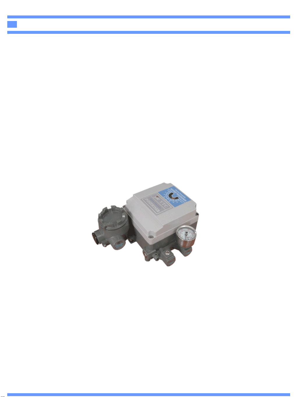
Electro-Pneumatic Positioner YT-1000R
13. CAUTION AND HANDLING
cDo not apply large vibration or impact to the positioner. It causes trouble.
The positioner must be handled very carefully during transportation and operation.
dIf the positioner is used under temperature outside of the specification, the sealing
materials deteriorate quickly and also the positioner may not operate normally.
eDo not remove the terminal cover at a dangerous position during power conduction.
fBe sure that the terminal cover and body cover are put on during the operation.
gIf you leave the positioner at the operation site for a long time without using it, put the
cover on it so that the rain water does not enter the positioner.
If the atmosphere is of high temperature or high humidity, take measures to avoid
condensation inside. The condensation control measures must be taken thoroughly for
export shipment.
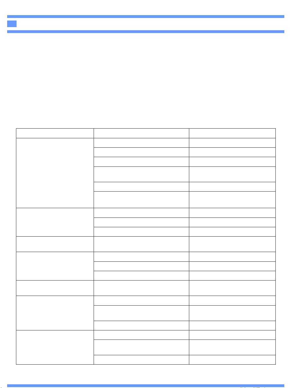
14. TROUBLE SHOOTING
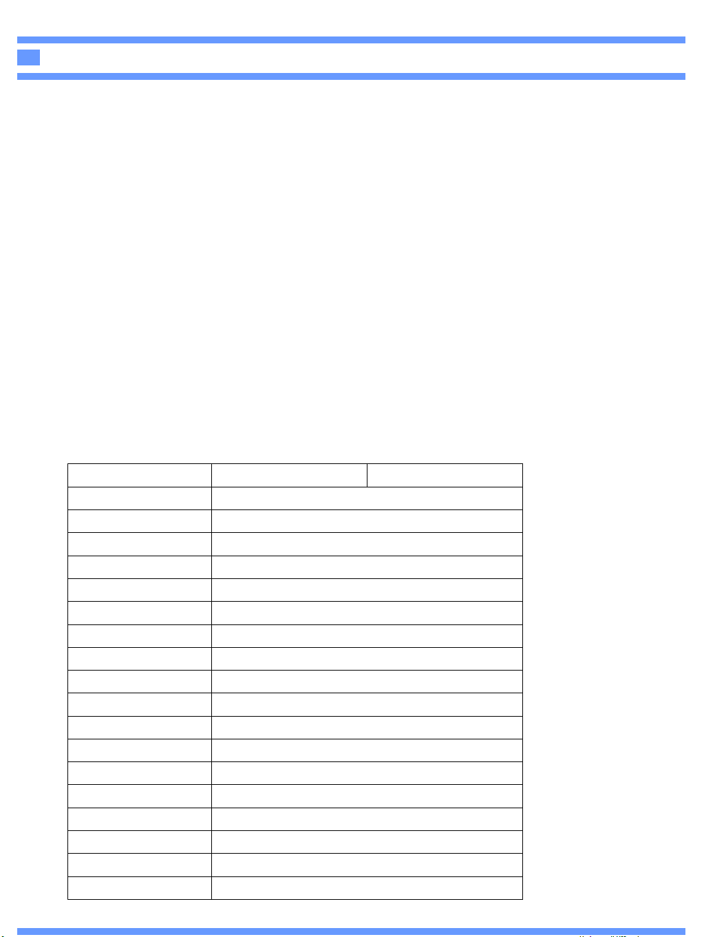
Replace Cam Shaft Cam shaft is worn out
Tighten connection
Loose connection of actuator and
poisitioner
Readjust Seat adjusterWrong setting of Seat Adjuster
Hysteresis is not good
Replace regulatorSupply pressure is unstable
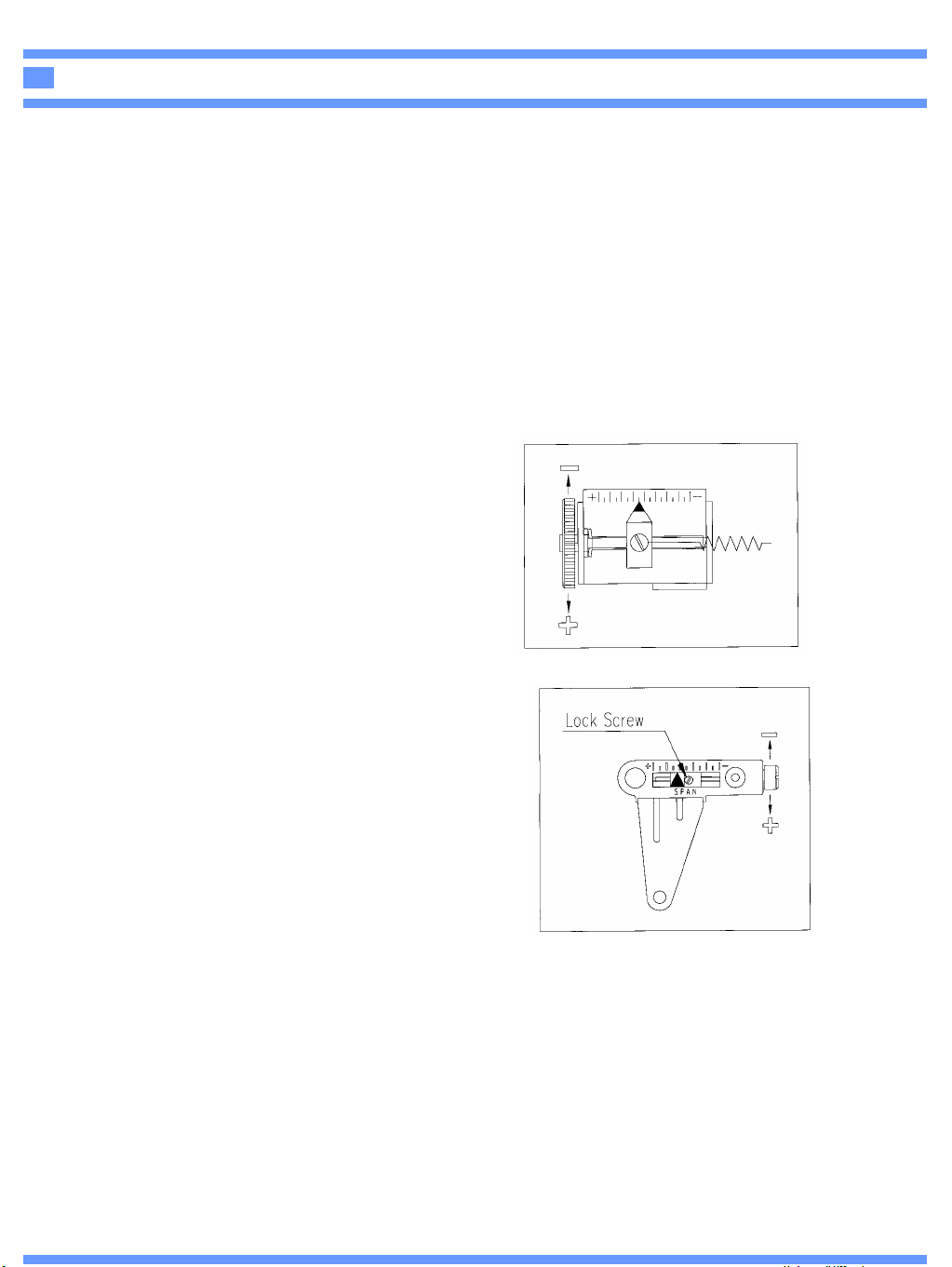
Readjustment of Zero, Span
Adjustment
Wrong Zero, Span adjustment
Readjust setting of feedback leverWrong setting of feedback lever
Linearity is not good
Correct position of tube
Wrong connection of OUT1 and
OUT2 tube
Actuator is operated by
On/Off only
Clean or replace fixed orificeClogged fixed orifice
Insert orificeToo low of actuator volume
Insert stabilizer springOff-positioned stabilizer spring
Hunting is occured
Clean nozzle or repalce Motor
Unit
Clogged nozzle
Output pressure is operated
by A/M Switch only
Clean or replace fixed orifice Clogged fixed orifice
Replace Motor UnitWrong contact or search of Flapper
Tighten or replace A/M switchLeakage of A/M switch
OUT1 pressure raised
And stay, does not
Come down
Correct setting and tighten
Loose or wrong setting of Feedback
Lever
Replace Motor UnitClogged Nozzle
Replace Motor Unit
Short or open circuit of terminal
Motor
Connect wiring (+) and (-)Wrong wiring for (+) and (-)
Tighten set screw of TerminalLoose connection
Input supply airToo low or none supply air
Not operated with Input
Signal applied
What to doCauseCondition