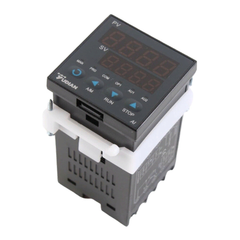
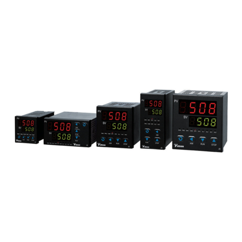
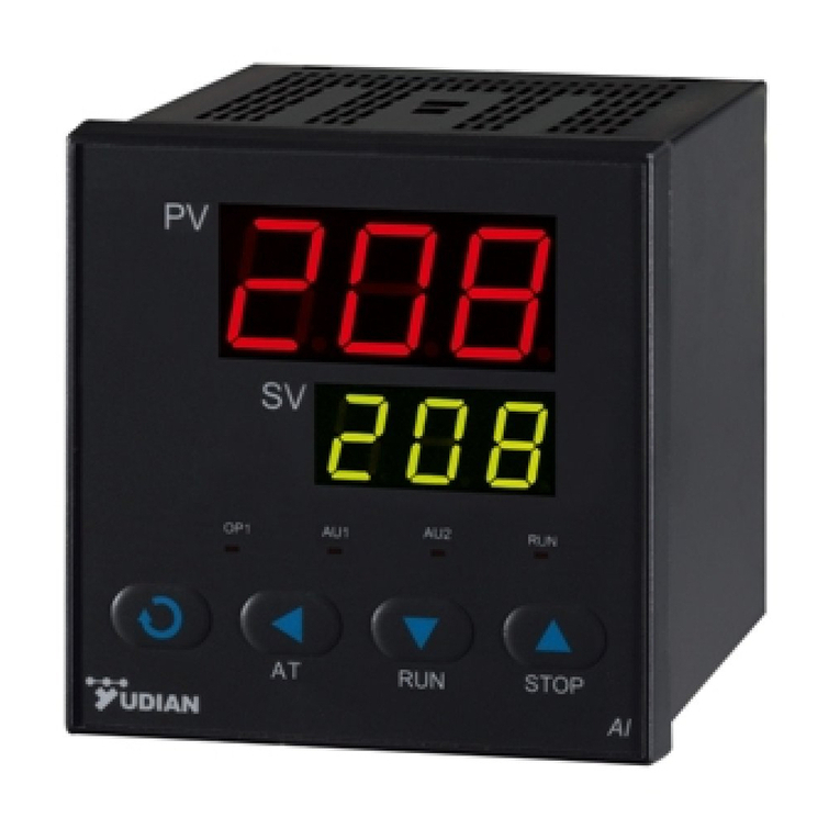
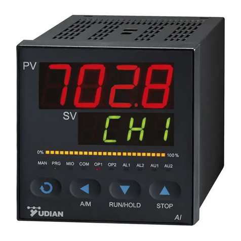
Yudian AI-710JM User manual

AI-3502M/3504M/3506M
人工智能温度控制器/工业调节器
产品说明书
Panel Mounting:
Remove the square anchor from the instrument.
Insert the instrument from panel front.
To fasten the instrument, put the anchor back
before wiring. The screws may be used for
further tightening.
48
48
95
10
45
45
75 75
INSTALLATION AND
OPERATION MANUAL
AI-710JM
Artificial Intelligent Temperautre Controller / Industrial Regulator
Software Version 8.2
Revise Date: May 2020
1. INSTALLATION
Dimensions and cut-out; panel mounting 2. TECHNICAL SPECIFICATIONS
Dimensions and cut-out; panel mounting
eEC
Display 2*4 digit LED, Red and Green
Keys 4 mechanical keys
Accuracy 0.1% full scale (FS)±1 digit
Input
(adustable digital
lter)
Pt100
Sampling time 80ms
Measurement
Range
-100...+300°C
Cold Junction
Error
0.05°C for each 1°C variation
Safety Detection of opening of probe
Temperature Shi ≤35ppm/°C
Regulating
Method
On/O (adjustable hytersis)
Articial Intelligent Regulating
with auto-tuning
Main Output SSR Voltage output 12VDC/30mA
(used to drive solid-state relay)
Action Main output (OUTP) with direct
(heating).
Conguration
alarm
4 type of alarm, high limit, low lim-
it, deviation high limit and devia-
tion low limit compared to setpoint.
Maximum 2 loops. Temporarily
disable during rst power on.
Power Supply 100~240VAC, -15%, +10% /
50~60Hz; 120~240VDC; or
24VDC/AC, -15%, +10%.
Power
Consumption
≤0.5W (no output or alarm);
≤4W (Maximum)
Opearating and
Storage
Environment
Temperature -10~60°C
Humidity ≤90%RH

4. CONNECTIONS
e connections may be varied due to
rmware upgrade or tailor-made order.
Please follow the connection diagram
attached to the instrument.
Signal input
Input from TC is connected to 9 (posi-
tive) and 10 (negative).
Control Output
Solid-state relay (SSR) output of 12VD-
C/30mA is connected to 7 (positive)
and 6 (negative).
Alarms
Alarm 1 (coded as AU1) is connected to
3 (NO) and 5 (common).
Alarm 2 (coded as AU2) is connected to
4 (NO) and 5 (common).
3. DESCRIPTION OF FACEPLATE
1 Upper display window:
Displays PV, parameter code, etc.
2 Lower display window:
Displays SV, parameter value, or alarm message
3 Setup key:
For accessing parameter table and conforming param-
eter modication.
4 Cursor shiing (or control operation)
5 Value down key
(or switch between RUN/HOLD)
6 Value uo key (or STOP)
ese value down and up keys raise or lower the value
of the displayed function. e raising (lowering) speed is
proportional to the time the key is pushed. e procedure
is not cyclical. When the maximum (minimum) of the
setting range is reached with the key pushed, the raise
(lower) function stops.
7 Six LED indicating lights:
MAN – Not used
PRG – Control is in action
COM - Communiction with host device in action
OP1 - Main output in action
AU1 - Alarm at AU1 on
AU2 - Alarm at AU2 on
AI-3502M/3504M/3506M
人工智能温度控制器/工业调节器
产品说明书

6. OPERATION
Parameter Setting
At the basic display, press and hold for about 2
seconds to access Field Parameter Table. Press
to proceed to next parameter. Press , or to
modify values. Press to decrease the value.
Press to increase the value. ere is a dot ashing
while the value is changing just like a cursor. Hold
the keys will speed up the value changing speed, as
well as the ashing frequency of the cursor.
Press to move the designated digit position.
Press to save and proceed to the next parameter.
Hold to scroll down the parameter table quickly.
Press and hold more than 2 seconds goes back
to the previous parameter. Press and hold (don’t
release) plus simultaneously escape parameter
setting back to Basic Display. e instrument will
automatically escape to Basic Display if no key is
pressed for 25 seconds but any change made to the
last parameter will not be saved.
Short-cut Keys
Certain frequently used operations can be done by
short-cut keys. ose keys can be disabled.
Changing SV: Press , or to change.
Auto-tuning (AT): Press and hold for about 2 sec-
onds until “At” shows up. Press to toggle “oFF” to
“on” in the lower display. Press to start auto-tun-
ing. e lower display will ash “At”. Aer two
oscillating cycles in “ON-OFF” control mode, PID
parameters will be calculated. To quit auto-turn-
ing, perform the same operation by pressing for
2 seconds. Change “on” to “oFF” and press to
conrm to quit.
Note
1. Advanced articial intelligent technology and PID regulating algo-
rithm by AI-710JM, which is named as “APID” is able to overcome the
overshoot issue by standard PID algorithm.
2. PID values vary from dierent system. Before activating the
auto-tuning, set point value, SV, should be set at the commonly
used value or mean value. Set the SV to a maximum one if the heat
isolation of a furnace is good. SV value is not allowed to be changed
during auto-tuning. e time required for this process may takes
seconds to hours.
3. Control Hysteresis, CHYS, aects the result of auto-tuning too.
Generally the least the CHYS, the higher is the PID auto-tuning accu-
racy. However low CHYS value may cause incorrect ON-OFF output
during uctuating input. CHYS=2.0 is recommended.
4. e PID values may not give the best performance immediately
aer the auto-tuning is nished. e performance will gradually
improve over some time because there is a learning feature.
5. Regardless of auto-tuning or manual tuning, the control period, Ctl,
will be limited not longer than 3 seconds, no matter what value it is
set previously, to increase the accuracy and to provide better response
time (manual tuning).
5. DISPLAY
Basic Display
When the instrument is powered, the upper display
and lower display show the model number and rm-
ware version respectively. Aer around 3 seconds,
the displays show the process value (PV) and set
value (SV) respectively. is basic display remains
until there is a key pressed.
System Message
Following warning or status message may show up.
Symbol Description
orAL Out-of-range alarm due to incorrent
input specication / Input wires
disconnected / Broken thermocouple
/ Short-circuited input #
HIAL High limit alarm*
LoAL Low limit alarm*
HdAL Deviation high alarm*
LdAL Deviation low alarm*
EErr Internal data lost. Factory repair
required.
StoP e instrument is in STOP status. No
output is given out.
* The alarm messages can be turned o by setting parameter AdIS to
oFF.
# When orAL appeared, the instrument will cut o the output after
a while.

8. PARAMETER SETTING
Customization of Field Parameters
Field Parameter Table is a subset of the Complete
Parameter Table. Maximum 8 Field Parameters can
be extracted to access directly without entering the
password (PASd) in parameter lock (loc) to speed
up operation workow in the eld.
If not all 8 eld parameters are used, the rst idle
parameter is recommended to be “nonE”.
Field Parameters Default Setting *
EP1 HiAL
EP2 LoAL
EP3 HdAL
EP4 LdAL
EP5 nonE
EP6 nonE
EP7 nonE
EP8 nonE
Loc 0
Example: If fast access to high limit alarm, high
deviation alarm and auto-tuning is needed, set
EP1=HIAL, EP2=HdAL, EP3=At,
EP4...EP8=nonE.
* e default settings may vary due to minor rmware version update
or order request.
Master password is stored in PASd. By default,
PASd =808. ere is no password reset feature. If
the password is lost, only rmware reload in factory
can reset the password.
loc denes dierent access levels of Field Param-
eters.
Loc SV At,
Auto
-tuning
Field
Param-
ter
Table
Complete
Parame-
ter Table
Short-cut
(Program
run/
HoLd/
SToP)
0√ √ √ X √
1√ X √ X X
2X X √ X √
3X X √ X X
4...255 X X X X X
PASd √ √ √ √ √
√: Allowed to modify or execute
X: Prohibited to modify or execute
7. FLOWCHART

8. PARAMETER SETTING (Continued)
Complete Parameters Table
e parameters is listed under 8 groups which is alarm, control, input, output, communication, system, set
point and Field Parameters.
Parameter Parameter Ttile Description Range of
Setting
HiAL High Limit Alarm Alarm turns on when PV>HIAL
Alarm turns o when PV<HIAL-AHYS,
Set to the maximum value to disable the alarm.
Alarm output location can be dened by parameter AOP. All alarms can be
assigned to AL1, AL2, AU1, AU2 or none. More alarm allocation is explained
in AOP section below.
-9990~
+32000 units
LoAL Low Limit Alarm Alarm turns on when PV<LoAL
Alarm turns o when PV>LoAL+AHYS
Set to the minimum value to disable the alarm.
HIAL and LoAL can be assigned as deviation alarms. Details please refer to
the description of parameter AF.
HdAL Deviation High
Alarm
Alarm turns on when PV-SV>HdAL;
Alarm turns o when PV-SV<HdAL-AHYS
Set to the maximum value to disable the alarm.
LdAL Deviation Low
Alarm
Alarm turns on when PV-SV<LdAL
Alarm turns o when PV-SV>LdAL+AHYS
Set to the minimum value to disable the alarm.
HdAL and LdAL can be assigned as absolute high limit and low limit alarms.
Details please refer to the description of parameter AF.
AHyS Alarm Hysteresis Also known as dead band or lag. To avoid frequent alarm on-o action caused
by the uctuation of PV. Usage of AHYS is shown above.
0~2000 units
AdiS Alarm Display oFF: Hide alarm messages in the lower display
on: Alternately display alarm message in the lower display [Recommended]
oFF / on
AOP Alarm Output
Position
Assign alarm (HdAL/LdAL/LoAL/HiAL) to dierent module slot position
(AL1/AL2/AU1/AU2)
AOP Code HdAL LdAL LoAL HiAL
0: Disabled
1: AL1 (ALM slot) N/A N/A N/A N/A
2: AL2 (ALM slot) N/A N/A N/A N/A
3: AU1 (AUX slot)
4: AU2 (AUX slot)*
Example: AOP=3303
HdAL and LdAL are sent to AU1. LoAL is disabled. HiAL is sent to AU1.
L3 dual relay output module must be install in AUX slot to use AU2.
0~6666
CtrL Control Mode onoF: on-o control, for situation not requiring high precision
APid: advanced articial intelligence PID control. (Recommended)
nPId: standard PID algorithm with anti integral-saturation function (no in-
tegral when PV-SV > proportional band)
onoF/
APid/
nPid
Srun Running Status run: Control is in eect. “PRG” indicator lights up.
StoP: Control is stopped. Lower display keeps ashing StoP. “PRG” indi-
cator goes o.
HoLd: Control is paused.
StoP /
run /
HoLd
ALARM

Parameter Parameter Ttile Description Range of
Setting
Act Acting Method rE: Reverse acting. Increase in measured variable causes a decrease in the
output, such as heating control.
dr: Direct acting. Increase in measured variable causes an increase in the
output, such as refrigerating control.
rEbA: Reverse acting with low limit alarm and deviation low alarm blocking
at the beginning of power on.
drbA: Direct acting with high limit alarm and deviation high alarm blocking
at the beginning of power on.
rE
dr
rEbA
drbA
At Auto-Tuning oFF: Autotuning function (At) is disabled.
on: Activate auto-turning (automatically adjust P, i, dand Ctiparameter). It
will switch to oFF when auto-tuning is completed.
FoFF : Auto-tuning function is disabled and prohibited to activate by short-
cut key directly from panel .
oFF
On
FoFF
PProportional Band Proportional band in PID and APID control. Instead of taking the percentage
of the measurement range, the unit is the same as PV.
Generally, optimal P, i, dand Ctiare calcuated by auto-tuning. ese pa-
rameters can be manually entered if the system is known before such as the
manufacturing process of heating machines.
1~32000 units
iTime of Integral Denes the integral time, in unit of second. i=0 disables the eect of inte-
gration.
0~9999
seconds
dTime of Derivative Denes the derivative time, in unit of 0.1 second. d=0 disables the eect of
derivation.
0~999.9
seconds
Cti Control Period For solid-state relay (SSR) output, it is generally set to 5 ~ 3.0 sec. 0.2~300.0 Sec
CHys Control Hysteresis CHYS is used for on-o control to avoid frequent on-o action of relay.
For a reverse acting (heating) system, when PV > SV, output turns o; when
PV<SV-CHYS, output turns on.
For a direct acting (cooling) system, when PV<SV, output turns o; when
PV>SV+CHYS, output turns on.
0~2000
inP Input
Specication Code
Select input specication. Inut is xed in this instrument with corresponding
range of measurement
22 : Pt100(-100~+300.00°C)
22
dpt Display
Resolution
Four display formats (0, 0.0, 0.00, 0.000) are selectable.
When inP=22, the internal resolution is 0.01°C. Display format 0.0 or 0.00
are available.
0.0
0.00
SCL Source Low Limit Dene scale low limit of input. . -9990~
+32000 units
SCH Souce High Limit Dene scale high limit of input.
Scb Source Bias Scb is used to shi input to compensate the error caused by transducer, input
signal.
PV aer compensation=PV before compensation + Scb
It is generally set to 0. e incorrect setting will cause measurement inac-
curacy.
-1999~ +4000
units
Filt Input Filter e value of FILt will determine the ability of ltering noise.
When a large value is set, the measurement input is stabilized but the re-
sponse speed is slow. If high interference exists, you can increase parameter
“FILt” gradually to make momentary uctuation of measured value less than
2 to 5 digits. When the instrument is being metrological veried, FILt can
be set as 0 or 1 to shorten the response time. e unit of FILt is 0.5 second.
0~40
OPt Main Output Type SSr: Output SSR drive voltage. Module G should be installed. e output
power can be adjusted by the on-o time proportion. e period (CtI) is gen-
erally 0.5~3.0 seconds.
SSr
OPH Output Upper
Limit
OPH limits the maximum of OUTP (main output) when PV<OEF. e sys-
tem automatically adjust OPH to 100% when PV>OEF.
0~110%
OEF Eective Range
of OPH
When PV<OEF, the upper limit of OUTP is OPH; when PV>OEF, the upper
limit of OUTP is 100%.
Example: is applies to the scenario of low temperature and heating is not in
full power, such as drying the furnace internal chamber or low rate of heating,
Certain heating elements are allowed to use up to 30% heating power below
150°C, set OEF=150.0, OPH=30 (%)
-999~ +3200
INPUT
OUTPUT CONTROL

Parameter Parameter Ttile Description Range of
Setting
Addr Communication
address
In the same communication line, dierent instrument should be set to dif-
ferent address.
0~80
bAud Baud rate Dene baud rate within 1200~19,200bit/s 0~19.2K
AF Advanced
function
AF is used to select advanced function. e value of AF is calculated as below:
AF=A x 1 + B x 2 + C x 4 + D x 8 + E x 16 + F x 32 + G x 64 + H x 128
A=0*: HdAL and LdAL work as deviation high and low limit alarms;
A=1: HdAL and LdAL work as high and low limit alarms, and the instrument
can have two groups of high and low limit alarms.
B=0: Alarm and control hysteresis work as unilateral hysteresis;
B=1: As bilateral hysteresis.
C=0: e light bar indicates the output value;
C=1: e light bar indicates the process value (for instruments with light bar
only);
D=0: e common password “808” can access full parameter table;
D=1: e password to access parameter table will be “PASd” value;
E=0: Normal application on HIAL and LoAL;
E=1: HIAL and LoAL changed to deviation high alarm and deviation low
alarm;
F=0: Fine control mode. e internal control resolution is 10 times as much
as that of display, but the maximum display value during linear input is 3,200
units;
F=1: Wide range display mode which is selected when the required display
value is larger than 3,200;
G=0: When the sensor is broken, PV value will increase and trigger the high
limit alarm. (High limit alarm should be set below the input scale high limit.)
G=1, When the sensor is broken, PV value will increase and NOT trigger the
high limit alarm. Pleaes note that High Limit Alarm will delay for 30 seconds
when this feature is activated.
H=0, AIBUS communication
H=1, MODBUS compatible communication.
*AF=0 is recommended.
0~255
PASd Password When PASd=0~255 OR AF.D=0, setting Loc=808 will enter this complete
parameter table.
When PASd=256~9999 AND AF.D=1, only Loc=PASd can access this com-
plete parameter table.
Pay attention to congure PASd. If the password is lost, there is no way to
access the parameter table again until it is sent to factory reset.
0~9999
SPL Low Limit of SV Minimum value that SV is allowed to be. -999~+3000
unit
SPH Upper limit of SV Maximum value that SV is allowed to be.
EP1
Customized Field
Parameter
Field Parameters 1~8 can be congured for commonly used parameters with-
out entering lock password. Set nonE to hide the particular EP parameter.
H1AL(Default)
EP2 LoAL(Default)
EP3 HdAL(Default)
EP4 LdAL(Default)
EP5 nonE(Default)
EP6 nonE(Default)
EP7 nonE(Default)
EP8 nonE(Default)
SYSTEM
FIELD PARAMETER
COMMUNICATION
SET POINT

9. Advance Function
Alarm blocking at the beginning of power on
Sometimes the fault alarm may occur at the
beginning of power on. In a heating system, at the
beginning of power on, its temperature is much low-
er than the set point. If low limit and deviation low
limit are set and the alarm conditions are satised,
the instrument should alarm, but there is no prob-
lem in the system. Contrarily, in an refrigerating
system, the unnecessary high limit or deviation high
limit alarm may occur at the beginning of power
on. erefore, AI instruments oer the function of
alarm blocking at the beginning of power on. When
Act is set to rEbA or drbA, the corresponding low
or high alarms are blocked until the alarm condition
rst clears. If the alarm condition is satised again,
the alarm will work.
Communication function
S or S4 module can be installed at COMM slot to
communicate with a computer. e instrument can
be controlled by computer. AI instruments can be
connected to the computer through RS232 or USB
communication port. Every communication port of
a computer can connect up to 60 AI instruments,
or 80 AI instruments if a repeater is installed. A
computer with 2 communication ports can connect
up to 160 instruments. Please note that every instru-
ment connecting to the same communication line
should be set to a unique communication address.
If the number of instrument are enough, 2 or more
computers can be used and a local network can be
set up.
If users want to develop their own distributed
control system by themselves, the communication
protocol of AI instruments can be freely oered.
ere are many distributed control system soware
support AI instruments.
Fine control
Fine control means that the PID operating reso-
lution is ten times as high as the display resolu-
tion. For example, the temperature signal of the
instrument displays 1°C, but the internal PID still
operate and control as per 0.1°C resolution, thus can
realize the control accuracy much higher than the
display resolution. In former AI series instruments,
only temperature signal adopts ne control mode.
e new edition approves default ne control mode
when the displayed value range is below 3,000 char-
acters (on most of industrial application occasions,
the value should not exceed 3,000 characters) during
linear input, so as to get higher control accuracy and
more stable output. When the required display value
range is larger than 3,000, AF.F=1.
User-defined input specifications
When INP is set to 64 larger than preset value, the
input specication of the instrument switches to
user-dened input. Set INP=22+64=86. e linear
table can be edited, the setup method is as follows:
set Loc parameter as 3698, and then enter the table
setup status (if the original Loc=808, the Loc shall
be zeroed, exit the parameter setting status, and then
reenter the parameter setting status and set Loc as
3698). Of which the parameter A 00 denes the use
of the table, 0 is used to input non-linear measuring,
1 is used to high temperature furnace non-linear
control, with parameters of A01~A04 and d00~d60
respectively set as follows:
A 00=0 (xed)
A 01 denes input speccation
Formula: A 01=A*1+E*16+G×*64
A is the range of measurement:
A=0: 0~20mV (0-80Ω);
A=1: 0~60mV (0-240Ω);
A=2: 0~100mV (0-400Ω);
A=3: 0~1V;
A=4: 0~5V,
A=10, 0~20mA or 0~10V (MIO position installed with I4 or I31
module)
E=0: Output value still should be determined as per ScH/ScL parame-
ters during linear input of signals.
E=1: e table output value is the displayed value.
G is the type of sensor.
G=0: thermocouple;
G=1: thermal resistance;
G=2: linear voltage (current);
G=3: linear resistance
For instance: Pt100 input; range 30~40oC; every adjustment section
at one degree
Long press Setup. Set inP=86. Set dPt=0.0.
LOC=3698 (Enter user-dened multi-section adjustment)
A00 = 0
A01 = 82 (Function setup. Set Pt100 conguration 82)
A02 = 300.0 (Initial temperature at 30oC)
A03 = 100.0
A04 = 10.0
d00 = 30.00 d01 = 31.00 d02 = 32.00
d03 = 33.00 d04 = 34.00 d05 = 35.00
d06 = 36.00 d07 = 37.00 d08 = 38.00
d09 = 39.00 d10 = 40.00
Set the deivation directly to the particular temperature. If it is show-
ing 37oC but it is found higher, set d07 a little bit lower than 37.00.
YUDIAN Automation Co., Limited
YUDIAN (H.K) Automation Co., Limited
12/F, Chun Hoi Commercial Building, 688 Shanghai Street,
Kowloon, Hong Kong
http://www.yudian.com.hk
Table of contents
Other Yudian Temperature Controllers manuals
Popular Temperature Controllers manuals by other brands

dixell
dixell IC200CX Series Quick reference guide

Johnson Controls
Johnson Controls MS4PMUHVT quick start guide

Hoval
Hoval TopVent TP operating instructions

Stafford Instruments
Stafford Instruments ST312 User handbook

Heatcraft Refrigeration Products
Heatcraft Refrigeration Products Masterlog 4 User handbook

Sub-Zero
Sub-Zero SZ-7510-P-DI operating instructions