YUSHI LM330 User manual

Leeb Hardness Tester
LM330
Operating Manual
YUSHI INSTRUMENTS
CONTENTS
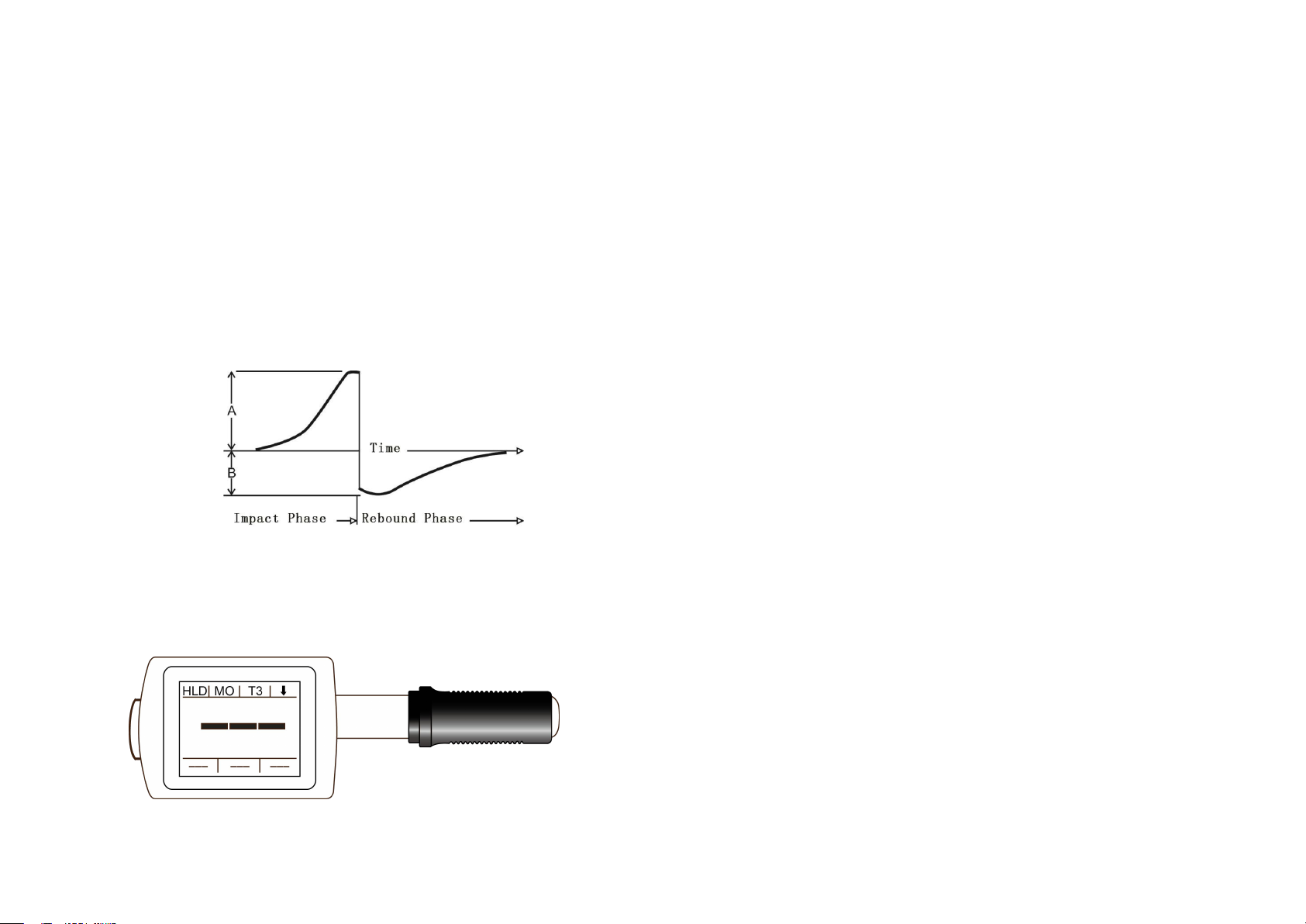
1. Principle of Leeb Hardness Testing Method.............................. 1
2. Instrument and Impact Device Diagram ...............................................1
2.1 Instrument Diagram......................................................................... 1
2.2 Standard Configuration .................................................................. 2
2.3 Optional Accessories........................................................................2
3. Functions And Applications.......................................................................... 2
3.1 Technical Specifications...................................................................2
3.2 Applications......................................................................................3
4.Pre-treatment of Workpiece............................................................................ 4
4.1 Workpiece Requirements.............................................................................4
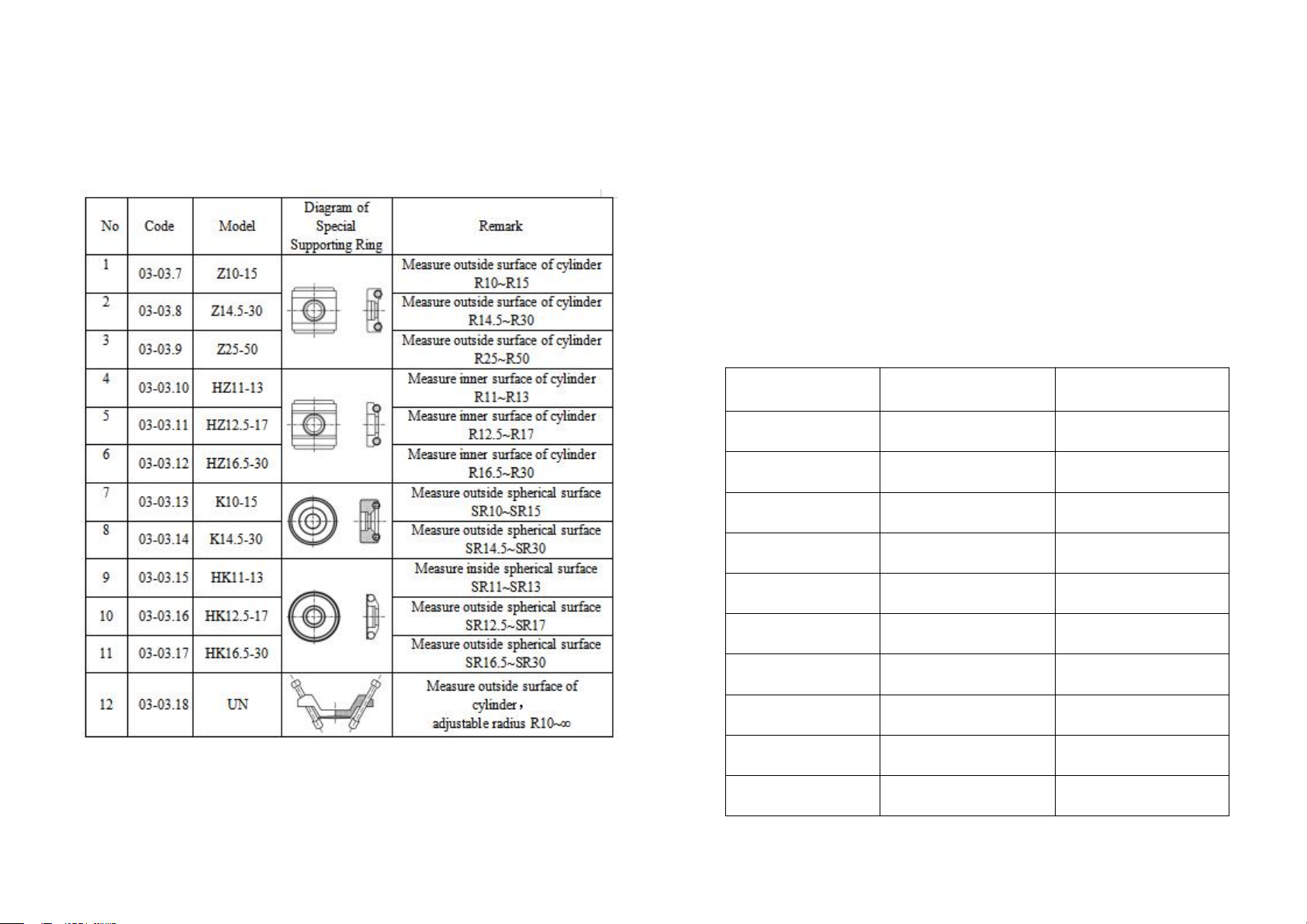
4.2 Selection of Supporting Ring.......................................................................5
5. Operation.................................................................................................................6
5.1 Turn On the Instrument.............................................................................6
5.2 Parameters Setting..........................................................................6
5.2.1 Material.............................................................................. 6
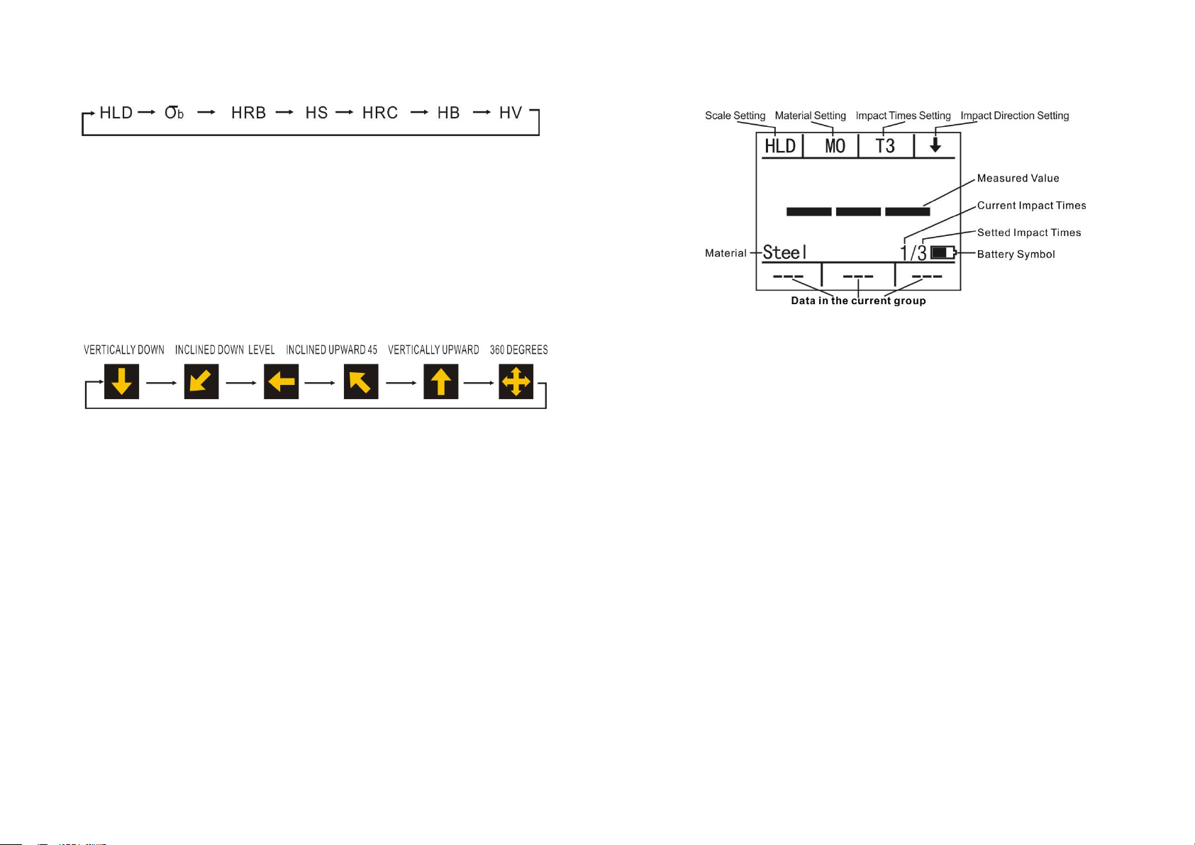
5.2.2 Hardness Scale................................................................... 7
5.2.3 Impact Times......................................................................7
5.2.4 Impact Direction................................................................ 7
5.3 Measuring......................................................................................7
5.3.1 Operating............................................................................7
5.4 Interface Description.....................................................................8
5.4.1 Default Interface ............................................................ 9
5.4.2 Calibration Interface.......................................................... 9
5.4.3 Sub-interface of Read The Storage ................................10
5.4.4 Sub-interface of Read The Storage..................................10
5.4.5 Setting and Shutdown Interface....................................... 11
5.4.6 Storage Data Transmission...............................................11
6.Maintenance&Servicing.................................................................................11

1. Principle of Leeb Hardness Testing Method
The impact body, which is equipped with tungsten carbide, impacts
into the work piece and rebounds back. The rebound and impact
velocities are measured at the 1mm point from the work piece in the
following way: the integrated permanent magnet will produce directly
proportional voltage with the impact velocity. The Leeb hardness
values are calculated by the following formula:
HL=1000×( Vb/ Va)
In Which:HL: Leeb hardness values
Vb: the voltage produced during the rebound of impact body
Va: the voltage produced during the impact of impact body
Figure 1 shows the voltage produced during the impact and rebound
of impact body:voltage features of output signal
Figure 1.1
2. Instrument and Impact Device Diagram
2.1 Instrument Diagram
Figure 2.1
2.2 Standard Configuration
Main Unit (With D type impact device)
HLD Value Standard Test Block
DataView Software
USB Communication Cable
Small Supporting Ring
Cleaning Brush
Operating Manual
Instrument Case
One AAA Battery
2.3 Optional Accessories
Impact Device: DL Connector
Standard Test Block
Standard Supporting Ring
Special Supporting Rings
Small Supporting Ring
3. Functions and Applications
3.1 Technical Specifications
Measuring Method: Leeb hardness testing method
Hardness Scale: HL, HB, HRB, HRC, HV, HS Strength (σb).
MeasuringRange: HLD(200-960), HRC(19.8-68.5), HB(30-651),
HV(80-976), HS (26.4-99.5), HRB (13.5-100), σb (375-2639).
Impact Device: D type impact device (Standard); Interchangeable DL
type impact device
1 2

Accuracy: ±6HLD (HLD=800), Repeatability 6HLD (HLD=800)
Measuring Direction: Vertically downward, inclined downward, Level,
inclined upward, vertically upward, 360 degrees by manual setting.
Material: Steel & Cast Steel, Stainless Steel, GC IRON, NC IRON,
Cast Aluminum Alloy, Copper-Zinc Alloy, Copper-Tin Alloy, Brass,
Forging Steel, Alloy Tool Steel
Resolution: 1HL, 1HV, 1HB, 0.1HRB, 0.1HRC, 0.1HS
Display: 1.77 inch color TFT LCD screen
Memory: 1000 groups ( each group include 2-6 testing values and 1
average value)
Communication Port: USB 2.0
Power: 1 AAA Battery,1.5V
Working Temperature: -10℃~ +50℃
Size: 149mm*45mm
Weight: 110g ( include battery )
Battery: 10g
Standard: GB/T 17394-1998, ASTM A956
3.2 Applications
Installed machinery and permanent assembly parts
Mould cavity
Heavy workpieces
Failure analysis of pressure vessel, turbine and other equipments
Small test area
The production line of bearings and other parts
Distinguish the material of the metal material warehouse
4 Pre-Treatment of Workpiece
4.1 Workpiece Requirements
1. Surface roughness is an important requirement for the test piece, it
should be smooth and no oil, or will cause measurement errors.The
surface roughness of workpiece should be less than 2μm.
2. Sample weight >5kg ,It can be tested directly without supporting.
Sample weight is 2~5kg, with overhanging part or thin wall workpiece,
it should be fixed and supported with object more than 5kg weight to
avoid deformation or moving.
Sample weight <2kg, it should be tight coupled with the supporting
object of the the weight more than 5 kg, and the surface of supporting
body should be flat, smooth, and no excess couplant, the testing
direction must be perpendicular to the coupling surface.
3. Other requirements of the sample: Sample weight ≥ 0.1kg,
Sample thickness ≥
5mm,Hardened-layer depth >0.8mm.
4. While the supporting body being clamped ,the impact direction
should be perpendicular to the testing surface.
5. When sample is large area of plate, long rod, or curved workepiece,
even fairly heavy and thick, it may still cause deformation and
instability of the workpiece and cause incorrect test value. So the back
of the test position should be reinforced and supported.
6. The magnetism of the sample should be less than 30 gauss.
3 4

4.2 Selection of Supporting Ring
When the curvature radius (R) of testing sample surface is smaller
than 30mm and greater than 11mm, the small supporting ring should
be used, or select our special supporting ring(Optional) to obtain the
best test condition.
Table 4.1
5. Operation
5.1 Turn on the Instrument
Press power on button (D) to turn on the instrument, the screen
display the default interface, then power on again to display the last
parameters automatically.
5.2 Parameters Setting
5.2.1 Material Setting
Press material setting button (B) to select the material, material Code
No. from M0~M9:
Material Code No.
Hardness
Tensile Strength
0
Steel and Cast Steel
Carbon Steel
1
Gray Cast IRON
Cr-Ni Steel
2
Nodular Cast IRON
Cr-Mo Steel
3
Cast Aluminum Alloy
Cr-V Steel
4
Brass
Cr-Mn-Si Steel
5
Bronze
High-Strength Steel
6
Copper
Stainless Steel
7
Stainless Steel
Cr-Ni-Mo Steel
8
Forging Steel
Chrome Steel
9
Alloy Tool Steel
Table 5.1
5 6

5.2.2 Hardness Scale Setting
Press scale setting button (A) to select the hardness scale and strength;
Note: when choosing DL probe in the storage interface, “HLD” displays as “HLDL”.
Figure 5.2
5.2.3 Impact Times Setting
Press times button (C) to set the impact times from T1~T6, which will
calculate the AVE value after the certain impacts.
5.2.4 Impact Direction Setting
Press direction button (D) to select impact direction.
Figure5.3
5.3 Measuring
5.3.1 Operating
Start measuring after finish the parameters setting.
◆Load the impact body: Pushing the loading-tube until contact is felt.
Then allow it to slowly return to the starting position locking the impact
body.
◆Fixed position: Press the impact device support ring firmly on the
surface of the sample.
◆Release the impact body: Press the release button on the upside of
the impact device to test. The sample and the impact device as well as
the operator are all required to be stable now. And the direction of the
force should be through the axis of the impact device.
◆After testing, the screen displays as following, the tester will save
testing results automatically, or it won’t save testing results if the
testing value is invalid. After several testing, the recent testing values
will display in sequence at the bottom of the screen.
5.4 Interface Description
Figure 5.4
This instrument has total four main interfaces and one sub-interface
(under the storage interface), long press the four buttons to switch to
the corresponding four interface: default interface, calibration interface,
storage interface, setting interface.
The A button corresponding to the default interface (booting interface):
including scale (A), material (B), impact times (C), boot and impact
direction (D).
The B button corresponding to the calibration interface: including
calibration (A), increase (C) and decrease (D) calibration value. (To
operate when mean value appears).
The C button corresponding to the storage interface: including save(A)
(effective under the mean value), read (B), delete the current value(C),
(D) the saved hardness values can be read and deleted when
enter into the read interface.
Click B button to switch the sub-interface to read the stored values.
The D button corresponding to the setting interface: Language, impact
device, bright adjustment and power off can be settled under this
interface.
7 8

5.4.1 Default Interface
A→Hardness sacle switch button B→Material switch button
C→Impact times selection button, calculating the mean value
according to the selected times. D→Impact direction selection
button
Figure 5.5
5.4.2 Calibration Interface ( Factory Calibrated )
Measuring error can be usually caused by impact device abrasion
after long time using. So it is necessary to correct the error by
calibration procedure to make the measurement accurate.
A→Calibration button, can be operated only if the mean value effective.
C→Increase button, can be operated only if the mean value effective.
D→decrease button, can be operated only if the mean value effective.
Note: The function of switch D/DL impact device is in the setting
interface (5.9). The standard configuration D probe, calibration is
needed after replacing to DL impact device.
Figure 5.6
5.4.3 Storage Interface
A→Save button, can be operated once after the mean value effective.
B→Read the storage button, will switch to (5.8) read the storage
sub-interface .
C→Delete button, only the current value can be deleted.
6 testing results and 1 mean value each group can be stored.Press
read button (B) to enter the reading mode, which displayed in cyan
color (5.8)
Figure 5.7
5.4.4 Sub-interface of Read the Storage
A→Return to storage interface
B→Delete the currently displayed stored value
C→Browse the stored value upwardly
D→Browse the stored value downwardly
Main displays the mean value, and sub displays three stored values.
9 10
Figure 5.8

5.4.5 Setting and Shutdown Interface
A→Language switch button: Simplified Chinese, Traditional Chinese,
Japanese, English and Spanish.
B→Impact device switch button, only DL probe is optional.
C→Brightness control button, total three levels.
D→Power off button
Figure 5.9
5.4.6 Storage Data Transmission
The data in stored can be transferred from the instrument to a PC via
communication software, for saving, statistic and analyzing the
measurement. (See the help documentation in communication
software for details)
6. Maintenance & Servicing
After long time using, please use the cleaning brush to clean the
tube and impact body.
Unscrew the support ring , take out the impact body.
Spiral the nylon brush in counter-clock direction into the
bottom of the tube and pull it out, repeat many times.
Install the impact body and support ring.
Release the impact body after testing every times.
Conversion Table between HLD Value and HLDL Value
11
HLD
300
304
306
308
310
314
316
318
322
324
HLDL
560
562
564
566
568
570
572
574
576
578
HLD
356
360
361
364
367
370
372
374
377
380
HLDL
602
604
606
608
610
612
614
616
618
620
HLD
410
413
415
418
420
423
425
429
431
433
HLDL
644
646
648
650
652
654
656
658
660
662
HLD
464
466
468
472
474
476
479
481
484
487
HLDL
686
688
690
692
694
696
698
700
702
704
HLD
518
521
524
527
530
532
534
537
540
544
HLDL
728
730
732
734
736
738
740
742
744
746
HLD
578
581
584
587
590
592
596
599
602
605
HLDL
770
772
774
776
778
780
782
784
786
788
HLD
644
647
650
654
657
660
664
667
670
674
HLDL
812
814
816
818
820
822
824
826
828
830
HLD
716
720
724
728
730
734
738
742
746
749
HLDL
854
856
858
860
862
864
866
868
870
872
HLD
793
797
800
804
808
812
815
819
823
826
HLDL
896
898
900
902
904
906
908
910
912
914
HLD
871
874
878
882
886
889
893
HLDL
938
940
942
944
946
948
950

328
330
334
336
338
340
344
346
348
352
354
580
582
584
586
588
590
592
594
596
598
600
383
386
387
390
392
395
398
400
403
405
408
622
624
626
628
630
632
634
636
638
640
642
436
438
440
444
446
448
451
453
456
458
461
664
666
668
670
672
674
676
678
680
682
684
490
492
495
497
500
502
505
508
510
513
516
706
708
710
712
714
716
718
720
722
724
726
546
548
551
554
557
560
563
566
569
572
574
748
750
752
754
756
758
760
762
764
766
768
608
611
614
617
620
624
627
630
634
637
640
790
792
794
796
798
800
802
804
806
808
810
678
681
684
688
691
695
698
702
706
709
712
832
834
836
838
840
842
844
846
848
850
852
752
756
760
764
768
771
774
778
782
786
789
874
876
878
880
882
884
886
888
890
892
894
830
834
837
841
845
849
852
856
860
864
867
916
918
920
922
924
926
928
930
932
934
936
Table of contents
Other YUSHI Test Equipment manuals
Popular Test Equipment manuals by other brands

Audio Precision
Audio Precision System Two Mounting instructions

Agilent Technologies
Agilent Technologies U1610/20A quick start guide

Tempo Fitness
Tempo Fitness Tele-Mate Pro TM-700 instruction manual

Elcometer
Elcometer 108 user guide

Tektronix
Tektronix MDO4104 Technical reference

FiT
FiT 500128 instruction manual