YUSHI LM500 User manual

Color Screen
Leeb Hardness Tester
LM500
Operating Manual
YUSHI INSTRUMENTS

CONTENTS
1.Principle of Leeb Hardness Testing Method................................1
2. Instrument and Impact Device Diagram.............................................2
2.1 Instrument Diagram ...................................................................... 2
2.2 D Type Impact Device Diagram....................................................... 3
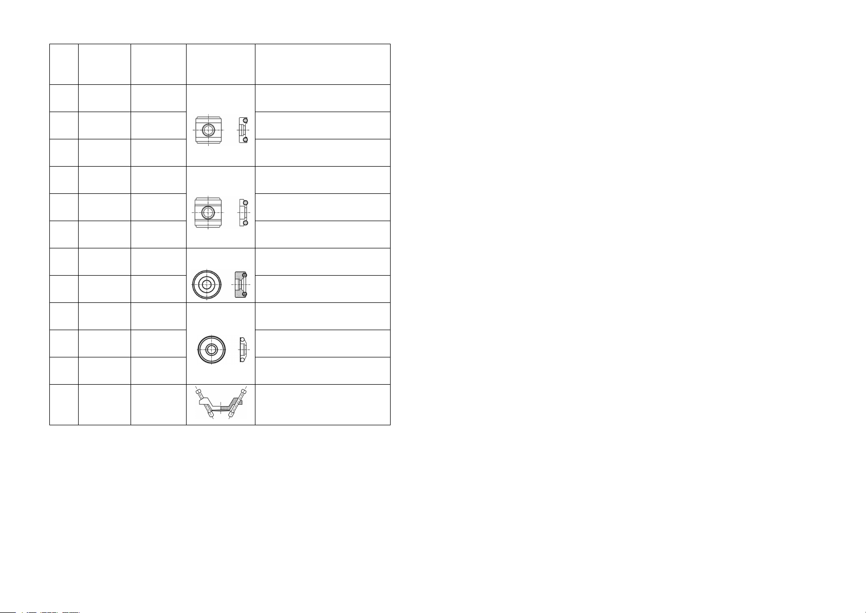
2.3 Types of Impact Device.................................................................... 4
2.4 Impact Devices Specification........................................................... 4
2.5 Standard Configuration.....................................................................6
2.6 Optional Accessories.........................................................................6
3.Functions and Applications..........................................................7
3.1 Technical Specifications................................................................... 7
3.2 Applications.......................................................................................8
4.Pre-Treatment of Workpiece........................................................ 8
4.1 Workpiece Requirements.................................................................. 8
4.1.1 Surface Roughness Requirements......................................... 8
4.1.2 Weight and Thickness Requirements.....................................9
4.1.3 Surface Hardened Layer Thickness....................................... 9
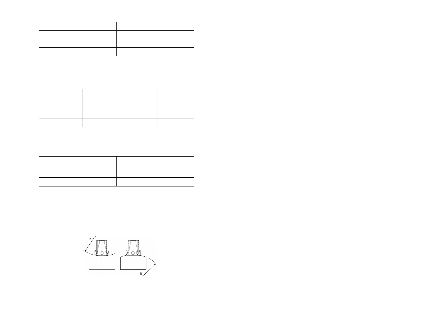
4.1.4 Curved Surface Requirement.................................................9
4.2 Support of Test Piece...................................................................... 10
5.Operation....................................................................................10
5.1 View Switching............................................................................... 10
5.2 Keyboard......................................................................................... 11
5.3 Turn on the Instrument....................................................................12
5.4 Parameters Setting...........................................................................12
5.4.1 File Number......................................................................... 12
5.4.2 Material................................................................................ 12
5.4.3 Hardness Scale..................................................................... 13
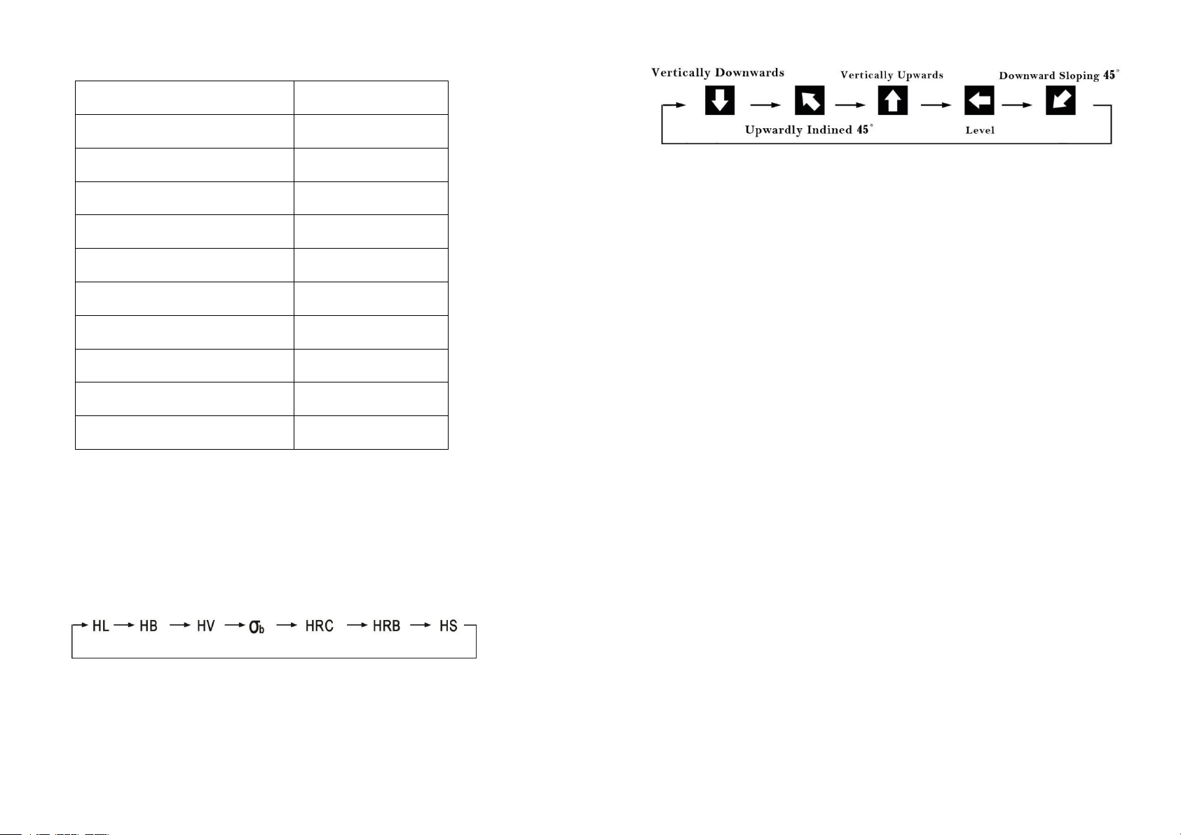
5.4.4 Impact Direction.................................................................. 13
5.4.5 Impact Times........................................................................14
5.4.6 Set Upper Limit and Lower Limit Alarm............................ 14
5.4.7 Set the types of the Impact Device...................................... 15
5.4.8 Languages............................................................................ 15
5.4.9 Auto Power-Off Setting ..................................................... 15
5.4.10 Delete All Files.................................................................. 15
5.5 Measuring........................................................................................15
5.6 Average Value..................................................................................16
5.7Delete the Gross Error Value Manually 16
5.8 Data Save and Read Setting............................................................16
5.8.1 Storage Testing Result....................................................... 16
5.8.2 Reading................................................................................ 17
5.8.3 Delete................................................................................... 17
5.8.4 Data Transmission........................................................................17
5.9 Calibration..................................................................................... 17
6. Maintenance & Servicing........................................................... ..18
6.1 Clean the Impact Device................................................................. 18

1.Principle of Leeb Hardness Testing Method
The impact body, which is equipped with tungsten carbide, impacts into the
work piece and rebounds back. The rebound and impact velocities are
measured at the 1mm point from the work piece in the following way: the
integrated permanent magnet will produce directly proportional voltage
with the impact velocity. The Leeb hardness values are calculated by the
following formula:
HL=1000×( Vb/ Va)
In Which:HL: Leeb hardness values
Vb: the voltage produced during the rebound of impact body
Va: the voltage produced during the impact of impact body
Figure 1 shows the voltage produced during the impact and rebound of
impact body:
voltage features of output signal
Figure 1.1
2. Instrument and Impact Device Diagram
2.1 Instrument Diagram
Figure 2.1
1 2

2.2 D Type Impact Device Diagram
Figure 2.2
2.3 Types of Impact Device
Figure 2.3
2.4 Impact Devices Specification:
Special Impact
Device
D/DC/DL
D+15
C
G
E
Impact Energy
11mJ
11mJ
11mJ
11mJ
11mJ
Mass of Impact Body
5.5g/7.2g
7.8g
3.0g
20.0g
5.5g
Test Tip Hardness
1600HV
1600HV
1600HV
1600HV
5000HV
Test Tip Diameter
3mm
3mm
3mm
5mm
3mm
Test Tip Material
Tungsten
Carbide
Tungsten
Carbide
Tungsten
Carbide
Tungsten
Carbide
Tungsten
Carbide
Impact.Device Diameter
20mm
20mm
20mm
30mm
20mm
Impact Device Length
86/147/75
162mm
141mm
254mm
155mm
Impact Device Weight
50g
80g
75g
250g
80g
Max.Hardness of
Sample
940HV
940HV
1000HV
650HV
1200HV
3 4

Average Surface
Roughness Ra:
1.6μm
1.6μm
0.4μm
6.3μm
1.6μm
Min.Weight.of
Sample:(kg)
Directly Measurable
Need Stable Support
Tightly Coupled
>5
2-5
0.05-2
>5
2-5
0.05-2
>1.5
0.5-1.5
0.02-0.5
>15
5-15
0.5-5
>5
2-5
0.05-2
Min.Thickness.of
Sample:
Tightly Coupled
Min.Depth.of
Hardnes Layers
5mm
》0.8mm
5mm
》0.8mm
1mm
》0.2mm
10mm
》1.2mm
5mm
》0.8mm
Indentation Dimension of Test Tip
With
300HV
Diameter
0.54mm
0.54mm
0.38mm
1.03mm
0.54mm
Depth
24μm
24μm
12μm
53μm
24μm
With
600HV
Diameter
0.54mm
0.54mm
0.32mm
0.90mm
0.54mm
Depth
17μm
17μm
8μm
41μm
17μm
With
800HV
Diameter
0.35mm
0.35mm
0.35mm
--
0.35mm
Depth
10μm
10μm
7μm
--
10μm
Impact Device Applicable Scope
DC
Used for very confined spaces such as holes, cylinders
internal measurement
DL
Used for extremely confined spaces.
D+15
Used for measuring in grooves, recessed surface.
C
Used for testing case hardened or thin walled components.
G
Used for solid heavy component, such as rough castings and
forgings.
E
Used for high hardness material.
Table 2.1
2.5 Standard Configuration
LM500 Main Unit
D type Impact Device
HLD Value Standard Test Block
DataView Software
USB Communication Cable
Small Supporting Ring
Cleaning Brush
2 AA Battery
Operation Manual
Instrument Case
2.6 Optional Accessories
Impact Device: C/G/DC/DL/D+15
Standard Test Block
Rubber Sheath
Belt
Standard Supporting Ring
Small Supporting Ring
Special Supporting Rings ( See table 2.2 )
5 6

No.
Code
Model
Special
Support Ring
Sketch
Remark
1
03-03.7
Z10-15
Measure outside the cylindrical
surface R10~R15
2
03-03.8
Z14.5-30
Measure outside the cylindrical
surface R14.5~R30
3
03-03.9
Z25-50
Measure outside the cylindrical
surface R25~R50
4
03-03.10
HZ11-13
Measure inside the cylindrical
surface R11~R13
5
03-03.11
HZ12.5-17
Measure inside the cylindrical
surface R12.5~R17
6
03-03.12
HZ16.5-30
Measure inside the cylindrical
surface R16.5~R30
7
03-03.13
K10-15
Measure outside the spherical
surface SR10~SR15
8
03-03.14
K14.5-30
Measure outside the spherical
surface SR14.5~SR30
9
03-03.15
HK11-13
Measure inside the spherical
surface SR11~SR13
10
03-03.16
HK12.5-17
Measure outside the spherical
surface SR12.5~SR17
11
03-03.17
HK16.5-30
Measure outside the spherical
surface SR16.5~SR30
12
03-03.18
UN
Measure outside the cylindrical
surface,adjustable radius R10~
∞
Table 2.2
3. Functions and Applications
3.1 Technical Specifications
Measuring Method: Leeb Hardness Testing method
Hardness Scale: HL, HB, HRB,HRC,HV,HS, σb.
Measuring Range : HLD (200-960), HRC(19.8-68.5), HB(30-651), HV
(80-976), HS(26.4-99.5)HRB(13.5-100 ), σb(375-2639).
Impact Device: D type impact device (Standard); Optional
C/G/DC/DL/D+15
Accuracy: ±6HLD (HLD=800), Repeatability 6HLD (HLD=800)
Measuring Direction: Vertically downward, inclined downward, Level,
inclined upward, vertically upward
Material : Steel & Cast Steel, Stainless Steel, GC IRON, NC IRON, Cast
Aluminum Alloy, Copper-Zinc Alloy, Copper-Tin Alloy, Brass, Alloy Tool
Steel, Forging Steel.
Resolution: 1HL, 1HV, 1HB, 0.1HRB, 0.1HRC, 0.1HS
Display: Color HD IPS Screen
Memory:11000 Groups (impact times 1-8 )
Power: 2 AA batteries,1.5V
Working temperature: -10℃~ +50℃
Size: 153 × 76×37 (mm) (H×W×D)
Weight: 242g ( include battery )
Standard: GB/T 17394-2014, ASTM A956
3.2 Applications
Installed machinery and Permanent assembly parts
Mould cavity
Heavy workpieces
Failure analysis of pressure vessel, turbine and other equipments
Small test area
The production line of Bearings and other parts
Distinguish the material of the metal material warehouse
4 .Pre-Treatment of Workpiece
4.1 Workpiece Requirements
4.1.1 Surface Roughness requirements
Surface roughness is an important requirement for the surface of the test
piece, it should be smooth and no oil, or will cause measurement errors.
The surface roughness of the test piece should not exceed the value in the
bellowing table :
8
7 8

Impact Device Type
Workpiece Surface Roughness Ra
D、 DC、DL 、D + 15
2 μm
G
7 μm
C
0.4 μm
Table 4.1
4.1.2 Weight and Thickness Requirements
The requirements of different types of impact devices for the quality and
thickness of the test piece in the following table:
Impact Device
Type
Min weight
Min thickness
(no coupling)
Min thickness
(coupling)
D、DC、DL、D + 15
0.05~2.0
2.0~5.0
>5.0
G
0.5~5.0
5.0~15.0
>15.0
C
0.02~0.5
0.5~1.5
>1.5
Table 4.2
4.1.3 Surface Hardened Layer Thickness
The requirements of the thickness of the hardened layer on the surface of
the test piece in the following table:
Impact Device Type
Min. Thickness of Surface
Hardened Layer(mm)
D、DC、DL、D + 15
0.8
C
0.2
Table 4.3
4.1.4 Curved Surface Requirements
Curved surface: The best testing surface of sample is flat. When the
curvature radius R of the surface to be tested is smaller than 30mm (D, DC,
D+15, C, E and DL type of impact device) and smaller than 50mm (G type
of impact device), the small support ring or the special support rings should
be selected.
Figure 4.1
4.2 Support of Test Piece
The heavy workpiece do not need support.
The Mid-heavy workpiece must be placed on a flat, sturdy surface, and
absolutely smooth placement, without any shaking.
Light workpiece must be tightly coupled with the solid support body,
the coupling surface must be smooth, and coupled dosages don’t too
much, Test direction must be perpendicular to the coupling surface.
When the workpiece is a large area of Sheet, Pole and Bending Parts,
Even if a large weight and thickness may still cause deformation, so
reinforcement and support in the rear surface of the test point is
necessary.
5. Operation
5.1 View Switching
There are three testing interface optional.With the first function button
corresponding to the “VIEW“ can switch display interfaces after starting up.
The default interface is the big font like the following(Fig.5.1). Press the
first function button corresponding to the “VIEW” can switch to the
multiple standard display interface(Fig.5.2)and curve interface(Fig. 5.3)
in turns.
The multiple standard display interface shows not only the testing value of
the standard that you have set, but also the two testing values of common
standards at the same time without interchange.
Under the curve interface, shows not only the testing value of three hardness
standards under the multiple standard, but also the curve of the latest testing
values, the testing points gradually increase from 10 to 30 on a screen,which
reflects the uniformity of the workpiece vividly.
9 10

Figure 5.1
Figure 5.2 Figure 5.3
5.2 Keyboard
5.3 Turn on the Instrument
Press “on”to enter into the big font testing interface.It displays the default
parameter for the very first start, and it displays the parameters
automatically before power off for the next start.
5.4 Parameters Setting
Press “MODE”to enter into the parameter configuration interface,under
which through pressing up and down arrow to move the cursor to the
parameter item which need to be change. Press the first function button
corresponding to the “SELECT” prompted on the screen to move the cursor
to the parameter and press up and down button to adjust the parameters and
then press return button.
5.4.1 File Number Setting
Under the specification configuration interface, adjust the file number as
needed is possible. The instrument can save up to 200 files, in which each
file can save 55 testing value groups, and each group includes 1-8 testing
value and one average value.When the cursor displays the file number
parameter item, press the second function button corresponding to the
“OPEN” to open the current file and browse the stored data in the file.
Figure 5.5
5.4.2 Testing Material Setting
Can be set both in the specification configuration interface, and in the
testing interface by pressing "MATERIAL" button, see the following table:
11 12
Figure 5.4
12

Hardness
Tensile Strength
Steel and Cast Steel
C
GC. IRON
CrNi
NC. IRON
CrMo
C. ALUM
CrV
BRASS
CrMnSi
BRONZE
SSST
COPPER
SST
SST
CrNiMo
Forging Steel
Cr
Alloy tool steel
Table 5.1
5.4.3 Hardness Scale Setting
Under the parameter configuration interface can adjust the hardness scales,
and under the testing interface press "HD" button can also adjust the
hardness scales.The Hardness Standard is as follows:
Figure 5.6
5.4.4 Impact Direction
Under the parameter configuration interface can adjust the impact direction.
Figure 5.7
5.4.5 Impact Times
Under the parameter configuration interface can set the impact times, which
is available from 1-8 times.
5.4.6 Set Upper Limit and Lower Limit Alarm
Under the parameter configuration interface can choose whether to use the
this function. The default function of setting the upper limit and lower limit
alarm is close, at this time the both upper limit and lower limit value is grey.
Put the cursor on the upper and lower limit alarm, can turn on or off the
function by press the third function button, according to the screen prompt.
When the function starts, the color of the limit values is green, also at the
right side displays the specific values of upper limit and lower limit. At this
time press the “SELECT”corresponding to the first function button, the
cursor displays on the values, through pressing the corresponding arrow to
the third function button to adjust the digit (the unit, decade or hundreds),
press up and down button to adjust the figure. After adjusting to the required
value, press the first function button corresponding to the "RETURN" to
complete the adjustment.
After setting up, when doing the testing under the testing interface, if the
impact value is greater or smaller than the set one before, the impact value
turns red.Under the curve interface, two straight lines and numerical value
will be displayed to indicate the display position of the upper and lower
limits. when the impact value is greater or smaller than upper or lower limit,
the testing value is displayed in red, and the position of the point is also out
of the upper and lower limits.
13 14

5.4.7 Impact Devices
Under the parameter configuration interface can set the type of the probes
among D,C,G and DL.
5.4.8 Languages
Under the parameter configuration interface can interchange the languages
among Chinese, English, Japanese, French and Italian.
5.4.9 Auto Power-Off Setting
Under the parameter configuration interface can set the standby time among
5 Min, 10 Min, 20 Min and automatic power off.
5.4.10 Delete All Files
Under the parameter configuration interface can choose delete all to delete
the whole file that have saved.
5.5 Measuring
After finish the parameters setting, then start measuring:
Load the impact body: Pushing the loading-tube until contact is felt.
Then allow it to slowly return to the starting position locking the
impact body. (see Figure 1)
Fixed position: Press the impact device support ring firmly on the
surface of the sample. (see Figure 2)
Release the impact body: Press the release button on the upside of the
impact device to test. The sample and the impact device as well as the
operator are all required to be stable now. The impact direction should
be vertical to the testing surface. (see Figure 3)
5.6 Average Value
Normally, the measurements should be the average value of 3-5 times
testing results.After setting the impact times, the impact times reach the
setting value, the white font display the average value.
5.7 Delete the Gross Error Value Manually
Under the testing interface, it is regarded as the gross error value when the
impact value is obvious much greater than the normal standard. By this time,
press the "DEL" corresponding to the third function button to delete. Under
the big font and multiple standard interface, press delete button can delete
the gross error value in the present testing group. Under the curve interface,
can delete all the testing points and the curve.
5.8 Data Saving and Read Setting
5.8.1 Storage Testing Result
Under the testing interface, press the save button, namely the "SAVE"
corresponding to the second function button on the display, to start the save
function and display the current stored file No. and the group No. in
the.After start the function, it saves the impact value automatic, and press
again to cancel the save function.
15 16

5.8.2 Reading
Long press the save button to turn on the reading mode(see Fig. 5.8), by
this time it displays the latest a group saved value and the Max. value, the
Min. value and the Max. error.By pressing the up and down button to
browse the all the saved values. Then press the return button to exit the
reading mode.
Figure 5.9
5.8.3 Delete
Under the reading interface, press the "DEL" corresponding to the second
function button to delete one group saved value. Or press the first function
button corresponding to "DEL" to delete all the saved values in the current
files.
5.8.4 Data Transmission
The data in stored can be transferred from the instrument to a PC via
communication software, to save, statistic and analyze the measurement.
(See the help documentation in communication software for details)
5.9 Calibration
After a long time of using, the test tip on the impact device will has abrasion,
this will cause the measuring error, so we design a calibration procedure of
using the standard testing block to calibrate.
After starting up, press CAL to enter the calibration mode, then impact the
standard block with the impact device, measure 1-8 times selectable to get
the average value, then press “up”and “down”button to adjust the
measured value to the standard value. By this time press the “CAL”
corresponding to the first function button to finish the calibration. The
instrument will save the calibrated data.Press the “DELETE ”
corresponding to the second function button to delete the current saved cal
data, if the calibrated data to be deleted . Press "RETURN" corresponding
to the third function button to exit the calibration mode.
Figure 5.10
6.Maintenance & Servicing
6.1 Clean the Impact Device
After long time using, please use the cleaning brush to clean the tube and
impact body.
Unscrew the support ring , take out the impact body.
Spiral the nylon brush in counter-clock direction into the bottom of the
tube and pull it out, repeat many times.
Install the impact body and support ring.
Release the impact body after testing every times.
6.2 Servicing
LM500 Leeb hardness tester is a high-tech product, maintenance work
should be operated by professionals, please do not operate by yourself.
17 18
Table of contents
Other YUSHI Test Equipment manuals