3. Functions and Applications
3.1 Technical Specifications
Measuring Method: Leeb Hardness Testing method
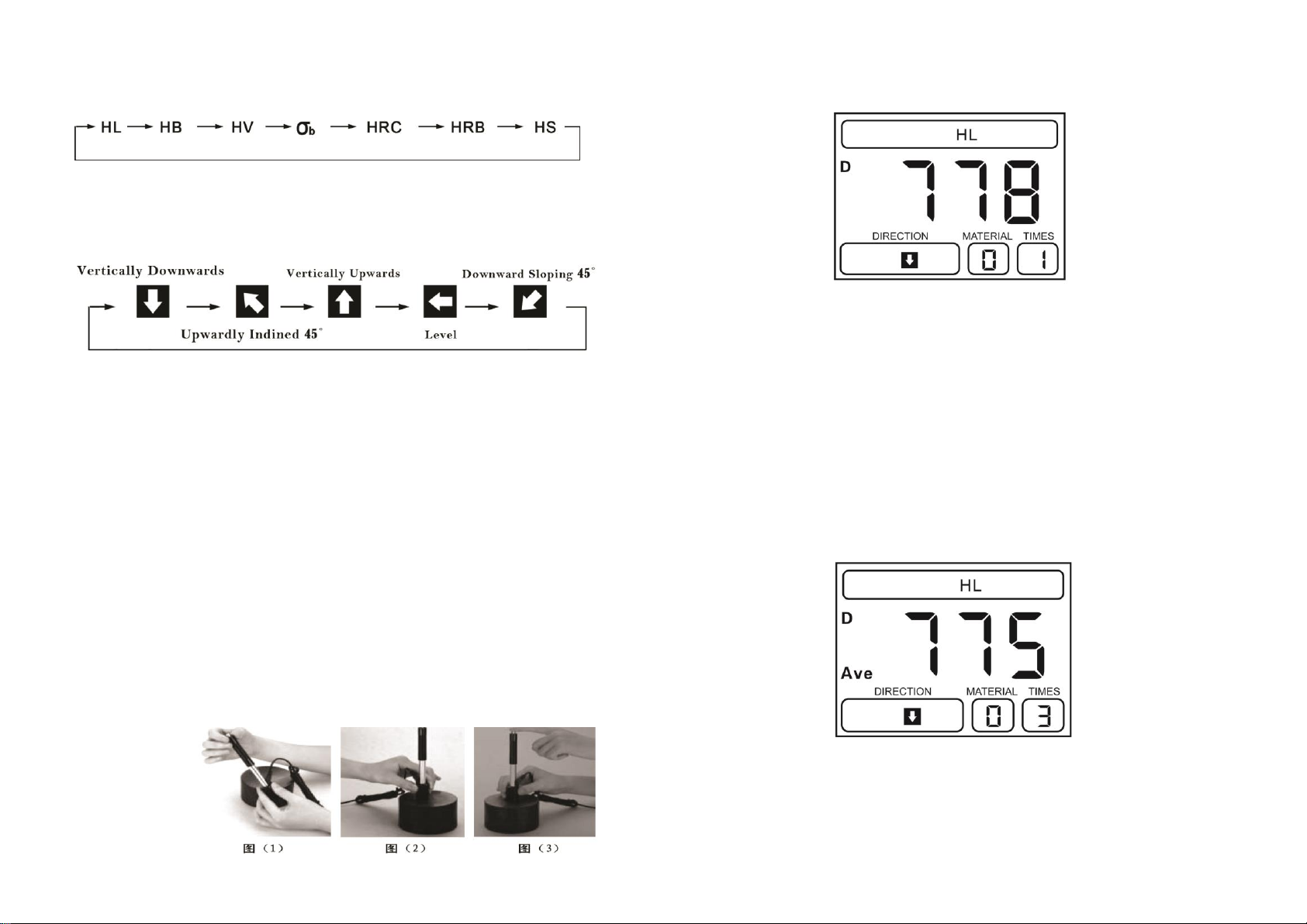
Hardness Scale: HL, HB, HRB,HRC,HV,HS, σb.
Measuring Range : HLD (200-960) HRC(19.8-68.5)HB(30-651)HV
(80-976)HS(26.4-99.5)HRB(13.5-100)σb(375-2639).
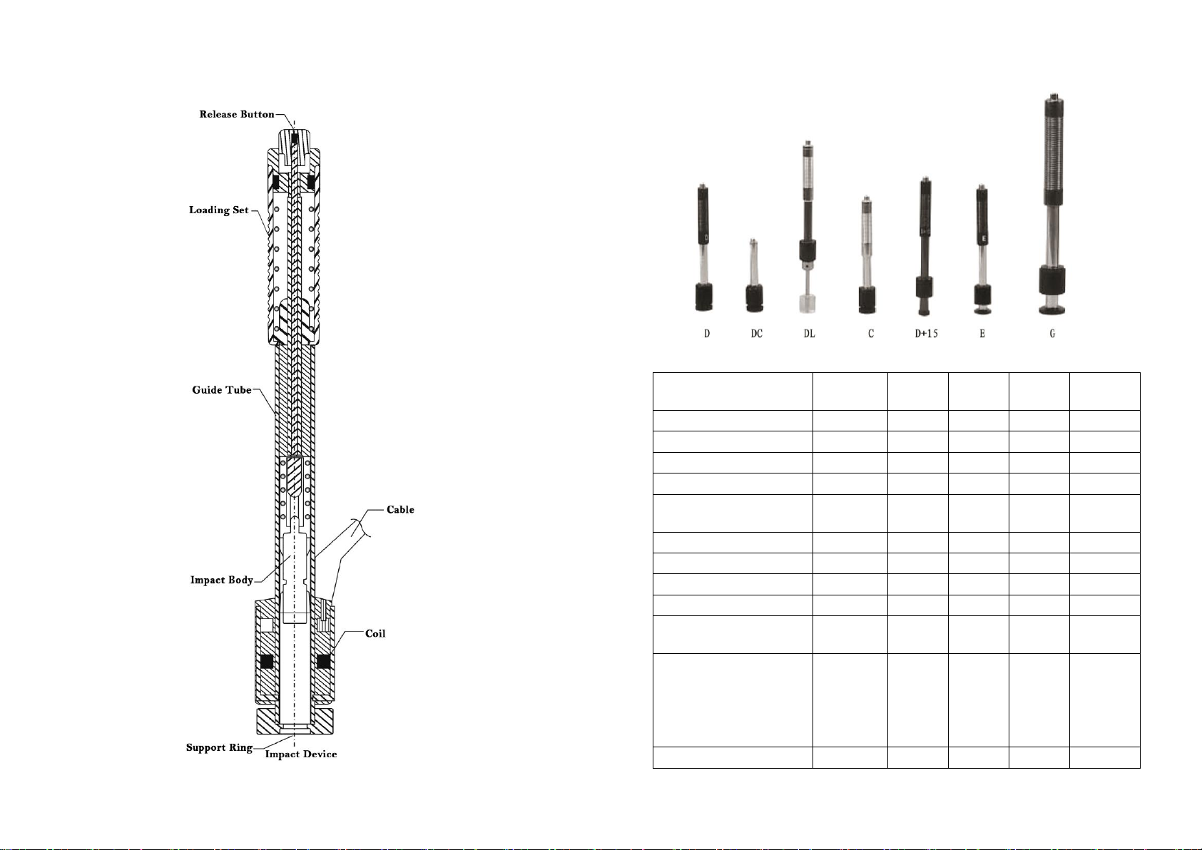
Impact device: D type impact device (Standard); Optional C/G/DC/DL/D+15
Accuracy: <±6HLD (HLD=800), Repeatability 6HLD (HLD=800)
Measuring direction: 360 degree by manual setting
Material : Steel& Cast Steel, Stainless Steel, GC IRON, NC IRON, Cast
Aluminum alloy, Macht metal, Copper-tin alloy, Brass
Resolution: 1HL, 1HV, 1HB, 0.1HRB, 0.1HRC, 0.1HS
Display: LED with backlight.
Memory: 100 groups (each group include 1-7 testing result and 1AVE value)
Communication: USB port (Standard) and Blue tooth (Optional)
Printer: Thermal Printer with blue tooth (optional)
Power: 2 AA batteries
Working temperature: -10℃~ +50℃
Size: 153 ×76×37 (mm) (H×W×D)
Weight: 280g include batteries
Standard: GB/T 17394-2014,ASTMA956
Warranty: 12 months after purchase
3.2 Applications
Installed machinery and Permanent assembly parts
Mould cavity
Heavy workpieces
Failure analysis of pressure vessel, turbine and other equipments
Small test area
The production line of Bearings and other parts
Distinguish the material of the metal material warehouse
4 .Pre-Treatment of Workpiece
4.1 Workpiece Requirements
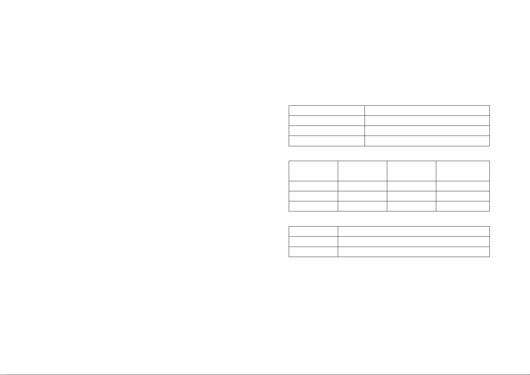
4.1.1 Surface Roughness requirements
Surface roughness is an important requirement for the surface of the test piece,
it should be smooth and no oil, or will cause measurement errors.
The surface roughness requirements are listed in table 4.1
Work piece surface roughness Ra
4.1.2 Weight and Thickness Requirements
Min thickness
(no coupling)
4.1.3 Surface Hardened Layer
Min. depth of surface hardened layer(mm)
4.1.4 Curved surface Requirement
Curved surface: The best testing surface of sample is flat. When the curvature
radius R of the surface to be tested is smaller than 30mm (D, DC, D+15, C, E
and DL type of impact device) and smaller than 50mm (G type of impact
device), the small support ring or the special support rings should be chosen.