YUSHI LM-100 User manual

Leeb Hardness Tester
LM100
Operating Manual
YUSHI INSTRUMENTS

CONTENTS
1. Principle of Leeb Hardness Testing Method...............................1
2. Instrument and Impact Device Diagram.......................................2
2.1 Instrument Diagram.....................................................................2
2.2 D Type Impact Device Diagram...................................................3
2.3 Types of Impact Device................................................................4
2.4 Impact Devices Specification.......................................................4
2.5 Standard Configuration................................................................6
2.6 Optional Accessories....................................................................6
3. Functions and Applications..............................................................7
3.1 Technical Specifications...............................................................7
3.2 Applications..................................................................................8
4.Pre-Treatment of Workpiece............................................................8
4.1 Workpiece Requirements..............................................................8
4.1.1 Surface Roughness Requirements.....................................8
4.1.2 Weight and Thickness Requirements.................................9
4.1.3 Surface Hardened Layer Thickness...................................9
4.1.4 Curved Surface Requirement............................................9
4.2 Support of Test Piece................................................................. 10
5. Operation............................................................................................10
5.1 Display........................................................................................10
5.2 Keyboard.....................................................................................11
5.3 Turn on the Instrument.............................................................. .11
5.4 Parameters Setting.......................................................................11
5.4.1 Material.............................................................................11
5.4.2 Hardness Scale..................................................................12
5.4.3 Impact Devices..................................................................12
5.4.4 Impact Direction................................................................12
5.4.5 Impact Times.....................................................................12
5.5 Measuring.....................................................................................12
5.5.1Operating............................................................................12
5.5.2 Delete the Gross Error Value.............................................13
5.6 Average Value...............................................................................13
5.7 Data Save and Read Setting ........................................................14
5.7.1 Storage Testing Result.......................................................14
5.7.2 Reading..............................................................................14
5.7.3 Delete.................................................................................15
5.7.4 Data Transmission..............................................................15
5.8 Bluetooth and Print........................................................................15
5.9 Calibration.....................................................................................15
6. Maintenance & Servicing..................................................................16
6.1 Clean the Impact Device .............................................................16
6.2 Servicing........................................................................................16

1.Principle of Leeb Hardness Testing Method
The impact body, which is equipped with tungsten carbide, impacts into the
work piece and rebounds back. The rebound and impact velocities are
measured at the 1mm point from the work piece in the following way: the
integrated permanent magnet will produce directly proportional voltage
with the impact velocity. The Leeb hardness values are calculated by the
following formula:
HL=1000×( Vb/ Va)
In Which:HL: Leeb hardness values
Vb: the voltage produced during the rebound of impact body
Va: the voltage produced during the impact of impact body
Figure 1 shows the voltage produced during the impact and rebound of
impact body:
voltage features of output signal
Figure 1.1
2. Instrument and Impact Device Diagram
2.1 Instrument Diagram
图2.1
Figure 2.1
1 2

2.2 D Type Impact Device Diagram
图 2.2
Figure 2.2
2.3 Types of Impact Device
Figure 2.3
2.4 Impact Devices Specification:
Special Impact
Device
D/DC/DL
D+15
C
G
E
Impact Energy
11mJ
11mJ
11mJ
11mJ
11mJ
Mass of Impact Body
5.5g/7.2g
7.8g
3.0g
20.0g
5.5g
Test Tip Hardness
1600HV
1600HV
1600HV
1600HV
5000HV
Test Tip Diameter
3mm
3mm
3mm
5mm
3mm
Test Tip Material
Tungsten
Carbide
Tungsten
Carbide
Tungsten
Carbide
Tungsten
Carbide
Tungsten
Carbide
Impact.Device Diameter
20mm
20mm
20mm
30mm
20mm
Impact Device Length
86/147/75
162mm
141mm
254mm
155mm
Impact Device Weight
50g
80g
75g
250g
80g
Max.Hardness of
Sample
940HV
940HV
1000HV
650HV
1200HV
3 4

Average Surface
Roughness Ra:
1.6μm
1.6μm
0.4μm
6.3μm
1.6μm
Min.Weight.of
Sample:(kg)
Directly Measurable
Need Stable Support
Tightly Coupled
>5
2-5
0.05-2
>5
2-5
0.05-2
>1.5
0.5-1.5
0.02-0.5
>15
5-15
0.5-5
>5
2-5
0.05-2
Min.Thickness.of
Sample:
Tightly Coupled
Min.Depth.of
Hardnes Layers
5mm
》0.8mm
5mm
》0.8mm
1mm
》0.2mm
10mm
》1.2mm
5mm
》0.8mm
Indentation Dimension of Test Tip
With
300HV
Diameter
0.54mm
0.54mm
0.38mm
1.03mm
0.54mm
Depth
24μm
24μm
12μm
53μm
24μm
With
600HV
Diameter
0.54mm
0.54mm
0.32mm
0.90mm
0.54mm
Depth
17μm
17μm
8μm
41μm
17μm
With
800HV
Diameter
0.35mm
0.35mm
0.35mm
--
0.35mm
Depth
10μm
10μm
7μm
--
10μm
Impact Device Applicable Scope
DC
Used for very confined spaces such as holes, cylinders
internal measurement
DL
Used for extremely confined spaces.
D+15
Used for measuring in grooves, recessed surface.
C
Used for testing case hardened or thin walled components.
G
Used for solid heavy component, such as rough castings and
forgings.
E
Used for high hardness material.
Table 2.1
2.5 Standard Configuration
LM100 Main Unit
D type Impact Device
HLD Value Standard Test Block
DataView Software
USB Communication Cable
Small Supporting Ring
Cleaning Brush
2 AA Battery
Operation Manual
Rubber Sheath
Instrument Case
2.6 Optional Accessories
Impact Device: C/G/DC/DL/D+15
Standard Test Block
Bluetooth Printer
Belt
Standard Supporting Ring
Small Supporting Ring
Special Supporting Rings ( See table 2.2 )
5 6
6

No.
Code
Model
Special
Support Ring
Sketch
Remark
1
03-03.7
Z10-15
Measure outside the cylindrical
surface R10~R15
2
03-03.8
Z14.5-30
Measure outside the cylindrical
surface R14.5~R30
3
03-03.9
Z25-50
Measure outside the cylindrical
surface R25~R50
4
03-03.10
HZ11-13
Measure inside the cylindrical
surface R11~R13
5
03-03.11
HZ12.5-17
Measure inside the cylindrical
surface R12.5~R17
6
03-03.12
HZ16.5-30
Measure inside the cylindrical
surface R16.5~R30
7
03-03.13
K10-15
Measure outside the spherical
surface SR10~SR15
8
03-03.14
K14.5-30
Measure outside the spherical
surface SR14.5~SR30
9
03-03.15
HK11-13
Measure inside the spherical
surface SR11~SR13
10
03-03.16
HK12.5-17
Measure outside the spherical
surface SR12.5~SR17
11
03-03.17
HK16.5-30
Measure outside the spherical
surface SR16.5~SR30
12
03-03.18
UN
Measure outside the cylindrical
surface,adjustable radius R10~
∞
Table 2.2
3. Functions and Applications
3.1 Technical Specifications
Measuring Method: Leeb Hardness Testing method
Hardness Scale: HL, HB, HRB,HRC,HV,HS, σb.
Measuring Range : HLD (200-960), HRC(19.8-68.5), HB(30-651), HV
(80-976), HS(26.4-99.5)HRB(13.5-100 ), σb(375-2639).
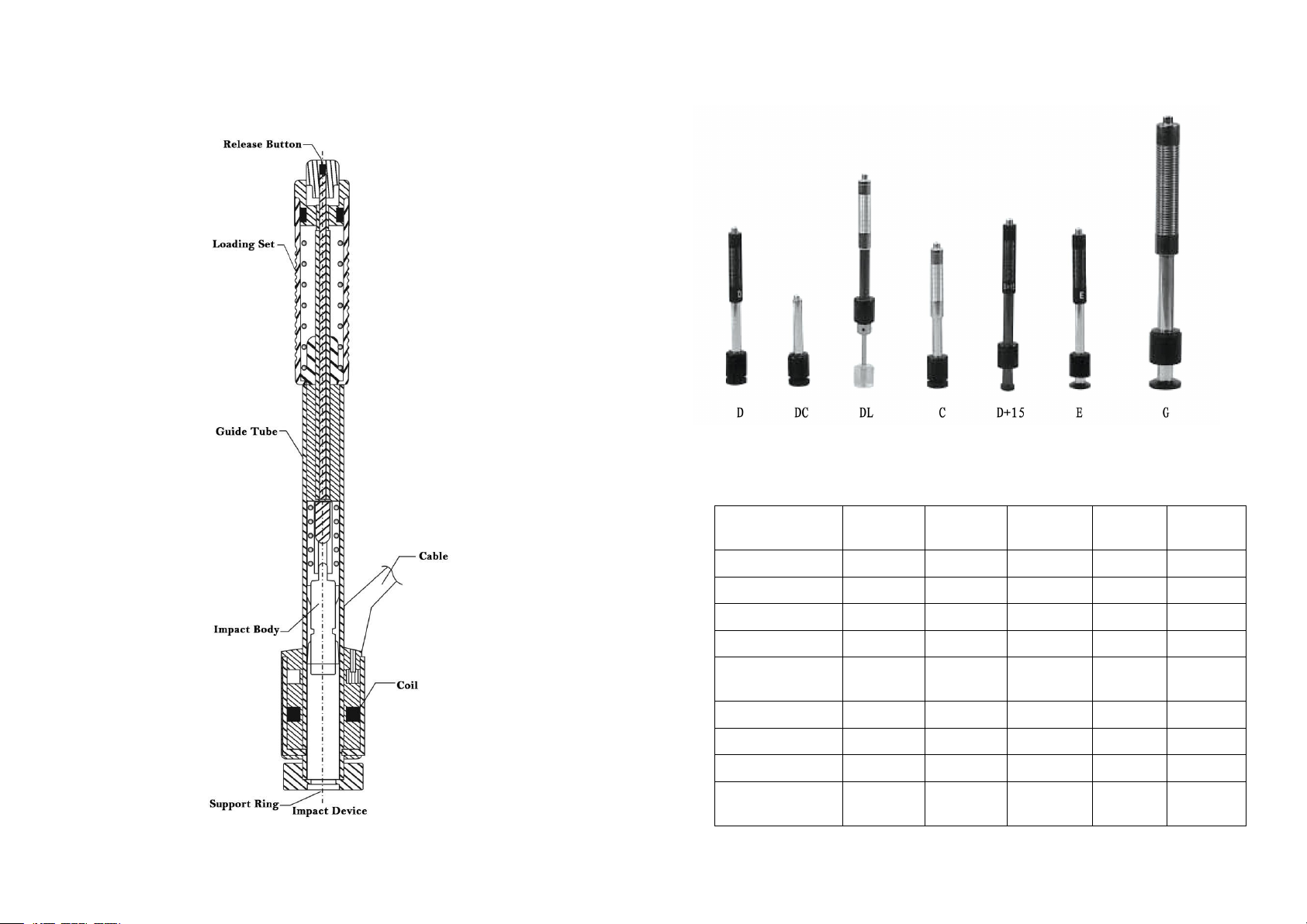
Impact Device: D type impact device (Standard); Optional
C/G/DC/DL/D+15
Accuracy: ±6HLD (HLD=800), Repeatability 6HLD (HLD=800)
Measuring Direction: Vertically downward, inclined downward, Level,
inclined upward, vertically upward
Material : Steel & Cast Steel, Stainless Steel, GC IRON, NC IRON, Cast
Aluminum Alloy, Copper-Zinc Alloy, Copper-Tin Alloy, Brass, Forging Steel.
Resolution: 1HL, 1HV, 1HB, 0.1HRB, 0.1HRC, 0.1HS
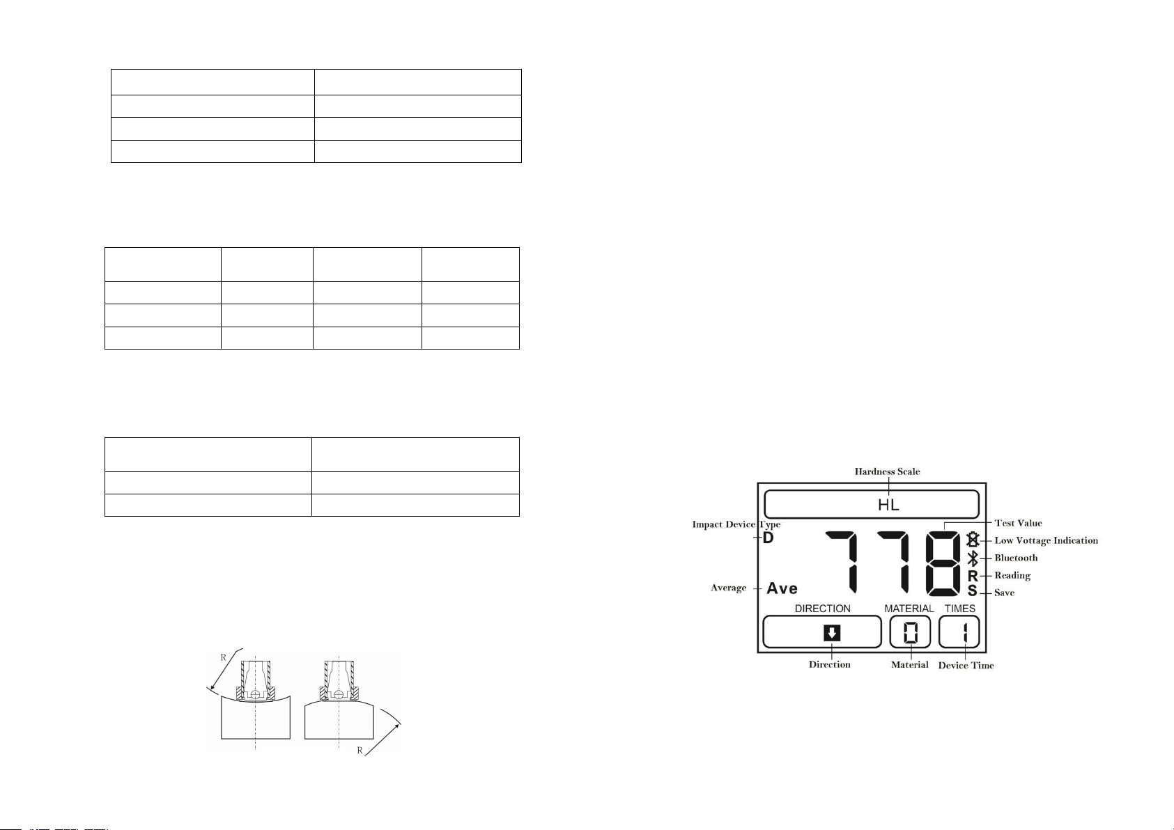
Display: High Contrast Segment Liquid Crystal Display (LED Backlight)
Memory: 100 groups ( impact times 1-7 )
Communication Port : USB 2.0 (Standard), and Bluetooth (Optional)
Printer: Thermal Printer with bluetooth (Optional)
Power: 2 AA batteries,1.5V
Working Temperature: -10℃~ +50℃
Size: 153 × 76×37 (mm) (H×W×D)
Weight: 280g ( include battery)
Standard: GB/T 17394-2014, ASTM A956
3.2 Applications
Installed machinery and Permanent assembly parts
Mould cavity
Heavy workpieces
Failure analysis of pressure vessel, turbine and other equipments
Small test area
The production line of Bearings and other parts
Distinguish the material of the metal material warehouse
4 .Pre-Treatment of Workpiece
4.1 Workpiece Requirements
4.1.1 Surface Roughness requirements
Surface roughness is an important requirement for the surface of the test
piece, it should be smooth and no oil, or will cause measurement errors.
The surface roughness of the test piece should not exceed the value in the
bellowing table:
7 8
8

Table 4.1
4.1.2 Weight and Thickness Requirements
The requirements of different types of impact devices for the quality and
thickness of the test piece in the following table:
Impact Device
Type
Min weight
Min thickness
(no coupling)
Min thickness
(coupling)
D、DC、DL、D + 15
0.05~2.0
2.0~5.0
>5.0
G
0.5~5.0
5.0~15.0
>15.0
C
0.02~0.5
0.5~1.5
>1.5
Table 4.2
4.1.3 Surface Hardened Layer Thickness
The requirements of the thickness of the hardened layer on the surface of
the test piece in the following table:
Impact Device Type
Min. Thickness of Surface
Hardened Layer(mm)
D、DC、DL、D + 15
0.8
C
0.2
Table 4.3
4.1.4 Curved Surface Requirements
Curved surface: The best testing surface of sample is flat. When the
curvature radius R of the surface to be tested is smaller than 30mm (D, DC,
D+15, C, E and DL type of impact device) and smaller than 50mm (G type
of impact device), the small support ring or the special support rings should
be selected.
4.2 Support of Test Piece
The heavy workpiece do not need support.
The Mid-heavy workpiece must be placed on a flat, sturdy surface, and
absolutely smooth placement, without any shaking.
Light workpiece must be tightly coupled with the solid support body,
the coupling surface must be smooth, and coupled dosages don’t too
much, Test direction must be perpendicular to the coupling surface.
When the workpiece is a large area of Sheet, Pole and Bending
Parts, Even if a large weight and thickness may still cause deformation,
so reinforcement and support in the rear surface of the test point is
necessary.
5. Operation
5.1 Display
Figure 5.1
Impact Device Type
Workpiece Surface Roughness Ra
D、 DC、DL 、D + 15
2 μm
G
7 μm
C
0.4 μm
9 10
Figure 4.1

5.2Keyboard
Figure 5.2
5.3Turn on the Instrument
Press to power on the LM100, the screen will display the default
interface for the first time, then power on again will display the last
parameters automatically.
5.4Parameters Setting
5.4.1 Material Setting
Press “MTL” button to select the material, material Code No. from 0-9, see
the following table:
Code
Hardness
Tensile strength
0
Steel and Cast Steel
C
1
GC. IRON
CrNi
2
NC. IRON
CrMo
3
C. ALUM
CrV
4
BRASS
CrMnSi
5
BRONZE
SSST
6
COPPER
SST
7
SST
CrNiMo
8
Forging Steel
Cr
9
Alloy Tool Steel
5.4.2 Hardness Scale Setting
Press “HD” button to select the hardness scale and strength.
Figure 5.3
5.4.3 Impact Devices
Press “Probe” button to select the probes.
5.4.4 Impact Direction
Press “DIR” button to select impact direction.
Figure 5.4
5.4.5 Impact Times
Press “TIME” button to set the impact times from 1-7, which will calculate
the average value after the certain times.
5.5 Measuring
5.5.1 Operating
After finish the parameters setting, then start measuring:
Load the impact body: Pushing the loading-tube until contact is felt.
Then allow it to slowly return to the starting position locking the
impact body. (see Figure 1)
Fixed position: Press the impact device support ring firmly on the
surface of the sample. (see Figure 2)
Release the impact body: Press the release button on the upside of the
impact device to test. The sample and the impact device as well as the
operator are all required to be stable now. The impact direction should
be vertical to the testing surface. (see Figure 3)
Table 5.1
11 12

Figure 5.5
After testing, the tester will display as following:
Figure 5.6
5.5.2 Delete the Gross Error Value
During the measuring process, if the deviation between the measured value
and standard value is too big before the mean value displaying, the current
measured value can be deleted by press “DEL” button, and the current value
would be neither stored nor in averaging, the impact times minus one.
5.6 Average Value
Normally, the measurements should be the average value of 3-5 times
testing results.After setting the impact times, the impact times reach the
setting value, will display the average value and the symbol “Ave”.The
interface of the average value as following:
Figure 5.7
5.7 Data Save and Read Setting
5.7.1 Storage Testing Result
Press “MEM” storage button to set the saving function, the “S” symbol will
be shown on the display.
The tester will save the testing results automatically, including 7 testing
results and 1 average value each group, and total 100 groups can be stored.
After storing a group, the storage flag is off.
(Note: During the current group test, before the average value is displayed,
press “MEM” storage button to store the group of data)
5.7.2 Reading
In saving status, press and hold “MEM” storage button to enter the reading
mode and the symbol “R”will be shown on the display (see Figure 5.8).
At the same time, the first impact value in the recently saved groups will be
displayed, press “up”and “down”button to read the saved testing
value.Then press (or long press) “MEM” storage button to quit the mode of
reading, and the symbol “R”off.
13 14
Figure 5.8
13 14

5.7.3 Delete
Press “DEL” button in reading mode to delete one group data. Long press
“DEL” button to delete all stored values.
5.7.4 Data Transmission
The data in stored can be transferred from the instrument to a PC via
communication software, to save, statistic and analyze the measurement.
(See the help documentation in communication software for details)
5.8 Bluetooth and Print (Optional )
After completing a set of tests and displaying the average value, press the
“Bluetooth” button, the Bluetooth symbol flashes, and the instrument
starts to pair the printer automatically. After connecting successfully, the
Bluetooth symbol will be shown on the display (see Figure 5.9). The header
will be printed automatically, when the printer is successfully connected for
the first time, and then the measured value and average value will be
printed. When complete a set of tests each time, press the "Bluetooth"
button to print this set of values, then the Bluetooth symbol will be off.
图 5.9
5.9 Calibration
After a long time of using, the test tip on the impact device will has abrasion,
this will cause the measuring error, so we design a calibration procedure of
using the standard testing block to calibrate.
Press“up”and“down”button at the same time after the power on, then
the tester will enter calibration mode, the identification of calibration
displays. Then impact the standard block with the impact device,
measure 1-7 times selectable to get the average value, then press “up”and
“down”button to adjust the measured value to the standard value, finally
press the “save” button to finish the calibration,the instrument will save the
calibrated data and exit the calibration mode. If you want to give up the
calibration, please press the “power off ”button directly in calibration
mode.
Figure 5.10
6.Maintenance & Servicing
6.1 Cleaning of Impact Device
After long time using, please use the cleaning brush to clean the tube and
impact body.
Unscrew the support ring , take out the impact body.
Spiral the nylon brush in counter-clock direction into the bottom of the
tube and pull it out, repeat many times.
Install the impact body and support ring.
Release the impact body after testing every times.
6.2 Servicing
Leeb hardness tester is a high-tech product, maintenance work should be
operated by professionals, please do not operate by yourself.
15 16
Figure 5.9
Other manuals for LM-100
1
Table of contents
Other YUSHI Test Equipment manuals