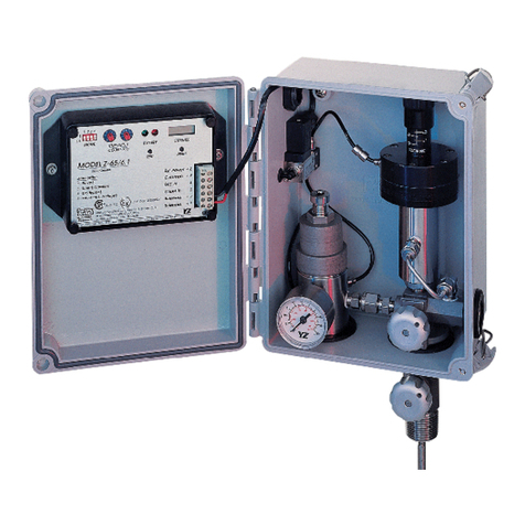
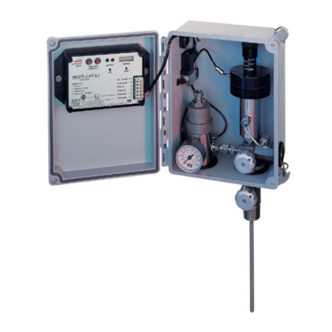
YZ Systems DynaPak DP-2010 Parts list manual

DynaPak Gas Sampler
S Y S T E M S U P P O R T M A N U A L
DP-2010
Versions: D, F, J, K, L, STD

DP-2010
InstructIon &oPeratIng
Manual
Version: 05-2018

YZ Systems Milton Roy • 201 Ivyland Road • Ivyland, Pennsylvania • USA • 18974 • P: 281.362.6500 • www.yzsystems.com
DP-2010 ver.05-2018 Page i
DP-2010 Table of ConTenTs
Section 1: First Things To Know.................................................................................................................1
How to Use this Manual..................................................................................................................................1
Typographic Conventions................................................................................................................................1
Getting Help....................................................................................................................................................1
Operation Specications.................................................................................................................................2
Theory of Operation........................................................................................................................................2
System Accessories........................................................................................................................................3
Section 2: System Installation.....................................................................................................................4
Standard System Components.......................................................................................................................4
System Flow Schematic..................................................................................................................................5
Standard Mounting Location...........................................................................................................................6
Standard System Connections.......................................................................................................................7
Section 3: Sample Vessel Installation........................................................................................................8
Variable Pressure/Constant Volume Cylinders.............................................................................................8
Variable Volume/Constant Pressure cylinder...............................................................................................8
Section 4: System Control & Electronics................................................................................................9
Overview.....................................................................................................................................................9
Section 5: Programming for Proportional-to-Flow Operation................................................................10
Setting Operator Input Values.......................................................................................................................10
Section 6: Programming For Proportional-To-Time Operation..............................................................12
Section 7: Mechanical System..................................................................................................................13
DP-2000 Sample Pump................................................................................................................................14
YZ Filter Regulator.......................................................................................................................................14
Section 8: System Operation......................................................................................................................15
Preparing The System for Operation..............................................................................................................15

YZ Systems Milton Roy • 201 Ivyland Road • Ivyland, Pennsylvania • USA • 18974 • P: 281.362.6500 • www.yzsystems.com
DP-2010 ver.05-2018
Page ii
Section 9: System Maintenance.............................................................................................................16
Preventative Maintenance Schedule...........................................................................................................16
RecommendedSparePartsList....................................................................................................................16
Cleaning and lubricating the DP-2000 pump...............................................................................................17
Replacing a Depleted Battery......................................................................................................................19
Section 10: System Troubleshooting......................................................................................................20
How to Use This Section.............................................................................................................................20
For Additional Help...............................................................................................................................20
Step-by-Step Resolution.......................................................................................................................20
Battery Power..............................................................................................................................................21
Battery Power Troubleshooting Steps...................................................................................................21
Proportional-to-Flow Mode.....................................................................................................................................22
Proportional-to-Flow Mode Troubleshooting Steps..............................................................................22
Proportional-to-Time Mode..........................................................................................................................23
Proportional-to-Time Mode Troubleshooting Steps.............................................................................23
Appendix A: Illustrations.........................................................................................................................25
DynaPak 2000 Pump, Assembled..............................................................................................................25
DynaPak 2000 Pump, Exploded View.........................................................................................................26
DynaPak 2000 Pump, List of Parts............................................................................................................27
YZ Filter Regulator Assembly.....................................................................................................................28
YZ Filter Regulator, Exploded View............................................................................................................29
Link Plus......................................................................................................................................................30
DuraSite Sample Vessel..............................................................................................................................31
Z-65 and Solenoid.......................................................................................................................................32
Z-65 Wiring Control Document....................................................................................................................33

YZ Systems Milton Roy • 201 Ivyland Road • Ivyland, Pennsylvania • USA • 18974 • P: 281.362.6500 • www.yzsystems.com
DP-2010 ver.05-2018
Page 1
seCTion 1: firsT Things ToKnow abouT The DynaPaK
How to Use this Manual
The DP-2010 Operations Manual is a step-by-
step guide containing the procedures needed to
work with the DP-2010 System.
The DynaPak System Series of samplers imple-
ment the most advanced technology available in
the industry. It is recommended that the techni-
cians working with the DynaPak Systems study
the manual prior to initiating work on the system
for the rst time.
Typographic Conventions
To aid in readability, this manual uses several
typographic conventions. References to illustra-
tions, photographs, and other related content will
appear in italicized text along with the location
of where to nd the item in the manual. Digi-
tal versions of the manual, available in Adobe
Acrobat™ PDF format, will be highlighted further
in blue italic text indicating the copy retains a
hyperlink to the referenced item.
Measurement units are listed in italic parenthe-
sis text following their US standard equivalent.
As an example, for dening a distance, 15′ (4.5
meters), is how the text will appear throughout
the manual.
Items that require action, for example the press-
ing of a key for programming the controller, will
feature the action item in sentence case Bold
Text followed in normal text by the item such as,
the Up Arrow key or Main Power switch.
Getting Help
This manual provides solutions to typical ques-
tions about the DP-2010 system. If the answer
can not be found within this manual, contact YZ
Systems at:
T: 1.281.362.6500
T: 1.800.653.9435
When calling, have this manual close at hand.
Whether calling or writing, please include in your
communique the following information:
• The serial number of the DynaPak System and
the version number of this manual. The serial
number is located on the inside of the enclosure
door. The version number of this manual is
located at the bottom of each page.
• A description of the problem and, if applicable
the actions of the technical personnel when
the problem occurred.

YZ Systems Milton Roy • 201 Ivyland Road • Ivyland, Pennsylvania • USA • 18974 • P: 281.362.6500 • www.yzsystems.com
DP-2010 ver.05-2018
Page 2
seCTion 1: firsT Things ToKnow abouT The DynaPaK
Operation Specications
Maximum Output: 5,760 cc/day
(5.76 liters/day)
Maximum Operating Pressure: 1,500 psig
(124 Bar (g))
Pump Displacement: .2 - .4 cc/Stroke
Operating Temp Range: 0 to 140 degrees F.
(17˚C to 60˚C)
Power Supply: Internal Battery Pack
Flow Signal: Dry Contact or
Voltage Pulse
Theory of Operation
The DynaPak 2010 Sampler is a pipeline
mounted system which uses the pneumatically
operated, positive displacement DynaPak 2000
pump, the Z-65 timer/controller, the YZ lter/reg-
ulator and a low power solenoid valve to obtain
gas samples. The 2010 provides two modes
of operation:
A. Time-based sampling:
In this mode of operation, the 2010 extracts a
gas sample from the pipeline at regular time in-
tervals. The volume of the sample is set by the
operator using the volume adjustment feature of
the DP-2000 pump. The Z-65 controller oper-
ates as a recycling timer, periodically energizing
a low power solenoid valve. Energizing the so-
lenoid valve allows actuation gas to stroke the
DP-2000 pump. The rate at which this occurs
is a function of operator input. Two 10 position
switches are used to set the off time interval.
The number of times the solenoid output is ac-
tivated is recorded by the onboard LCD stroke
indicator.
B. Proportional-to-Flow sampling:
In this mode of operation, the Z-65 counter
operates as a dividing counter. The Z-65 coun-
ter periodically energizes a low power solenoid
valve. As in the time-based mode of operation,
this allows actuation gas to stroke the DP-2000
pump. The rate at which this occurs is a function
of operator input as well as the host computer
or other device that inputs pulses per volume
metered. The two 10-position switches on the
Z-65 are used to set the number of pulses the
counter will count before activating the solenoid
output. The number of times the solenoid output
is activated is recorded by the onboard LCD
stroke indicator. Sample volume is again con-
trolled using the DP-2000 volume adjustment
knob.
In both modes of operation, the Z-65 timer/
counter operates using a replaceable internal
battery pack. The battery pack condition is
monitored by way of two indicator LEDs. When
the battery pack needs replacement, the red
LED will illuminate when the solenoid output is
activated. If the battery pack is good, the green
LED will illuminate when the solenoid is acti-
vated.
YZ Systems Milton Roy • 201 Ivyland Road • Ivyland, Pennsylvania • USA • 18974 • P: 281.362.6500 • www.yzsystems.com
DP-2010 ver.05-2018 Page 3
seCTion 1: firsT Things ToKnow abouT The DynaPaK
System Accessories
• The External Power Option can be used in lieu of
the internal battery pack. The External Power Option
(model # EPO-120) consists of an AC to DC convertor
and intrinsically safe barrier to convert 120 VAC power
to 28 VDC to operate the controller without the use of
the internal battery pack.
• The Solar Power Option would be used in lieu of
the internal battery pack. The Solar Power Option
(model #SPO-120) consists of a 5 watt solar panel with
RM-12 charger regulator module and internal 12V, 5
Amp hour battery pack.
• DuraSite, portable DOT approved constant pressure
sample vessels. Available in 150, 300, 500, 800, and
1000 cc sizes.
• SC-Spun Vessel, portable DOT approved (1800 psi
maximum working pressure), sample vessels. Avail-
able in 300, 500, and 1000 cc sizes.
• KK-1, KK-2, & KK-3: carrying cases for DuraSites
that meet DOT requirements for transporting portable
sample vessels.
• 1/4″ stainless steel tubing Dielectric Isolator Union.
These should be installed in every tubing line that at-
taches the sampler to the pipeline in any manner. For
example the supply gas, product connection to the
system, and differential pressure switch connections.
(P/N A1-0182).
• LinkPlus provides a direct link between the Dy-
naPak, and your sample vessel, providing a gauge,
vessel isolation valve, and excess pressure protection.
• YZ BackRack vessel trays are available for direct
support mounting of a sample vessel tray to the back
of the DynaPak. Limited to SC-300 & SC-500 Vessels.
NOTE: A complete line of sampling accessories rang-
ing from sample probes to sample vessels is available
through YZ. Please contact your local representative or
YZ toll free at 800.344.5399. For technical support call
800.653.9435.

YZ Systems Milton Roy • 201 Ivyland Road • Ivyland, Pennsylvania • USA • 18974 • P: 281.362.6500 • www.yzsystems.com
DP-2010 ver.05-2018
Page 4
seCTion 2: sysTem insTallaTion
Standard System Components
Standard primary components of the DynaPak
2010 include the following:
• System Enclosure: Houses the Sample
Pump, Filter Regulator, Solenoid, and Controller.
• Sample Pump: Probe mounted, pneumatically
actuated DP-2000 Sample Pump.
• Filter Regulator: Stainless Steel regulator ca-
pable of reducing pressure from line pressure of
up to 1500 psi down to system supply pressures
in one step.
• Low Power Solenoid: Provides interface
between the Z-65 Electronic Controller, and the
Pump Pneumatic actuation.
• Controller: Provides control functions for the
DynaPak Sampler in Proportional-To-ow, or
Proportional-To-Time Modes.
• Probe Body Assembly: Provides direct mount
connection to the pipeline.
gure 1

YZ Systems Milton Roy • 201 Ivyland Road • Ivyland, Pennsylvania • USA • 18974 • P: 281.362.6500 • www.yzsystems.com
DP-2010 ver.05-2018 Page 5
seCTion 2: sysTem insTallaTion
System Flow Schematic
gure 2
(EPO-120)
(SPO-120)

YZ Systems Milton Roy • 201 Ivyland Road • Ivyland, Pennsylvania • USA • 18974 • P: 281.362.6500 • www.yzsystems.com
DP-2010 ver.05-2018
Page 6
seCTion 2: sysTem insTallaTion
Standard Mounting Location
1. The sampler should be a minimum of ve pipe
diameters from any device which could cause
aerosols or signicant pressure drops.
2. The sampler should not be located within the
dened meter tube region (AGA 3 manual).
A= The number of unobstructed, straight pipe
diameters upstream (see AGA – 3 manual).
B= the number of unobstructed, straight pipe
diameters downstream (see AGA - manual).
A= The number of unobstructed, straight pipe
diameters upstream (see AGA – 3 manual).
B= The number of unobstructed, straight pipe
diameters downstream (see AGA – 3 manual).
gure 3

YZ Systems Milton Roy • 201 Ivyland Road • Ivyland, Pennsylvania • USA • 18974 • P: 281.362.6500 • www.yzsystems.com
DP-2010 ver.05-2018 Page 7
seCTion 2: sysTem insTallaTion
Standard System Connections
a. The DynaPak 2010 requires a 3/4” FNPT
pipeline connection (1/2” for J version).
b. The DynaPak 2010 sampler should be
mounted vertically in a horizontal run of the
pipeline.
c. The end of the sampler probe should
penetrate the center 1/3rd of the pipeline.
d. The end of the sample probe should be cut
parallel to the pipeline.
e. Before applying pipeline pressure to the
DynaPak 2010, ensure that the isolation
valve and purge valve are good.
f. After pipeline pressure has been applied to
the sampler, check the probe body/pipeline
connection using a liquid leak detector.
CAUTION: Overtightening of valves can re-
sult in damage to the valve components which
might result in the valve stem being screwed
out of the probe body. This, of course, results
in product at pipeline pressure being vented
continually through this port until this section of
the pipeline is shut in. DynaPak valves are of
soft seat design and should only be closed or
opened with ngers. Wrenches should never be
used. If a valve will not seal off with nger tight
operation the valve should have maintenance
performed to allow proper operation of the
valve.
gure 4
gure 5
NOTE: At temperatures below 32˚ F (0˚C), condi-
tioning of the actuation gas supply may be required.
Where the actuation gas supply has a high water
content and/or a low hydrocarbon dew point, addi-
tional actuation gas ltration or heating of the actua-
tion gas supply may be necessary. Bottled nitrogen
gas can also be used during cold operating condi-
tions to avoid condensation in the actuation gas sup-
ply line. In addition, operation at extreme tempera-
tures will affect seal and diaphragm performance.
To prolong the service of seals and diaphragm,
adequate heat should be provided to maintain an
operating environment above 32˚ F (0˚C).

YZ Systems Milton Roy • 201 Ivyland Road • Ivyland, Pennsylvania • USA • 18974 • P: 281.362.6500 • www.yzsystems.com
DP-2010 ver.05-2018
Page 8
seCTion 3: samPle Vessel insTallaTion
Variable Pressure / Constant Volume Cylinders
Spun cylinders may be installed in a horizontal
position on the DynaPak BackRack vessel rack.
Avoiding traps in the line, install stainless steel
tubing and ttings from the sample discharge port
of the sampler to the product end of the sample
cylinder.
300cc and 500cc spun cylinders may also be in-
stalled in a vertical position. Piping from the sam-
pler discharge port to the sample vessel should be
arranged so that liquid traps are not created.
Variable Volume / Constant Pressure cylinder
The free oating piston cylinder (DuraSite), gure
35 on page 31, may be installed in a horizontal
position on an optional vessel rack. Free oating
piston cylinders should NOT be installed on the
DynaPak BackRack vessel rack.
Install 1/8″ tubing from the sample discharge port
of the manifold to the product end of the vessel.
Avoid traps in this line.
LinkPlus: Install the optional LinkPlus directly into
the sample discharge port of the sampler. Use
stainless steel tubing and ttings to connect the
LinkPlus outlet to the product end of the sampler
cylinder.

YZ Systems Milton Roy • 201 Ivyland Road • Ivyland, Pennsylvania • USA • 18974 • P: 281.362.6500 • www.yzsystems.com
DP-2010 ver.05-2018 Page 9
seCTion 4: sysTem ConTrol &eleCTroniCs
Overview
The electronic control package provided with
your sampling system consists of a solid state
Controller, and a Low Powered Solenoid. The
controller energizes the solenoid which in turn
sends a pneumatic actuation signal to the Sam-
ple Pump, every time sample is required either
Proportional-To-Flow, or Time.
SAFETY NOTES
Always use extreme care when performing
maintenance on Sampling Systems. Always take
necessary measures to assure that electrical
classication in the area is considered, before,
and during all repairs, and that necessary steps
are taken to maintain proper electrical proce-
dures for the classication of the area.
The control package requires you to congure
the Z-65 controller to operate in a Proportional-
To-Flow mode, refer Section 5, to page 10, a
Proportional-To-Time mode, refer to Section 6,
page 12. All wiring connected to the controller
must be done in accordance with the Wiring
Control Document, refer to Appendix A, Figure
37, page 33. DynaPak electronics are rated
for use in Class I, Division 1, Groups C and D
hazardous locations.

YZ Systems Milton Roy • 201 Ivyland Road • Ivyland, Pennsylvania • USA • 18974 • P: 281.362.6500 • www.yzsystems.com
DP-2010 ver.05-2018
Page 10
seCTion 5: Programming for ProPorTional-To-flow oPeraTion
Setting Operator Input Values
In this mode of operation, the Z-65 controller is
used as a dividing counter to control the rate at
which the pump is actuated. The desired time
between pump strokes is controlled by the host
computer or output device that will give an input
pulse to the Z-65 controller.
1. Determine if the incoming input is either a,
dry contact or voltage pulse.
2. If the input is a dry contact:
a. Terminate the incoming connections to the
Z-65 terminal strip (see illustration).
b. Turn mode switches 1, 3 to ON and 2, 4 to
OFF.
OR
3. If the input is a voltage pulse:
a. Terminate the incoming connections to the
Z-65 terminal strip (see illustration).
b. Turn mode switches 1, 3, 4 to ON and switch
2 to OFF.
gure 6
gure 7
5-24 VDC
(Voltage pulse)
(20 msec
duration min.)
Dry contact or
open collector
(20 msec
duration min.)

YZ Systems Milton Roy • 201 Ivyland Road • Ivyland, Pennsylvania • USA • 18974 • P: 281.362.6500 • www.yzsystems.com
DP-2010 ver.05-2018 Page 11
seCTion 5:Programming for ProPorTional-To-flow oPeraTion
4. Calculate the counter setting using the following chart:
5. Adjust the pump volume adjustment knob to the value used in the calculation in step 4.
Sample pump displacement per stroke Number of turns open on the pump volume knob
.1cc 3
.2cc 6
.4cc 12
6. Turn the counter dials to the appropriate number of pulses you want to count before the
sample pump strokes.
7. Press the test button once to load the value
into the memory.
NOTE: If the calculated counter setting is less
than 1 or greater than 99, the pulses per volume
metered will need to be adjusted. This can be
programmed in most ow meters to the desired
rate. If the calculated counter setting is less than
1, increase the pulses per volume metered. If
the calculated counter setting is greater than 99,
decrease the pulses per volume metered.
gure 8
1. Your pump displacement (from .1 to .4cc’s) = a.
2. Your sample cylinder volume in cc’s (300cc, 500cc, etc.) = b.
3. Average ow rate (MMCF per day or MCM per day) = c.
4. Sample period in days = d.
5. Pulses/volume metered (pulses/MMCF or pulses/MCM) = e.
6. Counter setting = a x c x d x e
(b)
Example #1: Example #2
English Gas Flow Metric Gas Flow
Units Units
Pump displacement (a.) = .2cc .2cc
Sample cylinder size (b.) = 300cc 300cc
Average ow rate (c.) = 10 MMCF per day 10MCM/day
Sample period (d.) = 30 days 30 days
Pulses per volume metered (c.) = 100 pulses/MMCF 100 pulses/MCM
Example #1
Counter setting = .2cc x 10 MMCF per day x 30 days x 100 pulses per MMCF = 20 pulses
300 cc
Example #2
Counter setting = .2cc x 10 MCM per day x 30 days x 100 pulses per MCM = 20 pulses
300 cc
Example
20 pulses

YZ Systems Milton Roy • 201 Ivyland Road • Ivyland, Pennsylvania • USA • 18974 • P: 281.362.6500 • www.yzsystems.com
DP-2010 ver.05-2018
Page 12
seCTion 6: Programming for ProPorTional-To-Time oPeraTion
1. Calculate the sampling rate to ll a cylinder in 30 days:
2. Set the timer dials on the Z-65 to the sample rate
from step 1.
NOTE: To obtain maximum battery life, choose
the longest time interval and the largest pump
displacement setting possible.
NOTE: The time (18 minutes), in the chart
above, corresponds to the dial setting shown for
the Z-65 model with the timer range setting in
the factory position (jumper on the two left pins).
See section 10 Timer Range Setting, Page 24.
gure 9
Example
Number of
turns
open on pump
stroke knob
Sample
pump
displacement
per stroke
Sample cylinder volumes
1000 cc 500 cc 300 cc
3 .100 4 9 15
6 .200 9 18 30
9 .300 13 27 45
12 .400 18 36 60
Sample
rate
(minutes)
3. Adjust the pump volume adjustment knob to the value used in the calculations in step 1.
Sample pump displacement per stroke Number of turns open on the pump volume knob
.1cc 3
.2cc 6
.4cc 12
4. Turn mode switches 1, 2, 3 to ON and 4 to
OFF.
5. Press the test button once to initiate the
timer sequence.
gure 10

YZ Systems Milton Roy • 201 Ivyland Road • Ivyland, Pennsylvania • USA • 18974 • P: 281.362.6500 • www.yzsystems.com
DP-2010 ver.05-2018 Page 13
seCTion 7: meChaniCal sysTem
Overview
The DynaPak mechanical system as shown
below is composed of the sample pump, and
lter regulator. These components of the
system are shown here and described in the
following pages.
gure 11
(3/4” standard, 1/2” J version)

YZ Systems Milton Roy • 201 Ivyland Road • Ivyland, Pennsylvania • USA • 18974 • P: 281.362.6500 • www.yzsystems.com
DP-2010 ver.05-2018
Page 14
seCTion 7: meChaniCal sysTem
DP-2000 Sample Pump
DP-2000 Sample Pump, refer to Appen-
dix A, page 25, is a positive displacement
plunger pump. It’s robust design provides
for dependable sampling service, while also
providing a simple to maintain pump, with
few internal components. The pump has an
adjustable displacement of .1 to .4 cc per
stroke. The set displacement may be viewed
at the volume adjustment knob, refer to Ap-
pendix A, page 26, located on the top of the
DP-2000 pump. Adjustment is simple. Turn
the volume adjustment knob clockwise to
increase the pump volume displacement per
stroke, or turn the volume adjustment knob
counter clockwise to decrease the pump
volume displacement per stroke. Final con-
trol of the volume of sample to be gathered
during the sample cycle period, is achieved
by the controller.
This pump has internal pressure balancing
capabilities that allows the pump to func-
tion properly when the pipeline pressure is
greater than the sample vessel pressure, or
when the sample vessel pressure is greater
than the pipeline pressure.
Each time the pump strokes, product pre-
viously captured in the pump chamber is
forced towards the sample cylinder. As the
pump plunger returns to a resting state a
new fresh sample is captured in the pump.
Once the pump completes its stroke, the
cycle is ready to begin again.
Filter Regulator
The DynaPak Filter Regulator, refer to Ap-
pendix A, page 29, is a stainless steel ltered
regulator to supply the supply gas required
to actuate the sample pump. It is capable of
providing actuation pressure from pipeline
pressures to required actuation pressures in
a single dependable step.
Maintenance is minimal, but is certainly de-
pendant on gas quality. Should the gas sup-
plied to the lter regulator require signicant
ltration, replacement of the lter may be
more frequent than normal, refer to System
Maintenance, page 16.

YZ Systems Milton Roy • 201 Ivyland Road • Ivyland, Pennsylvania • USA • 18974 • P: 281.362.6500 • www.yzsystems.com
DP-2010 ver.05-2018 Page 15
seCTion 8: sysTem oPeraTion
Preparing The System for Operation
1. When all of the tubing connections have
been completed, close the purge valve on
the front of the sampler probe body. Open
the sample probe isolation valve to allow
pipeline pressure into the sampler, refer to
Section 7, page 13. Check all connections
using a liquid leak detector.
2. Adjust the lter/regulator from the following
ranges, refer to Section 7, page 14:
3. Turn the stroke adjustment knob on the top
of the pump counterclockwise to set the
pump displacement at .4 cc/stroke, refer to
Section 7, page 14.
4. Move all of the mode switches on the Z-65 to
their OFF positions as shown.
5. Move both timer/counter dials to the 0
position (00 minutes) as shown.
6. Move mode switches 1, 2 and 3 to ON
position. The pump will begin stroking once
every 2 seconds in a diagnostic test mode as
shown.
7. Allow the sampler to operate until the
pipeline pressure plus 100 psi (6.9 Bar) is
achieved at the sample discharge.
8. Return the mode switches to their OFF
positions as shown.
9. Check all connections from the sampler
discharge to the connection on the sample.
Pipeline Pressure Actuation Pressure
Under 700 psig (48 Bar) 50 psig (3.5 Bar)
Over 700 psig (48 Bar) 65 psig (4.5 Bar)
gure 12
gure 13
gure 14
gure 15
gure 16
NOTE: Black indicates
the switch position

YZ Systems Milton Roy • 201 Ivyland Road • Ivyland, Pennsylvania • USA • 18974 • P: 281.362.6500 • www.yzsystems.com
DP-2010 ver.05-2018
Page 16
seCTion 9: sysTem mainTenanCe
Preventative Maintenance
Schedule
A preventative maintenance program
serves to anticipate maintenance issues
prior to waiting until the system requires
service. Like changing the oil & lters in
an automobile, by choosing to service the
various parts and operation in the Sampling
System at regular intervals, the technician
can perform the maintenance service when
desired, rather than when required, such as
in the middle of night.
The key is to perform maintenance before it
is required. The preventative maintenance
schedule implemented should consider the
application of the sampler. Many of these
considerations include: the weather envi-
ronment; the condition of, the actuation gas,
the product condition and quality, and the
pump stroke frequency. All of these issues
must be considered when establishing a
preventative maintenance schedule.
Recommended Maintenance Schedule
Monthly Inspection
1. Verify system pressure
2. Check for leaks
3. Test the battery.
4. Test the system for leaks each time a
tting or connection has been made.
Semi-Annual Inspection
1. Clean and lubricate the sample pump
2. Check the lter element, and replacing
as necessary.
Annual Inspection
1. Rebuild pump
2. Test the Sampler System performance
and service, as needed
3. Replace Z-65 Battery Assembly.
Recommended Spare Parts List
Part # Description Recommended
Quantity
D3-0002 DP-2000 pump seal
replacement kit 1
D3-0003 Filter Regulator repair kit 1
A4-0001 Solenoid 1
E3-2001 Z-65 Battery Assembly 1
Table of contents
Other YZ Systems Sampler manuals

YZ Systems
YZ Systems DynaPak DP-2010JF Parts list manual

YZ Systems
YZ Systems DynaPak DP-2010RN Parts list manual

YZ Systems
YZ Systems DynaPak DP-2010UX Parts list manual

YZ Systems
YZ Systems DynaPak DP-2010FU Parts list manual

YZ Systems
YZ Systems DynaPak Series Installation instructions

YZ Systems
YZ Systems DynaPak DP-2010RXN Parts list manual

YZ Systems
YZ Systems DynaPak 2010N Series User manual