General Features
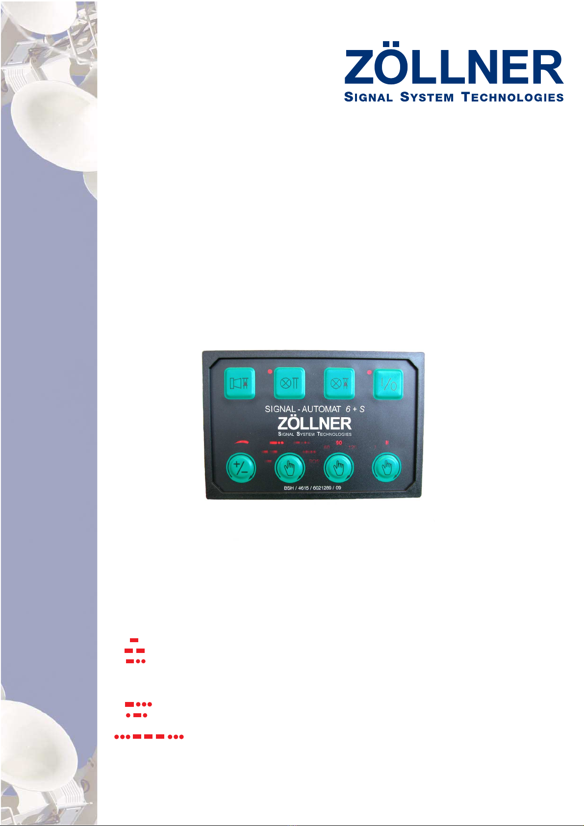
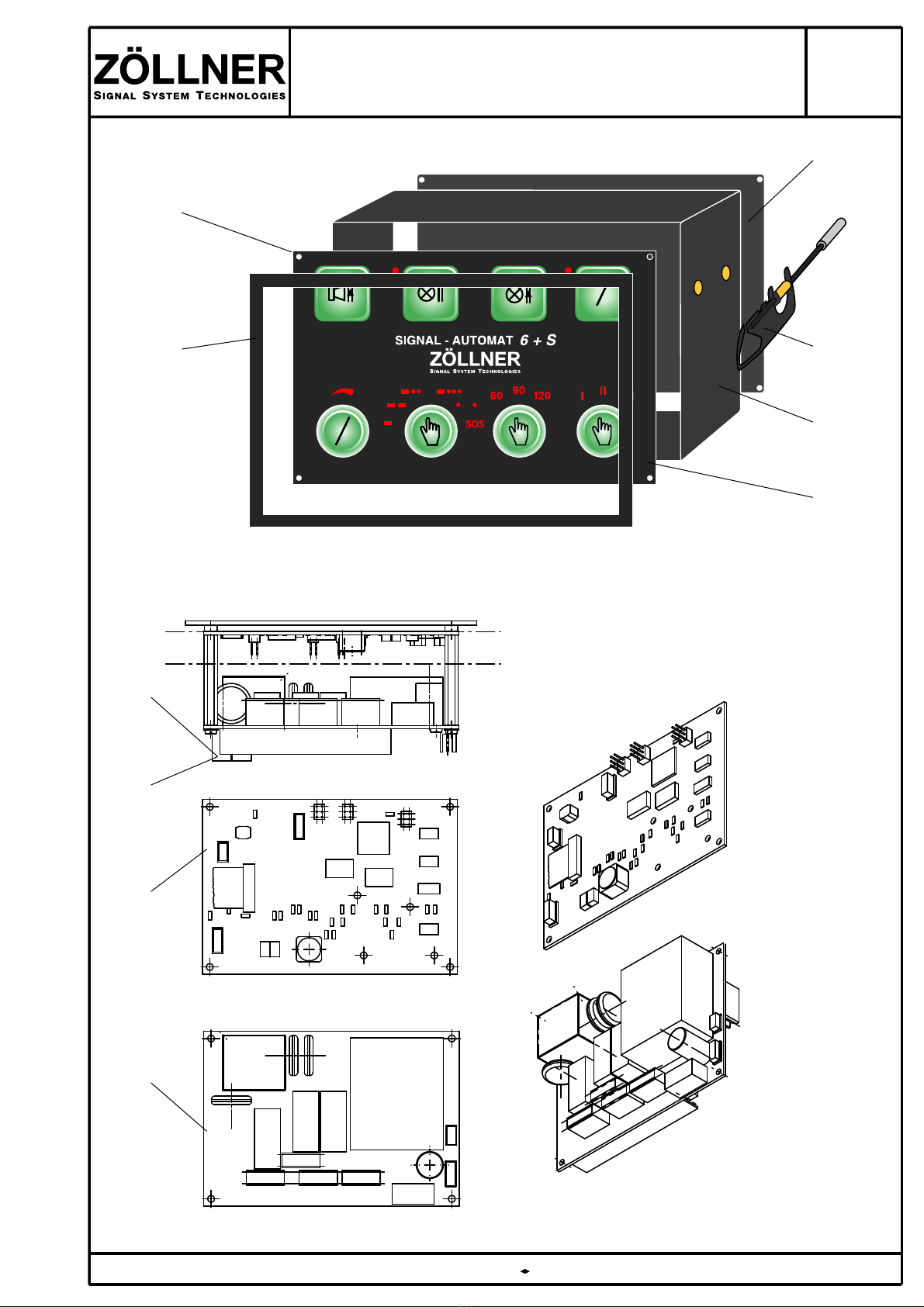
Signal Automaton 6+S
Essentials
ZÖLLNER AUTOMATON
Advantages
Characteristics of auto-
matic signals
COLREG 1972 - Rule 35 Sound Signals in
Restricted Visibility
In or near an area of restricted visibility,
whether by day or night, whistle signals shall
be used.
(a) = vessel making way through water
(b) = vessel making no way through water
(c) = vessel not under command,
vessel retricted in her ability to
maneuver, vessel engaged in fishing,
or towing or pushing another vessel
(e) = vessel towed
(g) = vessel at anchor
= SOS distress signal
- latest technical standard
- best material and workmanship - made in Germany
- functional membrane keyboard
- self-explanatory symbols
- pluggable, therefore easy installation or repair
- maintenance-free
- in the center of the bridge console
- system voltage AC 1phase or 24 V DC
- no special tools required
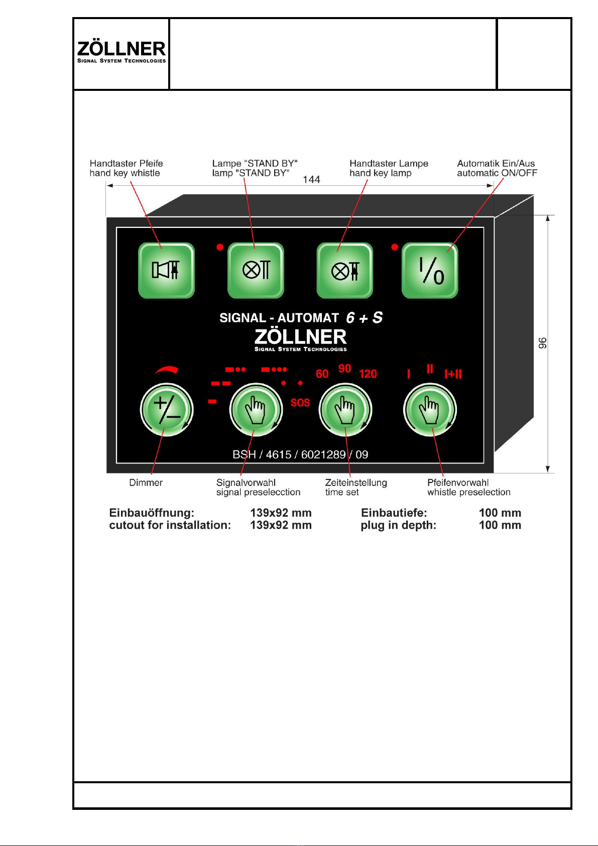
Installation
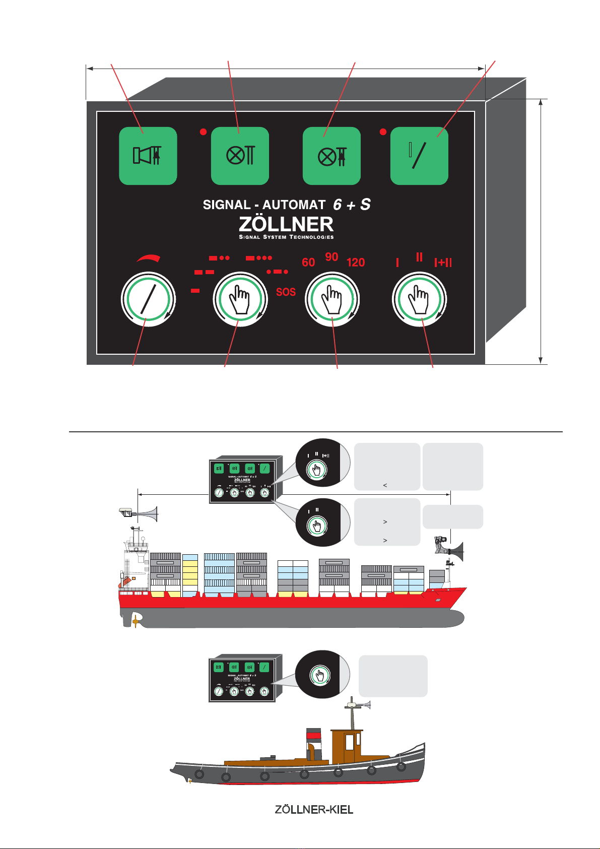
The ZÖLLNER Signal Automaton 6+S
is an automatic signal control for all
ZÖLLNER whistles with electric signal release.
It is programmed to release automatically
the maneuvring and warning signals according
to Rule 35 (a, b, c, e, g) of the Colregs 1972
and additionally the SOS distress signal.
- type approved by the BSH
- automatic and manual signal release
- sound and light signals
- ready for connection of one or two whistles,
one maneuver signal lamp and separate
push-button keys
- signal intervals adjustable
- dimmer for key illumination