Zamel Exta Life RCR-21 User manual

Zamel Sp. z o.o., ul. Zielona 27, 43-200 Pszczyna
tel.: +48 32 210 46 65, +48 32 449 15 00, fax: +48 32 210 80 04
e-mail: [email protected]
www.zamel.com
Do not dispose of this device with other waste! In order to avoid harmful effects on the
environment and human health, the used device should be stored in designated areas. For
this purpose, you can dispose of household waste free of charge and in any quantity to a
collection point set up, as well as to the shop when you buy new equipment.
Hereby, ZAMEL Sp. z o. o. declares that the radio equipment type RCR-21 is in compliance with
Directive 2014/53/EU. The full text of the EU declaration of conformity is available at the following
internet address: www.zamel.com
RADIO MOTION SENSOR
RCR-21

TECHNICAL DATA
Rated voltage: 3.0 ÷ 3.6 V (internal ½AA battery)
6 ÷ 24 V AC / DC (external voltage source)
Connection of external power source: only through PCL-21 power cradle
Maximum power consumption: 0.2 W
Transmission power: ERP<20 mW
Transmission: radio - 868.5 MHz
Battery lifetime: up to 2 years*
Transmission methods: • transmission only (with battery power supply)
• transmission / receiving (with external power supply)
Operating range: up to 300 m in open area**
Possibility to increase the range: yes - through REP-21 retransmitter
Co-operation with system elements: • with EFC-01 controller
• with selected EXTA LIFE receivers
Functionality***:
• motion detection,
• capability to work with or without twilight sensor,
• regulated sensitivity (range size of objects)
• built-in accelerometer,
• configurable NO/NC output
Measuring sensors used: digital - built-in into the sensor
Illuminance measurement range: 1 ÷ 100.000 lx
Operating range****: 1,5 ÷ 8 m
Sensor’s angle of view: 120°
Switch off delay: 10s ÷ 1h
Synchronisation time: 1 ÷ 24 h set with a 10 min. step
Operating modes:
• without twilight sensor
• night (1 + 20 lx)
• day (20 +100,000 lx)
Output: OC type - congurable (NO / NC) - through PCL-21 cradle
Motion signalling: yes - LED
Conguration of selected parameters: yes - only with external power supply (PCL-21 cradle)
Possibility of software update: yes
Housing protection rating: IP20
Installation: any - only to be operated indoors
Installation method:
• magnetic pad - installation with double-sided tape
• optionally: placing in the power cradle PCL-21 - mounted
with screws
Operating temperature range: -10 ÷ +55 °C
Dimensions: Ø 50 mm, height: 32 mm (38 mm with the magnetic pad)
Weight: 35 g
*Battery life largely depends on the number of transmissions per day and the operating temperature. The indicated lifetime
applies to default sensor settings and operation at a temperature close to room temperature.
** The operating range applies to an open area and ideal conditions without obstacles and without external interference
signals. If there are obstacles or sources of strong interference signals between the sensor and the controller, a reduction
in the range provided by the manufacturer should be provided for, which in some situations may reach even 90%. This
also applies if the sensor is mounted on a metal surface or in a metal switchgear. High power overhead and underground
power lines as well as mobile phone transmitters situated in close proximity to the devices also have a negative impact
on the operating range.
*** Some functions are only available when using the PCL-21 power cradle
**** Applies to a sensor mounted at a height of approx. 2.2 m. The range is only adjusted through the mobile application
(conguration options).
DESCRIPTION
CHARACTERISTICS
• motion detection based on a digital PIR sensor,
• built-in illuminance sensor,
• co-operation with EFC-01 controller and EXTA LIFE receivers,
• direct co-operation with selected receivers bypassing the controller,
• work with or without twilight sensor,
• regulated sensitivity (range and size of detected objects)
• anti-tamper function based on the accelerometer,
• configurable NO/NC output (connected only through a PCL-21 cradle),
• battery or external power supply (through a PCL-21 cradle),
• possibility of configuration (only with external power supply),
• possibility of software upgrade,
• quick installation using a magnetic pad,
• mobility and a convenient way of directing,
• indoor installation only.
RCR-21 sensor is designed to detect motion. Additionally, it has a built-in illuminance sensor
that controls the operation according to the intensity of sunlight. The sensor can work directly
with selected EXTA LIFE receivers or the EFC-01 controller. In the case of a controller after con-
necting the sensor with logical functions, the sensor can participate in automating of the control
processes of various devices in home installations. RCR-21 is based on a PIR digital sensor that
enables a fairly precise change of sensitivity which in turn translates into adjustment of the operat-
ing range and the size of detected objects. The sensor is equipped with an accelerometer with
anti-tamper function. Motion detection is signalled by a LED that can be switched off. The sensor
can be powered by batteries (by default) or an external voltage source (6
÷
24 V AC/DC) through
a PCL-21 power cradle. In the case of external power supply, sensor conguration is possible.
The power cradle also allows for using the sensor output, for instance to connect it to the alarm
system. The magnetic pad enables quick installation of the sensor, guarantees full mobility and
convenient directing. The sensor is to be operated indoors only (IP20).
APPEARANCE
PROG.
switch
Feeder pins
Signalling LEDs
PIR sensor
Illuminance
sensor
Magnetic pad

SENSOR POWER SUPPLY - OPTIONS
In the factory settings, RCR-21 is supplied with 3.6 V voltage from a single ½ AA battery. Alter-
natively, the device can be powered by batteries or an external voltage source 6 + 24 V AC/DC
through the PCL-21 power cradle.
NOTES:
• The sensor can be supplied with external voltage only through the PCL-21 cradle.
• When placing the sensor on the cradle, the battery does not have to be removed.
The power supply type determines the functions available to the sensor’s user:
Function Battery supply Cradle power supply
System search manually - only after the
PROG. button is pressed
automatically - search through
the application
Sending information to the
controller about motion detection /
cessation, sensor interruption (anti-
tamper function), about the current
value of illuminance
yes yes
Standard functionality from the
application level yes yes
Operating mode selection
yes - choice between the
work without twilight sensor
and night mode only
yes - work without twilight
sensor / night mode / day
mode
Co-operation with an EXTA LIFE
receiver bypassing the controller yes yes
Sensor conguration (setting of
switch-off delay, synchronisation
time, output conguration,
conguration of anti-tamper
function, sensitivity adjustment)
no yes
Software update yes yes
The power supply method is signalled in the mobile application. In the case of battery power,
the sensor informs about the battery status and provides information on the time when the last
synchronisation of the sensor with the controller occurred. The time of the last change of the sen-
sor status and the time of the tamper (alarm) occurrence is provided both in the case of external
and battery power supply.
CONNECTING POWER TO THE PCL-21 CRADLE
The PCL-21 cradle works correctly in the voltage range from 6 to 24 VAC/DC. Polarity (polarisa-
tion) of the connected voltage can be any.
PCL-21 POWER CRADLE INSTALLATION
External voltage only
through the PCL-21
cradle
Internal battery
power supply
5 mm
0,42÷0,8 mm
Due to the installation in self-
locking connectors, it is recom-
mended to use ‘solid-core’
cables with wire cross-section
of 0.14÷0.5 mm² (wire diameter
of 0.42÷0.8 mm). In the case
of stranded-core wire cables,
it may be necessary to tin
the ends.
NOTE:
• VCC voltage has to be within the limits of 6 + 24 V.
• Voltage applied to the +Vcc terminal may differ from the sensor supply voltage.
• The output (through the conguration screen) can be set as normally open NO (closed after
motion detection) or normally closed NC (opened after motion detection). The output can be
inactive.
DC power supply
or AC
transformer
230 V AC
+Vcc
OUTPUT:
6 ÷ 24 V AC/DC
Feeder
terminals
Incision
for wires
Output terminals
NO/NC
Gently pry the
contact plate with
a at screwdriver.
Take the contact
plate out of the
cradle.
Connect the
cables under
the connectors
and pull them
through the
incision.
Fix the cradle to
the bedding with
mounting screws
in the target place
of the sensor’s
operation.
Gently put the
contact plate into
the cradle, paying
attention to its
orientation with
respect to the
connector in the
cradle.
12 3 4 5

ADDING SENSOR TO THE EFC-01 CONTROLLER
1. Switch on the EFC-01 controller and log in correctly to the mobile application EXTA LIFE.
2. Go to the screen Devices » Sensors and press the button “+”. The controller will enter the sen-
sor search mode. The search process takes the maximum of 60 s. After this time, the process
needs to be resumed by pressing the “+” button again in the screen Sensors.
3.
4. Press the button ‘Stop’ and select the sensor to be paired. Next, press the button ‘Pair’.
5. After pairing, the sensor is visible on the screen “Sensors”.
If the given sensor does not appear in the list of sensors to be paired
during the search process:
- check whether the sensor is no longer paired with the controller / is
visible in the list of sensors (if so, the sensor will not be displayed
again during the pairing process),
- check whether the sensor is not marked as paired (this can happen
during an error in the removal process - consequently, the sensor is
not visible in the list of sensors but is still marked as ‘paired’) - then
reset the sensor to factory settings.
APPEARANCE OF THE SENSOR IN THE APPLICATION
The RCR-21 sensor is visible in the application right after pairing. The sensor can be named indi-
vidually and can be assigned an individual icon. It can be assigned to HOME category or to a user
NOTE: The illuminance sensor is only used for motion sensor operation depending on the
time of day or intensity of sunlight. The currently measured value of illuminance is only
displayed in the conguration screen in case of selecting night or day mode.
Items in the context menu:
• Change the name – allows for entering the sensor name.
• Change the icon – allows for assigning the icon to the sensor.
• Congure – allows for going to the sensor conguration screen (only for sensors powered by
an external voltage source).
• Assign to category – allows for assigning the sensor to a category created in the screen
HOME.
• Assign receiver – allows for assigning the sensor to the selected EXTA LIFE system receiver
(applies only to the receivers that co-operate directly with the RCR-21 sensor bypassing the
controller).
• Users – allows for assigning the sensor to a specic standard user.
• Version information – allows for displaying information about the current version of the sen-
sor’s software and its update.
• Delete – allows for removing the sensor from the system (from the EFC-01 controller).
Battery-powered sensor
When pressing the
button ‘TEST’, the
LEDs in the paired
sensor will light up
green (this allows
for identifying the
sensor)
The LEDs will blink green
and the sensor will appear
in the list of sensors to be
paired
Externally powered sensor
The LEDs blink green
and after some time
the sensor will appear
automatically in the
list of sensors to be
paired
1 1
2
Press the PROG. button
for a short time (0.5 s)
Battery-powered sensor
Externally powered sensor
information about
battery status
information on the time
when the sensor last
sent synchronisation
data to the controller
information about the
last sensor status change
an icon changing depending on the cur-
rent sensor status: no motion / motion /
battery discharged
context menu
information on the sensor’s
power supply from an external
voltage source
information about the anti-
tamper alarm if the anti-tamper
function is enabled (in addition,
the alarm occurrence is
signalled by an icon)

RCR-21 sensor configuration screen
• Switch off delay - the time after which the sensor sends receiver disa-
bling frame. The time is counted from the moment of cessation of motion
in the sensor detection area. It is set in the range from 10 s to 1 h with a
1s step.
• Synchronisation time - the time after which the sensor powered with a
battery sends mandatory status information to the controller. Based on
it, the user can check whether the sensor communicates correctly with
the controller. It is set in the range from 1 h to 24 h with a 10 min. step.
The default value is 12 h.
• Optical signalling - allows for switching on / off optical signalling when motion is detected by
the sensor. Optical signalling is enabled by default.
• Operating mode - allows for selecting 1 out of 3 operating modes:
- without light sensor - the motion sensor works all the time regardless of the value of illumi-
nance,
- night - the motion sensor works only when the illuminance level falls below the set threshold.
The activation threshold is set in the range from 1 to 20 lx (“night”),
- day - the motion sensor works only when the illuminance level is higher than the set thresh-
old. The activation threshold is set in the range from 20 to 100,000 lx (“day”),
• Measured value - illuminance value measured by the sensor. The measurement is initiated
when entering the conguration screen. The value is only displayed in the case of selecting
night or day mode.
• Output type - the parameter species whether sensor output in “no motion” status is ‘normally
open’ or ‘normally closed’. The output can be inactive. These options only apply to co-operation
with a PCL-21 power cradle.
• Anti-tamper function - enables switching on / off the accelerometer. If the accelerometer is
on, then RCR-21 is able e.g. to detect an attempt to remove the sensor from the cradle. By
default, the anti-tamper function is disabled. Sensitivity of the accelerometer is determined by
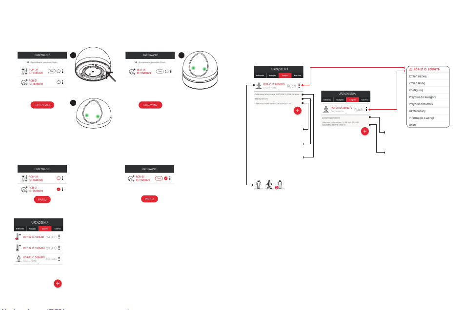
SENSOR PARAMETRISATION
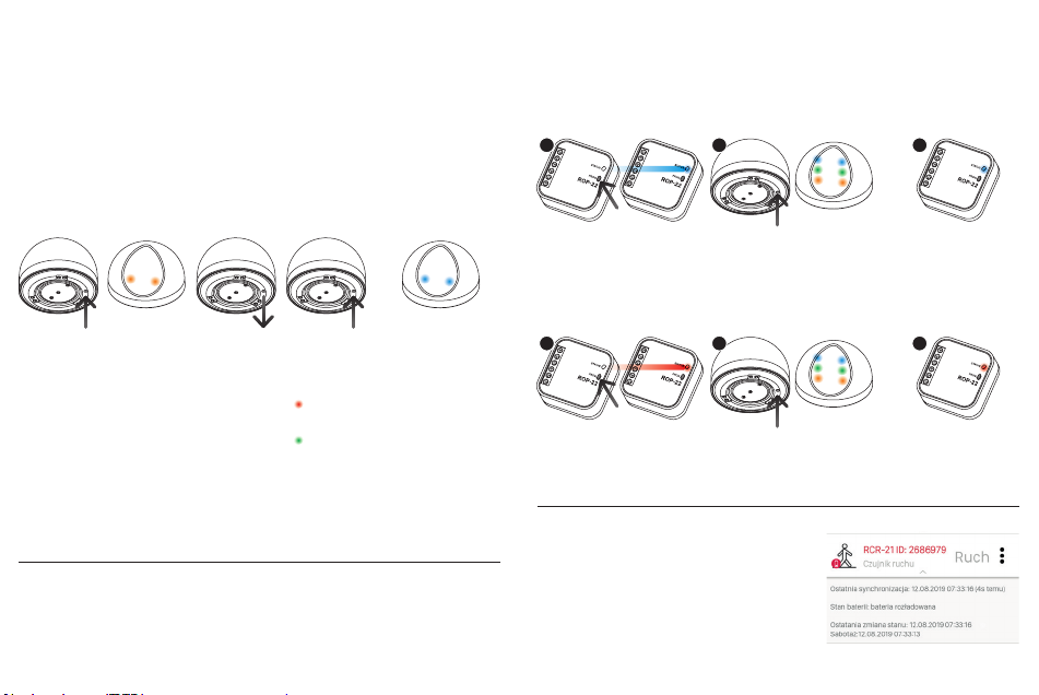
Change of conguration parameters is possible only for a sensor powered by an external voltage
source through the PCL-21 cradle. If the sensor was added to the system as a battery-powered
sensor (using the PROG. button), then in order to carry out its parametrisation, one should
If the sensor was added to the system as a sensor powered with an external
power supply, then go straight to Step 3 to parameterise it.
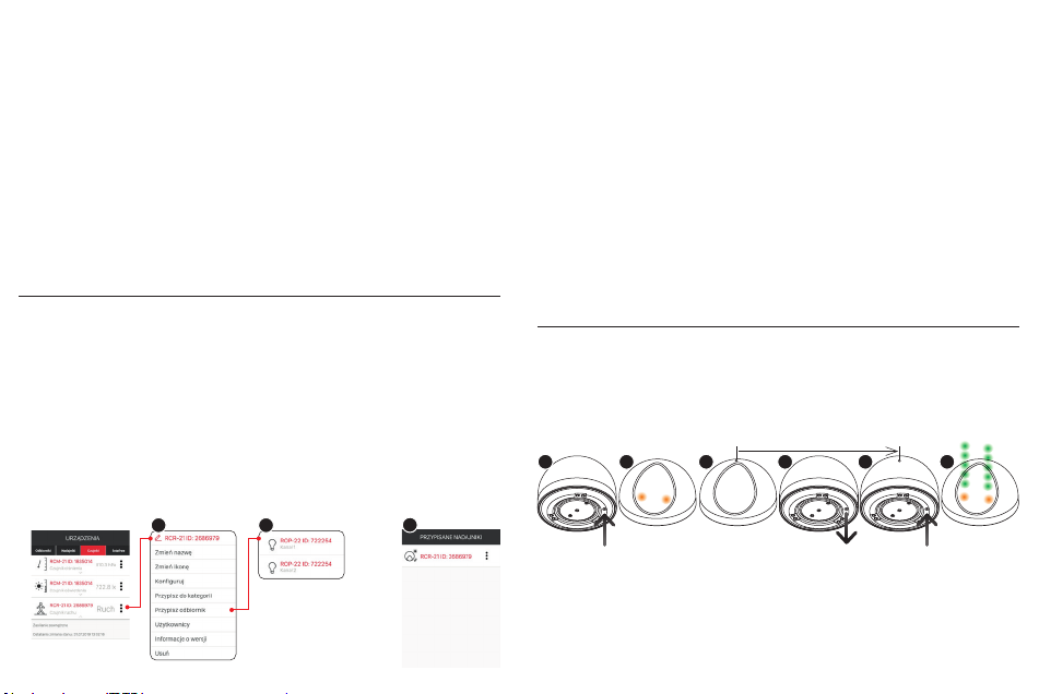
SENSOR OPERATION
Sensor operation depends on the set
operating mode.
1. MODE WITHOUT TWILIGHT
SENSOR
• The sensor detects motion all the time
regardless of the illuminance value.
When motion is detected, the activation frame (used to control the receiver directly) and the
status frame is sent owing to which the sensor status is visible in the application. At the moment
when the object stops moving or leaves the sensor’s detection area, ‘delay time’ is counted
down as set in the conguration screen (20 s by default). After counting down this time, the
sensor sends the disabling frame and the status frame again. If motion is detected again during
counting down the ‘delay time’, counting down the time stops and the sensor is waiting for the
motion to stop. When motion ceases, the time is counted down from the beginning.
• By default, motion detection is signalled by the LEDs lighting up. The signalling can be turned
off from the conguration screen.
2. NIGHT MODE
• The sensor detects motion only when the illuminance level is lower than the set threshold.
The threshold can be set within the range of 1 to 20 lx from the application using the con-
figuration screen (threshold set with a 1 lx step) or using PROG button. In the second case,
the sensor takes the value measured when selecting the night mode from the sensor menu
as the threshold value. If the measured value exceeds 20 lx, the sensor still takes 20 lx as
the threshold value. The remaining operating principle is the same as for the mode without
twilight sensor.
the parameter “Accelerometer sensitivity” set from 1 to 3 with a step of 1, where 3 means the
highest sensitivity.
• Alarm reset - the button enables resetting the alarm related to activation of anti-tamper protec-
tion.
• Sensitivity - the parameter enabled setting the detection sensitivity of the digital PIR sensor
built-in into the RCR-21 sensor. Sensitivity is set in the range from 1 to 10 with a step of 1,
where: 1- means the lowest sensitivity, 10 - means the highest sensitivity. The default value
is 5. Change of sensitivity causes a change both in sensor detection range and in the size of
detected objects. The parameter should be set experimentally depending on the sensor use.
Setting of sensitivity is based on changing parameters such as ‘threshold’, ‘detection time’ and
‘window time’. In the case of standard sensitivity change, the parameters are experimentally
selected and tabulated. In order to change these parameters manually, go to Advanced Set-
tings.
- Threshold - parameter set in the range from 0 to 255, where:
255 - high level of detection (high sensitivity) - triggering of the PIR sensor by small objects
0 - low level of detection (low sensitivity) - small objects at some distance from the PIR sensor
do not cause its trigger (default value: 222).
- Detection count - determines how many pulses need to be counted by the PIR sensor, to
send a motion information frame. To be selected from 1 to 4 pulses (default value: 3).
- Window Time - time during which the number of pulses specied by the parameter Detection
count has to occur. Set in the range from 2 to 8 s with a 2s step (default value: 6s).
In order to save the current conguration, press the button “SAVE”.
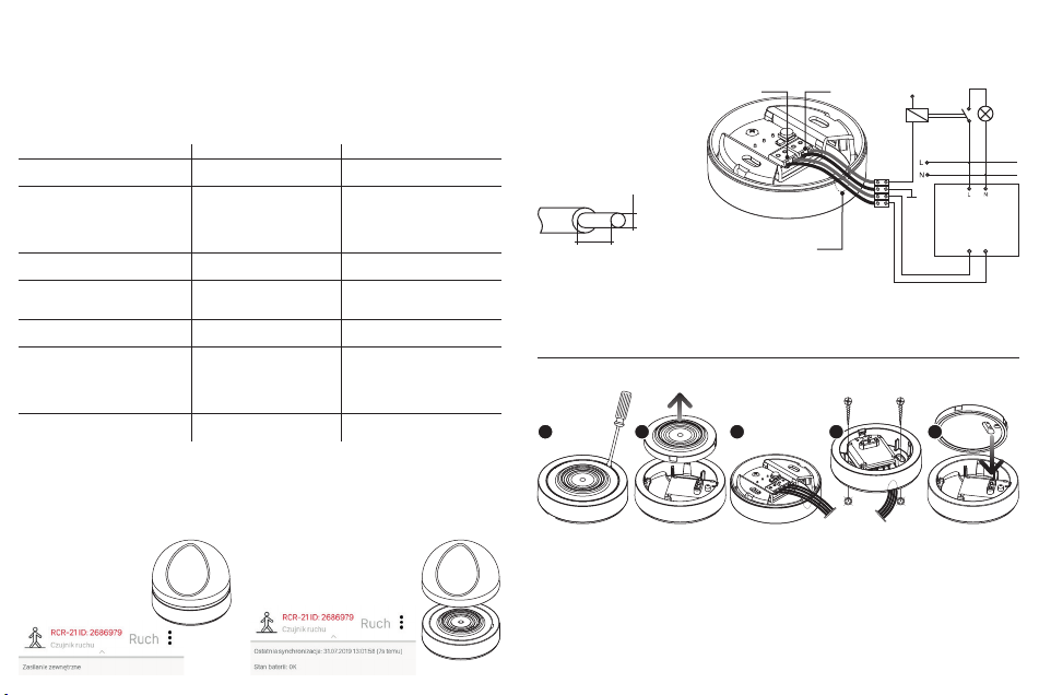
Connect 6÷24 V AC/
DC power to the
PCL-21 cradle and
place the sensor in
the cradle
Carry out
sensor pairing
again
Change the option
“Congure” for the given
measurement channel
from the level of context
menu
Set the selected
parameters and
press the button
‘Save’
2 3 4
1
1,5 m 8 m
2÷2,5 m
~120°

3. DAY MODE
• The sensor detects motion only when the illuminance level is higher than the set threshold. The
threshold can be set within the range of 20 to 100,000 lx from the application level using the
configuration screen (threshold set with a 1 lx step). The remaining operating principle is the
same as for the mode without twilight sensor.
Notes:
• Motion detection method (sensor range, and size and speed of motion of detected objects) de-
pends on the settings of the corresponding parameters in the configuration screen (‘Sensitivity’
or ‘Advances settings’).
• Each ‘Synchronisation time’ defined in the configuration, the sensor sends status information
to the controller. This is information that the sensor is working, it is visible in the system and
communicates correctly with the EFC-01 controller.
• If the RCR-21 sensor has enabled anti-tamper function, the sensor reports an alarm when the
function activates. Information about the alarm is indicated by the icon and, additionally, the
user has information when the anti-tamper function was triggered. In order to remove informa-
tion about the alarm, press the button “Reset” at ‘Alarm reset’ item in the configuration screen.
The user sets the accelerometer sensitivity, thus deciding which action is to trigger the anti-
tamper alarm (this could be, for instance, a slight interruption of the sensor or its removal from
the magnetic pad / power cradle). Sensitivity is set in the range from 1 to 3, where 1 means the
lowest sensitivity.
ASSIGNING THE RCR-21 SENSOR TO RECEIVER
FROM EXTA LIFE APPLICATION LEVEL
The RCR-21 sensor can be assigned to the selected EXTA LIFE system receiver from the ap-
plication level. After such assignment, the sensor works with the receiver directly, bypassing the
controller. Information about the currently status of the sensor is only sent to the controller. In
order to assign:
1. From the sensor menu level, select option “Assign receiver”.
2. A list will be displayed showing all receivers paired with the controller to which you can directly
assign the RCR-21 sensor.
3. Select the right receiver (or its channel) from the list) - after the selection, the assignment will
be conrmed by a message “Devices are paired”.
4. If the “Invalid data” message is displayed when attempting to assign, the given has already
been assigned to a receiver (channel).
5. Sensor assignment can be checked from the level of conguration menu of the selected re-
ceiver on the screen “Sensor assignment”. You can also delete the sensor from the receiver at
this level.
DELETING THE SENSOR FROM THE SYSTEM
When deleting the RCR-21 sensor from EXTA LIFE system, we may encounter three situations:
1. The sensor has been added to the system and operates as a battery sensor
• In order to delete it, select the option “Delete” from the context menu.
• Positive deletion will be conrmed by a message.
2. The sensor has been added to the system and operates as a sensor powered from an
external voltage source (sensor located in the cradle)
• In order to delete it, select the option “Delete” from the context menu.
• Positive deletion will be conrmed by a message.
3. The sensor has been added to the system as a sensor powered from an external voltage
source but works as a battery sensor (taken out of the cradle)
• In order to delete it, place the sensor on the power cradle.
• Select the option “Delete” from the context menu.
• Positive deletion will be conrmed by a message.
NOTE: If the sensor is not placed in the cradle, the application will show a message at the rst
attempt to delete it that the sensor needs to be placed in the cradle in order to be deleted. If the
deletion attempt is repeated after this message, then sensor will be deleted from the controller (it
will not be visible in the sensor list) but the sensor itself will not have a marker that the device has
been removed. Consequently, the sensor will not be searched again during the pairing process. It
is then necessary to reset the sensor to its factory settings.
RESET OF THE SENSOR TO FACTORY SETTINGS
Reset to factory settings restores the default values of conguration parameters and resets the
marker informing about the sensor’s pairing with the EXTA LIFE system controller.
NOTE: In order to search the sensor again in the pairing process (which applies to power supply
from an external voltage source), the marker informing about pairing has to be removed (reset)
and the sensor cannot be found in the screen Devices » Sensors (it must be removed from the
system / EFC-01 controller).
2
15
<5s
(0,5s)
Press the
PROG button
for more
than 5s
When the LED goes out, release the PROG
button and press it again for a short time
(0.5s) in less than 5s after the LED goes out
The LEDs will
quickly blink
orange, then
they will blink 5
times green and
the sensor will
move to normal
operation
The LEDs will
light up orange
and go out after
1s - keep PROG
button pressed.
(5s)
13 4 5 62

OPERATING MODE SELECTION
Using the PROG button, the user can choose one of two modes of operation:
1. Work without light sensor (the motion sensor works all the time).
2. Work with light sensor (the sensor works only when the illuminance is lower than the set thresh-
old). The trigger threshold is set in the range from 0 to 20 lx based on the current measurement
when choosing the mode with light sensor. If the currently measured level is > 20 lx, the refer-
ence value is the limit value, i.e. 20 lx.
DIRECT CO-OPERATION OF RCR-21 SENSOR
WITH SELECTED EXTA LIFE RECEIVERS
The RCR-21 sensor can operate directly with selected EXTA LIFE receivers bypassing the EFC-
01 controller. This co-operation only applies to such receivers as: ROP-21, ROP-22, ROM-22,
ROM-24. In the case of other receivers, use an EFC-01 controller and a logical function module.
NOTE: Do not cover the aperture if the mode with light sensor is selected so as not to
distort the result of illuminance measurement.
In order to programme a new threshold value, enter the operating mode programming
procedure again and select the mode with light sensor again.
OPERATING MODE SELECTION:
1. Press the PROG button for > than 1s. After pressing the button, the LEDs light up orange.
2. When the LEDs go out, release the button PROG.
3. Next, by pressing the button PROG for a short time (0.5 s), select the proper operating mode:
- the LEDs lit up red - work without light sensor,
- the LEDs lit up green - work with the light sensor.
4. After approx. 3s, the sensor will quickly blink blue and the user will exit the mode programming
procedure.
Example: Programming of RCR-21 to the rst channel ROP-22
Example: RCR-21 programming for the second ROP-22 channel
SENSOR PAIRING WITH SELECTED EXTA LIFE RECEIVERS
1. Press the PROG. button for a short time (0.5s) on the receiver..
2. When the receiver enters the programming procedure of the given channel, press for a short
time (0.5 s) the PROG button in the RCR-21* sensor.
3. After pressing the PROG button, the LEDs in the sensor light up orange and then blink green,
which signals the sending of programming frames. The stage of assigning the sensor to the
receiver ends with the LEDs lighting up blue.
DISCHARGED BATTERY SIGNALLING
Battery discharge status is only signalled in the mobile
application by the icon and appropriate message dis-
played under the sensor’s name. If the sensor works
with an external supply (is placed in the PCL-21 power
cradle), information about discharged battery is not
displayed.
The need to replace the battery is signalled when its
voltage decreases to <2.1 V.
(>1s)
When the LEDs
go out, release
the button
PROG
By pressing the
button PROG for a
short time, select
the proper operat-
ing mode:
LEDs light is
red - work without
light sensor.
LEDs light is
green - work with
the light sensor.
After 3s of selection
of the operating
mode, the LEDs will
blink blue - exit from
the programming
procedure. If the mode
with light sensor is
selected, the sensor
measures the illumi-
nance during this time.
This value is taken as
the threshold value.
Press the PROG
button more
than 1s
The LEDs will
light up orange
and go out
after 1s
Press the PROG. button for a
short time (0.5s) on the receiver.
Wait a moment until the LED
STATUS lights up blue
Press the PROG. button for a
short time (0.5s) on the receiver.
Wait approx. 5s until the
STATUS LED lights up red
(programming of channel 2).
Press the PROG. button for a short time
(0.5s) on the RCR-21 as quick as pos-
sible. The LEDs in the sensor will blink
orange, green and nally blue
Press the PROG. button for a
short time (0.5s) on the RCR-21 as
quick as possible. The LEDs in the
sensor will blink orange, green and
nally blue
The STATUS LED will
blink and go out. This
means that the sensor is
correctly assigned to the
1st channel of the receiver
The STATUS LED will
blink and go out. This
means that the sensor is
correctly assigned to the
1st channel of the receiver
(0,5s)
(0,5s)
1
1
3
3
2
2

BATTERY REPLACEMENT
Unscrew the base
using the magnetic
pad
Gently remove
the base from
the body
Move the battery
from the box
using a at
screwdriver.
Insert a new bat-
tery to the box,
please mind the
polarity
Put the cradle
into the body and
close it with the
magnetic pad
12 543
Case 1 - Sensor placed on PCL-21 cradle (powered externally)
From the context menu, go to the screen ‘Version information’. The update starts after pressing
the button ‘Update’. During the update, the sensor and the controller are switched to service fre-
quency and control is not possible. Successful completion of the update is indicated by a message
“Device successfully updated”.
If the sensor update fails for some reason, it is marked as a sensor with an update error from the
controller side. The sensor loses its functionality (as indicated by steady blinking of the green LED
STATUS). However, it can be recovered again by repeating the upgrade process.
NOTE: in case of error during the upgrade, do not remove the sensor from the system or
reset it to factory settings. It may cause a full loss of functionality and necessity to return
the product to the service.
NOTE: Update does not work through the REP-21 retransmitter. If the signal from the sensor
passes through the retransmitter, in order to update move the sensor closer to the controller (or
possibly temporarily remove the retransmitter from the system and again add it after the update
is completed).
12 3
SOFTWARE UPDATE
Update requirements:
• the update can only be performed by a user with Root or Administrator rights,
• update is available for the sensor powered by the PCL-21 cradle (recommended methods) and
for a battery powered sensor (obligatory method).
If a new version of the software appears, the application will signal the need to update the sen-
sor. Updates can also be checked on the screen ‘Version information’. If the button “Update” is
highlighted, a newer software version is available.
Case 2 – Battery-powered sensor
After placing the battery in the sensor, the update process begins. Its course is exactly the same
as when powered from an external voltage source. It is possible to retry the update process in
case of an error.
In the application,
go to the screen
‘Version informa-
tion’.
Take the battery
out of the sensor
(see chapter
‘Battery replace-
ment’)
Press
the button
‘Update’
Place the battery in the
sensor in a time shorter
than 5s after pressing
the button ‘Update’
<5s
12 3 4
ATTENTION!
DANGER OF EXPLOSION IF THE BATTERY IS REPLACED WITH A BATTERY OF WRONG
TYPE! DISPOSE OF WORN OUT BATTERIES AS STATED IN THE INSTRUCTIONS.

WORK WITH REP-21 RETRANSMITTER
The sensor can work with a REP-21 retransmitter. This co-operation is required if problems are
found in radio communication between the sensor and the controller. It is then recommended to
install the REP-21 retransmitter between these devices. Co-operation between the sensor and the
retransmitter can be implemented in two ways::
I. Sensor entered directly into the retransmitter (bypassing the controller)
In order to enter the sensor directly into the REP-21 retransmitter:
1. Press the button PROG. for a short time (0.5s) on the REP-21 retransmitter.
2. When the LED in the retransmitter lights up blue, in less than about 3 s press for a short time
(0.5s) the PROG. button in the sensor. The sensor will send data to the retransmitter.
3. The programming procedure ends with the LED going out in the retransmitter.
After such assignment, the status frame (informing about the sensor status in the application) is
retransmitted along with control frames for the selected EXTA LIFE receiver (it is important in case
of direct co-operation between the sensor and the receiver).
II. Sensor and retransmitter added to the EFC-01 controller
When the sensor and retransmitter are added to the controller, one can deal with two cases::
1 The retransmitter and sensor are paired with the EFC-01 controller
In this case, only status frames are retransmitted automatically. It is required to pair the retrans-
mitter with the EFC-01 controller. The sensor has to be added to the system using the PCL-21
power cradle.
In a case when the sensor was typically added as a battery sensor (using the button PROG.), it is
necessary to put it on the power cradle and pair it again (exactly as in the case of Conguration).
After pairing, the sensor can be removed from the cradle and it can still work as a battery sensor.
2 Sensor added to the retransmitter through the option “Assign sensor”
This solution should be used when:
- the sensor operates with battery power and we do not have a PCL-21 power cradle,
- the sensor works directly with the selected EXTA LIFE receiver.
Select the option “Assign sensor” from the retransmitter menu, and then select the sensor to be
entered into the retransmitter. After such assignment, the status frame (informing about the sensor
status in the application) is retransmitted along with control frames for the selected EXTA LIFE
receiver (in case of direct co-operation between the sensor and the receiver).
Table of contents
Other Zamel Accessories manuals

Zamel
Zamel Sundi Compact User manual

Zamel
Zamel DUO GNS-943 User manual

Zamel
Zamel CKM - 01 User manual

Zamel
Zamel RCR-01 User manual

Zamel
Zamel MCR-08 User manual

Zamel
Zamel Sundi GLASSO User manual

Zamel
Zamel SUNDI BIM-BAM GNS-921/N User manual

Zamel
Zamel exta MCR-01 User manual

Zamel
Zamel MCR-09 User manual

Zamel
Zamel sundi SONATA ST-916 User manual

Zamel
Zamel ST-940 User manual

Zamel
Zamel SRP-02 User manual

Zamel
Zamel sundi ST-330 User manual

Zamel
Zamel Exta CAH-01 User manual

Zamel
Zamel Sundi DNT-911/N User manual

Zamel
Zamel sundi LOOPO ST-366 User manual

Zamel
Zamel BIM-BAM GNS-921 User manual

Zamel
Zamel Sundi Twist User manual

Zamel
Zamel DISCO User manual

Zamel
Zamel SUNDI BIM-BAM GNT-921/N-SZR User manual