manuals.online logo
Brands
  1. Home
  2. •
  3. Brands
  4. •
  5. Zamel
  6. •
  7. Accessories
  8. •
  9. Zamel MCR-08 User manual

Zamel MCR-08 User manual

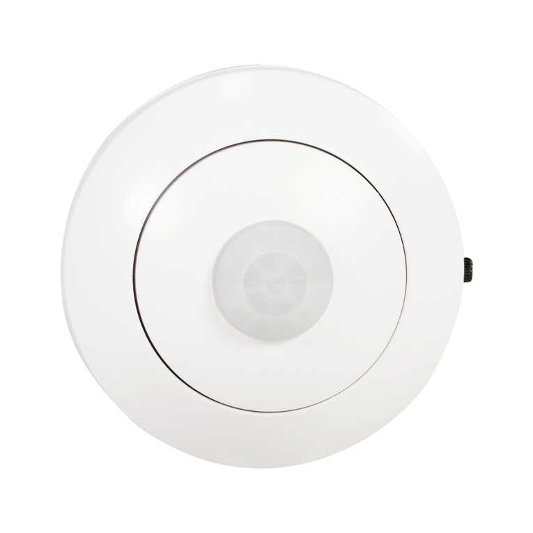
MOTION SENSOR PIR 120/360° miniature
with a probe, IP65 on the MCR-08 conductor USER MANUAL
ZAMEL Sp. z o.o.
ul. Zielona 27, 43-200 Pszczyna, Poland
Tel. +48 (32) 210 46 65, Fax +48 (32) 210 80 04
www.zamel.com, e-mail: [email protected]
plik: mcr-08_inst_ext_gb | modykacja: 14.05.2020
APPEARANCE
FEATURES
DESCRIPTION
NOTE
• Detection angle 360 / 120 degrees
• Selectable detection area: 3 m / 6 m
• Light on time setting: 5s, 30s, 1 min., 3 min.,
5 min., 8 min.
• Adjustment of the in-built light sensor 10 lux /
2000 lux
• Miniature design of the device facilitates its
installation in different places
• Hermetic probe on the cable can be used to
adapt the device to different applications.
The MCR-08 miniature motion sensor is
designed for automatic light control or for con-
trolling any other electric receiver. Its design is
based on a state of the art infrared (PIR) motion
detector system. The device detects motion in
the monitored area within the radius of ca. 3 or
6 m, within 120° / 360° around the sensor. The
device was designed to miniaturize the detec-
tor’s electronic part and to enable its operation
with the use of an external, hermetic sensor
(IP54) mounted on a cable. The condition of
external light intensity is additionally veried. If
the device detects motion and the light intensity
level is below the setting value, the sensor will
turn the light on and start to count the preset
time, after which the light will be automatically
turned off. The device includes a set of switches
for simple and repeatable setting and adjust-
ment. This facilitates the installation of devices
in the case of larger systems. Thanks to its spe-
cic design and operation, the sensor provides
optimal control over the energy ow, optimizing
the costs of illuminating communication routes,
stairs, toilets and facilities, etc. The design of
the device’s mechanics facilitates the installa-
tion of the sensor directly in a suspended ceil-
ing and in drywall. It is also possible to adapt
the device to t in a junction box, where the
cable probe will monitor the preset area after it
is led out and xed in a desired place under the
equipment cover.
Read this User Manual carefully before connecting and operating the device. The device must be installed by a qualied electrician. Connect this product
to a single-phase power system according to applicable standards. See this Manual for the wiring instructions. The activities related to the installation, con-
nection and adjustment should be performed by qualied electricians, familiar with the User Manual and functions of the device. Do not open or otherwise
disassemble the product enclosure; otherwise the product warranty will be void and an electrocution hazard may occur. Prior to installing and wiring this
product, make sure that the wiring to be connected is not live. The conditions and methods of transport, storage and operation of this product may affect its
performance. Do not install the products if any of its components are missing, the product is damaged or deformed in any way. If any malfunctions are found,
consult the manufacturer. The manufacturer is not be liable for any damage resulting from improper installation or operation of the device. Any repairs or
modications made independently will void the warranty. Since the technical data are subject to constant modications, the Manufacturer reserves the right
to change the product characteristics and introduce other design solutions for the device.
TECHNICAL DATA
Power supply voltage: 230 V AC
Voltage frequency: 50 Hz
Motion detection angle: 120 / 360 degrees
Maximum effective zone: 3 lub 6 m (selectable)
Time to turn on the lighting: 5s, 30s, 1 min, 3 min, 5 min, 8 min
Time measurement accuracy: ± 15 % of the selected value
Scope of light sensor settings: 10 ÷ 2000 lux
Acceptable load:
Traditional bulbs: 800 W
Fluorescent tubes: 200 W
LEDs: 15 W
Power consumption: <0,5W
Installation height: 2 ÷ 4 m
Operating temperature: -20 ÷ + 40 °C
Permissible humidity: < 93% RH
Dimensions: 55,5 x 55,5 mm
Weight: 0,4 kg
Do not dispose of this device in
the trash can with other waste!
In order to avoid harmful effects
on the environment and human
health, store used device in
specially designated places.
Household electronic waste
can be returned for free and in any amount
to the collection point established for this
purpose, and also to the shop when buying
new equipment.
Motion sensor
Switching devices
Connection
cables
NOTES
INSTALLATION & CONNECTION RELAY CAPACITY
1. Select the device installation site.
2. Disconnect the power supply circuit with a fuse, circuit break-
er or switch disconnector connected to an appropriate circuit.
3. Check the de-energized condition on the power supply ca-
bles by means of the appropriate instrument.
4. Install the device in its ultimate position. Use the installation
holes on the sides of the device for fixing it.
5. Adjust the device using the following switches:
P1: Light intensity, at which motion will be detected. When
the switch is moved to its upper position, the device will
be started at night. When the switch is moved down - the
device will operate continuously, regardless of the light
intensity.
P2: Sensor effective range selection The sensor can detect
within the range of ca. 3 m (lower position) or ca. 6 m
(upper position).
P3-P8:Light up time selection. The time, in which light will
go on is selected by moving the respective switch, e.g.
move the switch to the symbol “5” to set a 5-second light
up time.
6. Connect the cables in line with the connection diagram.
7. Connect the sensor included in the set.
8. Specify the supply voltage. The device automatically adapts
to the operating conditions. The device will be ready to work
after about 30-40 seconds.
• Since the device analyzes changes in
infrared radiation caused by thermal
changes occurring in the monitored area
to detect motion, it should not be installed:
- opposite light-reflecting surfaces, such
as mirrors,
- in the vicinity of heat sources, such as
radiators, fireplaces, air conditioners,
high-power lamps, etc.,
- in the vicinity of objects which can be
moved by gusts of wind, such as cur-
tains, tall plants, bushes, etc.
• The device should be installed at ca. 2÷4
m from the ground. Then, the monitored
area will be ca. 3 or 6 m in diameter.
800 W
400 W
200 W
300 W
15 W
WARRANTY CARD
24-month commercial warranty
granted by the manufacturer
Seller’s stamp and signature with date of sale
1. ZAMEL Sp. z o.o. grants a 24-month warranty for the goods it sells.
2. The warranty granted by ZAMEL Sp. z o.o. does not cover:
a)mechanical damage caused by transport, loading/unloading or other circumstances,
b) any damage resulting from improper installation or use of the goods sold by ZAMEL Sp. z o.o.,
c) any damage resulting from any modications made by the BUYER or any third party to the sold goods or to the equipment
required for the proper functioning of the sold goods,
d) damage caused by any force majeure event or another fortuitous event beyond any reasonable control of ZAMEL Sp. z o.o.
3. The BUYER shall report all warranty claims in writing at the point of sale or to ZAMEL Sp. z o.o.
4. ZAMEL Sp. z o.o. will examine each warranty claim as regulated by the applicable provisions of the Polish law.
5. The form of warranty claim resolution, i.e. replacement, repair or refund of the price of purchase, shall be decided upon by
ZAMEL Sp. z o.o.
6. This warranty does not exclude, limit or suspend any rights of the BUYER arising from the statutory or regulatory laws con-
cerning implied warranty for defects of sold goods.
6 m
3 m
360°
2,2 ÷ 4 m
6 m
3 m
red
230 V AC 50/60 Hz
Operating range:
3 m / 6 m
Activation time:
5 s, 30 s, 1 min.,
3 min., 5 min.,
8 min.
Illumination level:
nigh / continuous
brown
blue
5˝ 30˝ 1΄
1 2 3 4 5 6 7 8
3΄ 5΄ 8΄
ON

Other Zamel Accessories manuals

Zamel BIM-BAM GNT-921 User manual

Zamel

Zamel BIM-BAM GNT-921 User manual

Zamel ynsta PDK-250/2 User manual

Zamel

Zamel ynsta PDK-250/2 User manual

Zamel SUNDI BIM-BAM GNS-921/N User manual

Zamel

Zamel SUNDI BIM-BAM GNS-921/N User manual

Zamel sundi BULIK User manual

Zamel

Zamel sundi BULIK User manual

Zamel sundi SUITA User manual

Zamel

Zamel sundi SUITA User manual

Zamel ST-930 User manual

Zamel

Zamel ST-930 User manual

Zamel sundi ST-260 User manual

Zamel

Zamel sundi ST-260 User manual

Zamel sundi SONATA ST-916 User manual

Zamel

Zamel sundi SONATA ST-916 User manual

Zamel sundi CALIPSO ST-980 User manual

Zamel

Zamel sundi CALIPSO ST-980 User manual

Zamel SUNDI FORTE GNT-223-BIA User manual

Zamel

Zamel SUNDI FORTE GNT-223-BIA User manual

Zamel sundi LOOPO ST-366 User manual

Zamel

Zamel sundi LOOPO ST-366 User manual

Zamel exta MCR-01 User manual

Zamel

Zamel exta MCR-01 User manual

Zamel Sundi Largo User manual

Zamel

Zamel Sundi Largo User manual

Zamel sundi BULIK User manual

Zamel

Zamel sundi BULIK User manual

Zamel sundi BUZZER DNT-255 User manual

Zamel

Zamel sundi BUZZER DNT-255 User manual

Zamel sundi MULINO DNS-222 User manual

Zamel

Zamel sundi MULINO DNS-222 User manual

Zamel SUNDI TURBO GNT-931-BEZ User manual

Zamel

Zamel SUNDI TURBO GNT-931-BEZ User manual

Zamel Sundi Traditional User manual

Zamel

Zamel Sundi Traditional User manual

Zamel LARGO GNS-208 User manual

Zamel

Zamel LARGO GNS-208 User manual

Zamel SUNDI VIVO GNT-224 User manual

Zamel

Zamel SUNDI VIVO GNT-224 User manual

Zamel ST-925 User manual

Zamel

Zamel ST-925 User manual

Zamel SUNDI BIM-BAM GNT-921/N-SZR User manual

Zamel

Zamel SUNDI BIM-BAM GNT-921/N-SZR User manual

Zamel Sundi OVAL ST-990 User manual

Zamel

Zamel Sundi OVAL ST-990 User manual

Zamel BIM-BAM GNS-921 User manual

Zamel

Zamel BIM-BAM GNS-921 User manual

Popular Accessories manuals by other brands

HBM PW29 Series Mounting instructions

HBM

HBM PW29 Series Mounting instructions

First Alert SFA200 user manual

First Alert

First Alert SFA200 user manual

TP active fun TP470 Instructions for assembly, maintenance and safe use

TP

TP active fun TP470 Instructions for assembly, maintenance and safe use

Silvercrest SRL 100 A1 operating manual

Silvercrest

Silvercrest SRL 100 A1 operating manual

B-Link Video Doorbell Setup guide

B-Link

B-Link Video Doorbell Setup guide

Easy@Home GT-HUB-02-UK user manual

Easy@Home

Easy@Home GT-HUB-02-UK user manual

Distech Controls UNIWAVE user guide

Distech Controls

Distech Controls UNIWAVE user guide

SICK TiM8 DistanceGuard Series operating instructions

SICK

SICK TiM8 DistanceGuard Series operating instructions

IV Produkt Envistar Top Assembly instructions

IV Produkt

IV Produkt Envistar Top Assembly instructions

MTS Sensors Temposonics T Series Operation manual

MTS Sensors

MTS Sensors Temposonics T Series Operation manual

SKY-WATCHER EQ1 Instrucution manual

SKY-WATCHER

SKY-WATCHER EQ1 Instrucution manual

Alula RE101 quick guide

Alula

Alula RE101 quick guide

SCI WLS555 Installation and operation manual

SCI

SCI WLS555 Installation and operation manual

Toa D-001T Specifications

Toa

Toa D-001T Specifications

iHome Health POWERUVC II iUV3 installation guide

iHome

iHome Health POWERUVC II iUV3 installation guide

Detcon TP-700 instruction manual

Detcon

Detcon TP-700 instruction manual

HSS Hire 56781 Operating & safety guide

HSS Hire

HSS Hire 56781 Operating & safety guide

Azbil AUD100 Series user manual

Azbil

Azbil AUD100 Series user manual

manuals.online logo
manuals.online logoBrands
  • About & Mission
  • Contact us
  • Privacy Policy
  • Terms and Conditions

Copyright 2025 Manuals.Online. All Rights Reserved.