manuals.online logo
Brands
  1. Home
  2. •
  3. Brands
  4. •
  5. Zamel
  6. •
  7. Accessories
  8. •
  9. Zamel CKM - 01 User manual

Zamel CKM - 01 User manual

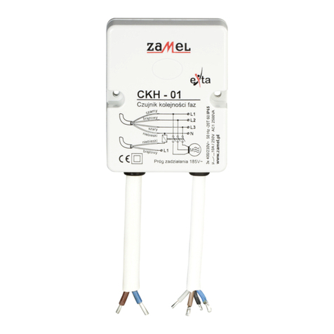
PHASE SEQUENCE SENSOR CKM - 01 INSTRUCTION MANUAL
ZAMEL Sp. z o.o.
ul. Zielona 27, 43-200 Pszczyna, Poland
tel. +48 (32) 210 46 65, fax +48 (32) 210 80 04
www.zamel.com, e-mail: [email protected]
plik: inst_ext_gb_ckm-01 | modykacja: 19.10.2015
FEATURES
DESCRIPTION
APPEARANCE
● Wrong phase sequence protection,
● phase fading protection,
● voltage asymmetry protection,
● (asymmetry) switch on threshold regu-
lation,
● switch off delay and voltage hysteresis
● resistant to momentary voltage drops,
● momentary voltage fading protection
max 10 A capacity,
● monomodular casing,
● TH-35 DIN rail installation.
The CKM-01 phase sequence sensor
device is used to protect devices powe-
red from a three-phase installation (e.g.
a motor) from being damage in case of
phase voltage switch off. It is because of
phase voltage asymmetry or wrong phase
sequence. The threshold switch on value
is can be adjusted by the user by means
of a potentiometer. The system does not
protect from symmetrical voltage drop and
it is powered from L1 phase. The switch
off delay and voltage hysteresis cause the
system is resistant to momentary voltage
changes.
The device is designed
for three-phase installa-
tion and must be instal-
led in accordance with
standards valid in a par-
ticular country. The devi-
ce should be connected
according to the details included in this
operating manual. Installation, connec-
tion and control should be carried out
by a qualied electrician staff, who act in
accordance with the service manual and
the device functions. Disassembling of
the device is equal with a loss of guaran-
tee and can cause electric shock. Before
installation make sure the connection ca-
bles are not under voltage. The cruciform
head screwdriver 3,5 mm should be used
to instal the device. Improper transport,
storage, and use of the device inuence
its wrong functioning. It is not advisable
to instal the device in the following cases:
if any device part is missing or the device
is damaged or deformed. In case of im-
proper functioning of the device contact
the producer.
CAUTION
TECHNICAL PARAMETERS
CKM-01
Supply cables: L1, N
Input rated voltage / supervised: 230/400 V~
Rated current: -15 ÷ +10 %
Rated frequency: 50 / 60 Hz
Znamionowy pobór prądu: 34 mA
Measure terminals: L1, L2, L3
Correct phase sequence indicator: LED green
Wrong phase sequence indicator: LED red
Voltage threshold adjustment: 170 V ÷ 200 V
Voltage hysteresis: approx. 10 V
Switch on delay t1: 5 sec -10 sec
Switch off delay t2: 1 sec - 5 sec
Output relay parameters: 1NO/NC - 10 A / 250 V AC1 2500 VA
Number of terminal clamps: 7
Section of connecting cables: 0,2 ÷ 2,50 mm2
Ambient temperature range: -20 ÷ +60 oC
Operating position: free
Mounting: TH35 rail (acc PN-EN 60715)
Protection degree: IP20 (PN-EN 60529)
Protection class: II
Overvoltage category: II
Pollution degree: 2
Rated impulse withstand voltage: 2 kV (PN-EN 61000-4-5)
Dimensions: monomodular (17,5 mm) 90x17,5x66 mm
Weight: 77 g
Reference standards: PN-EN 60730-1; PN-EN 60730-2-1
PN-EN 61000-4-2,3,4,5,6,11
Relay output terminals (11, 12, 14)
Power supply terminal (N)
Power supply terminal/measure (L1)
Correct phase sequence
Voltage threshold
adjustment
Wrong phase
sequence indicator
indicator
Measure terminal (L3)
Measure terminal (L2)
TIME COURSE
CONNECTING
MOUNTING, FUNCTIONING
EXAMPLE OF INSTALLATION
WARNING!
The relay system is powered from
L1 phase. The relay switch off time delay
depends on output power connected to a
three–phase installation. The lack of two
phases causes the sensor to switch on.
INNER DIAGRAM
SIGNALLING
DIMENSIONS
PRODUCT FAMILY
CKM-01 phase sequence sensor belongs to
CKX asymmetry sensor family.
1. Disconnect the power supply from the
mains by the phase fuse, the circuit-bre-
aker or the switch-disconnector that are
joined to the proper circuit,
2. Check if there is no voltage on connec-
tion cables by means of a special me-
asure equipment,
3. Install CKM-01 device in the switchbo-
ard on TH-35 DIN rail,
4. Connect the cables with the terminals
according to installing diagram,
5. Switch on the power supply from the
mains,
6. Adjust voltage threshold that switches
on phase sequence sensor.
After power supply has been applied
(from L1 phase) the sensor controls the cor-
rect phase order. In case there is a wrong
phase sequence, the LED red switches on
marked „” (outputs 11–12 are closed, the
motor is switched off, the alarm is switched
on). The LED green switches on in case
of a correct phase sequence „ ” (outputs
11–14 are closed, the motor is switched on)
and the sensor controls voltage values in
particular phase. The relay remains in on po-
sition and the controlled load (e.g. motor) is
switched on till the voltage value is correct in
every phase. In case there is a lack of any of
the phases or there is a voltage drop below
the adjusted asymmetry threshold the relay
is switched off. There is a short time delay in
switching off the relay (t2 from 1 to 5 sec).
The device is resistant to momentary volta-
ge drops. Another motor switch on follows
(outputs 11–14 are closed) when the voltage
is 10V higher from the adjusted voltage thre-
shold (voltage hysteresis), and after t1 time
(from 5sec to 10sec) is over. LED diodes
are switched on till every phase voltage is
below 50 V.
:RobertRoszkowski
e-mail:senseir@wp.pl
PROTECTED
DEVICE
SIGNALLING
О
ОVOLTAGE ASYMMETRY
☼
О
CORRECT PHASE SEQUENCE
INDICATOR
О
☼
WRONG PHASE SEQUENCE
INDICATOR
The phase sequence sensor protects the motor does not work in case of supply
failure. The sensor enables the motor to work only when there is a correct phase
sequences.
GUARANTEE CARD
There is 24 months guarantee on the product
Salesman stamp and signature, date of sale
1. ZAMEL Ltd. assures 24 months guarantee for the product.
2. The manufacturer’s guarantee does not cover any of the following actions:
a) mechanical damage during transport, loading / unloading or under other circumstances
b) damage caused by incorrect mounting or misuse of ZAMEL Ltd. products
c) damage caused by unauthorised modications made by the PURCHASER or any third parties to the product or any other
devices needed for the proper product functioning,
d) damage caused by Act of God or any other incidents independent of the manufacturer
3. The PURCHASER shall lay any claims on grounds of the guarantee card in writing to the dealer or to ZAMEL Ltd.
4. ZAMEL Ltd. is liable for processing any claim according to current Polish legislation
5. ZAMEL Ltd. shall process the claim at its own discretion: product repair, replacement or money return
6. The manufacturer’s guarantee is valid in the Republic of Poland.
7. The Purchaser’s statutory rights in any applicable legislation whether against the retailer arising from the purchase contract
or otherwise are not affected by this guarantee card.

Other Zamel Accessories manuals

Zamel sundi BUZZER DNT-255 User manual

Zamel

Zamel sundi BUZZER DNT-255 User manual

Zamel RCR-01 User manual

Zamel

Zamel RCR-01 User manual

Zamel MCR-07 User manual

Zamel

Zamel MCR-07 User manual

Zamel Exta SOS-01 User manual

Zamel

Zamel Exta SOS-01 User manual

Zamel sundi CALIPSO ST-980 User manual

Zamel

Zamel sundi CALIPSO ST-980 User manual

Zamel POP ST-940 User manual

Zamel

Zamel POP ST-940 User manual

Zamel sundi BULIK User manual

Zamel

Zamel sundi BULIK User manual

Zamel BULIK DRS-982H User manual

Zamel

Zamel BULIK DRS-982H User manual

Zamel Sundi BOWL BELL User manual

Zamel

Zamel Sundi BOWL BELL User manual

Zamel SUNDI TURBO GNT-931-BEZ User manual

Zamel

Zamel SUNDI TURBO GNT-931-BEZ User manual

Zamel exta MCR-01 User manual

Zamel

Zamel exta MCR-01 User manual

Zamel sundi SONATA ST-916 User manual

Zamel

Zamel sundi SONATA ST-916 User manual

Zamel Sundi DNS-255 User manual

Zamel

Zamel Sundi DNS-255 User manual

Zamel SUNDI FORTE GNT-223-BIA User manual

Zamel

Zamel SUNDI FORTE GNT-223-BIA User manual

Zamel sundi VIBRO User manual

Zamel

Zamel sundi VIBRO User manual

Zamel DUO GNS-943 User manual

Zamel

Zamel DUO GNS-943 User manual

Zamel Sundi Two-Tone User manual

Zamel

Zamel Sundi Two-Tone User manual

Zamel sundi ST-260 User manual

Zamel

Zamel sundi ST-260 User manual

Zamel Sundi BLUES ST-960 User manual

Zamel

Zamel Sundi BLUES ST-960 User manual

Zamel ST-940 User manual

Zamel

Zamel ST-940 User manual

Zamel SUNDI BIM-BAM GNS-921/N User manual

Zamel

Zamel SUNDI BIM-BAM GNS-921/N User manual

Zamel sundi ST-330 User manual

Zamel

Zamel sundi ST-330 User manual

Zamel sundi BULIK User manual

Zamel

Zamel sundi BULIK User manual

Zamel SUNDI FORTE GNS-223 User manual

Zamel

Zamel SUNDI FORTE GNS-223 User manual

Popular Accessories manuals by other brands

FRITERM FDH Installation, operation and maintenance

FRITERM

FRITERM FDH Installation, operation and maintenance

Trust SMART Home START-LINE ACDB-6600AC user manual

Trust

Trust SMART Home START-LINE ACDB-6600AC user manual

nature7 TULIP Translation of original user's manual

nature7

nature7 TULIP Translation of original user's manual

MOB MO8572 user manual

MOB

MOB MO8572 user manual

UFESA FLEXY-HEAT CIN COMFORT instruction manual

UFESA

UFESA FLEXY-HEAT CIN COMFORT instruction manual

Rebel URZ3454 quick start guide

Rebel

Rebel URZ3454 quick start guide

KingShield DW010AN-C installation instructions

KingShield

KingShield DW010AN-C installation instructions

EVERSPRING 312620 Operator's manual

EVERSPRING

EVERSPRING 312620 Operator's manual

IXI MEGA M8 owner's manual

IXI MEGA

IXI MEGA M8 owner's manual

ARO 67386 Operator's manual

ARO

ARO 67386 Operator's manual

SIKA induQ VMI Series operating manual

SIKA

SIKA induQ VMI Series operating manual

GEZE GC 240 RS manual

GEZE

GEZE GC 240 RS manual

Campbell TB4 product manual

Campbell

Campbell TB4 product manual

International Biomedical AirBORNE A750i Service manual

International Biomedical

International Biomedical AirBORNE A750i Service manual

Ellia ENLIVEN ARM-950 quick start guide

Ellia

Ellia ENLIVEN ARM-950 quick start guide

HYTROL 190-LRC Installation and maintenance manual

HYTROL

HYTROL 190-LRC Installation and maintenance manual

Honeywell TC846E1005 Installation and maintenance instructions

Honeywell

Honeywell TC846E1005 Installation and maintenance instructions

ROSE DISPLAYS SPIDER CEILING TRACK WITH SCREWS manual

ROSE DISPLAYS

ROSE DISPLAYS SPIDER CEILING TRACK WITH SCREWS manual

manuals.online logo
manuals.online logoBrands
  • About & Mission
  • Contact us
  • Privacy Policy
  • Terms and Conditions

Copyright 2025 Manuals.Online. All Rights Reserved.