Zamel ROP-21 User manual

1-CHANNEL RADIO FLUSH RECEIVER
ROP-21
TECHNICAL DATA
Nominal supply voltage: 230 VAC
Nominal frequency: 50/60 Hz
Nominal power consumption: 0,45 W – standby / 0,8 W – switched on output
Transmission: radio – ISM band 868 MHz
Transmission way: two-way - 9600 bps
Coding: algorithm based on 128-bit key
Operating range: up to 330 m in the open area
Optical signalling (transmission / program-
ming): yes – RGB LED
Number of paired buttons: maximum 96 pairs
Current receiver’s mode information: yes – in the EXTA LIFE mobile application
Operating modes in cooperation with EXTA
LIFE system transmitters: switch on /switch off, bistable, time
Operating modes in cooperation with EXTA
LIFE controller: switching on, switching off, time
Number of external inputs: 2
Cooperation with push-buttons*: monostable (push-buttons), bistable
Operating modes for external inputs**: only switching on, only switching off, bistable,
monostable, time, switch on/switch off
Time adjustment range: 1 sec. ÷ 18 hrs.
Number of output channels: 1
Relay contact parameters: 1 x NO 5A / 250 VAC (NO dry contact)
Maximum output load:
incandescent and halogen lighting sources – 750 W
LEDs – 60 W
CFL lamps – 250 W
Number of terminal clamps: 6 (wires with cross-section up to 2,5 mm²)
Casing mounting: Ø60 mm junction box
Operating temperature range: -10 do +55 °C
Protection degree: IP20
Protection class: II
Dimensions: 47,5 x 47,5 x 20 mm
Weight: 0,04 kg
Reference standards: EN 60669, EN 60950, EN 61000 ETSI EN 300 220-
1, ETSI EN 300 220-2
* switchtypeconguredbymeansoftheEXTALIFEmobileapplication
** operating mode dependent on selected switch type

DESCRIPTION
FEATURES
• nominal supply voltage 230 V AC,
• compatible with a controller and EXTA LIFE system transmitters,
• 1 output channel (NO dry contact),
• two-way transmission – current output mode indicated in the application,
• programmable output mode after power supply is switched on,
• 2 programmable external inputs,
• connection possibility of monostable or bistable switches,
• 4 operation modes in cooperation with transmitters (switch on / switch off, bistable, monostable,
time),
• 2 operation modes in cooperation with a controller (switch on / switch off, time)
• independent time for radio transmitters, controllers and external input,
• independent remote software update,
• dedicated to control any devices of <750 W power,
• mounting in Ø60 mm junction box.
Radioush receiverROP-21is analelement oftheEXTALIFE system,whichallowstocontrol
home and ofce devices. The output in the form of a single no rmally ope n contact gives a pos -
sibility to control low voltage (e.g. 12/24 V AC/DC) and high voltage (230 V AC) circuits. ROP-21
is reliable also during a remote triggering of other devices – it can be used during transmission of
control signals. The receiver can additionally be used to control electro valves in heating systems.
Current mode of the device controlled by ROP-21 is shown in the mobile application, due to a two-
way communication between a receiver and a controller. This method of communication allows for
parameterisation of a receiver and a remote adding of transmitters (without a physical access to a
receiver). Frame encoding algorithm ensures control security. ROP-21, apart from the controller,
can be simultaneously operated by the EXTA LIFE system transmitters. A larger number of transmit-
ters can be added to a receiver which, in turns, enables an independent control from several places.
The deviceisdesignedfor(surfaceandush)junctionboxinstallation.Theadditionalcongured
wired inputs increase the control functionality. The receiver has an implemented function of a re-
mote software update by means of the controller.
FUNCTIONALITY
1. The ROP-21 receiver can be simultaneously controlled by:
• EXTA LIFE system transmitters (switch on / switch off, bistable, monostable, time)
• EXTA LIFE mobile application, after pairing with a controller (switch on / switch off and time
modes)
• IN1, IN2 external inputs (operating mode depends on a switch type – see Functionality of
inputs).
2. Current receiver’s mode is shown in the mobile application.
3. It is possible to assign a larger number of push-buttons of EXTA LIFE transmitters to one re-
ceiver – maximum 96 pairs (e.g. 24 transmitters in the switch on/switch off mode).
4. Transmitters’ push-buttons can be assigned to a receiver “locally” by means of the PROG. push-
button or „remotely” by means of the mobile application.
5. Few transmitters can cooperate with one transmitter – it is recommended that a transmitter is
assigned to each receiver in the switch on / switch off mode.
6. A dimmer can be paired only with one EXTA LIFE controller. After pairing the receiver is not
visible for other controllers.
7. Push-buttons added to a receiver’s memory can be selectively deleted.
8. There is a possibility to delete simultaneously all push-buttons added to a receiver’s memory
(reset to default settings).
9. BasicROP-21parametersareconguredbymeansofamobileapplication.
10. A remote software update of a receiver is also possible due to a mobile application (the EXTA
LIFE controller must be connected to the Internet).
DEFAULT SETTINGS
Parameter Default settings Conguration
possibilities
output mode after power supply
has been applied • Switched off (open contacts 11-14) • yes – mobile application
Input types: IN1, IN2 • cooperation with monostable
(push-buttons) switches • yes – mobile application
IN1, IN2 input operation mode • bistable • yes – mobile application
default time for output* • 10 s • yes – mobile application
• PROG push-button
*refers to push-buttons assigned to a receiver in time mode
CONNECTION
APPEARANCE
Input terminals
Output terminals
Power supply terminals
Signalling diode - RGB
(receiving / transmission / mode)
Programming push-button

MOUNTING OPERATION MODES
• The ROP-21 receiver is designed to be mounted in a junction box. Its dimensions enable both
flush (Ø60 minimum) and surface mounting. In case of a flush junction box, a deepened box is
recommended as it makes mounting easy with a large number of wiring and a big cross-section
of connection wires.
• The device is designed for a single-phase installation and must be installed in accordance with
standards valid in a particular country. The device should be connected according to the details
included in this manual instruction. Installation, connection and control should be carried out
by a qualified electrician staff, who act in accordance with the service manual and the device
functions. For safety reasons, do not mount the device without casing or with a damaged one,
as an electric shock may occur.
CAUTION! Before installation make sure the connection cables are not under voltage.
INSTALLATION:
1. Disconnect power supply by the phase fuse, the circuit-breaker or the switch-disconnector com-
bined to the proper circuit.
2. Check if there is no voltage on the connection cables by means of a special measuring equip-
ment.
3. Connect the device cables with the terminals in accordance with the installing diagram.
4. Install ROP-21 in a junction box.
5. Switch on the power supply from the mains.
MOUNTING REMARKS:
1. Do not mount receivers in a close proximity to each other (if there is a possibility, keep a distance
of minimum 15 cm between receivers). Particularly, avoid installation of one receiver over the
another.
2. The maximum output load must be obeyed:
• incandescent and halogen lamps: 750 W / channel
• uorescentCFLlamps:250W/channel
• dimmable LEDs: 60 W / channel.
3. During mounting, make sure the receiver is not exposed to direct water and operation in an in-
creased humidity environment. The mounting ambient temperature range should be within the
range from -10 to + 55 °C.
4. The ROP-21 receiver is designed to be mounted indoor. In case the receiver is mounted outdoor,
it must be placed in an additional hermetic casing
5. Wired control switches can be connected to the IN1 and IN2 inputs of ROP-21 receiver. By de-
fault, the inputs are adapted to cooperate with monostable push-buttons in a bistable mode. It
means that each subsequent impulse given to the IN1 or IN2 input causes the output mode is
changed to an opposite mode.
6. After a receiver has been installed, it is important to check if it operates correctly. In case of
controlbymeansoftheEXTALIFEsystemtransmitters,theymustberstprogrammedwitha
receiver (see Programming transmitters). In case of cooperation with a controller, a correct pair-
ing of a receiver with a controller is required (see Register of receivers in the EXTA LIFE system).
7. After power supply has been applied, the receiver will carry out service activities for
about 5 seconds (it is signalled by a green STATUS LED, it will ash at an interval of 1
second). During this time the control of a receiver is not possible.
CAUTION: Input functionality (switch type, operation mode) can be changed by means of the
EXTA LIFE mobile application. It is necessary to install a controller in the system and pair it
with ROP-21 receiver – see Input functionality.
Switch on / switch off mode
• In the switch on / switch off mode two push-buttons of a transmitter are used. One push-button
always realises the “switch on” function and the second one the “switch off” function.
CAUTION! This mode is used to control a larger number of receivers by means of one
transmitter.
Bistable mode
• In the bistable mode only one push-button of a transmitter is used to control a receiver. The
same push-button realises the “switch on” and “switch off” function. Output control is realised
as a cyclical change of one mode by subsequent pressing the transmitter’s button. The bistable
mode allows for an independent control of a larger number of receivers by means of one trans-
mitter. For example, by means of 4 push-button remote control P-457/4, an independent control
of 4 circuits is possible.
CAUTION! It is not recommended that one push-button in a bistable mode is assigned to
more than one receiver. It can have output mode jitter effect during control.
Monostable mode
• In the monostable mode, only one push-button of a transmitter is used to control a receiver.
• A receiver’s output is switched on as long as the transmitter’s push-button is pressed.
Time mode
• In time mode only one push-button of a transmitter is used to control a receiver.
• A receiver’s output is switched on after a transmitter’s push-button is pressed, and it switches
off automatically after the adjusted time is over. Pressing a transmitter’s push-button during time
measurement causes the receiver’s output is switched off earlier (system without time retrigger).
Time switch on is programmed in the range from 1 sec. to 18 hrs. In case of ROP-21 receiver, it is
possible to adjust an independent time for each push-button programmed in time mode, for local
inputs and for control by means of an application.
Switch on mode
• This mode is available only by means of switches connected to IN1/IN2 inputs. In this mode, it
is only possible to switch on a receiver’s output.
Switch off mode
• This mode is available only by means of switches connected to IN1/IN2 inputs. In this mode, it
is only possible to switch off a receiver’s output.
Operation
mode
EXTA LIFE
transmitters
EXTA LIFE
application
Monostable
switch
Bistable
switch
Switch on/switch off mode + + (default) - -
Bistable mode + - + (default) +
Monostable mode + - + -
Time mode + + + +
Switch on mode - - + +
Switch off mode - - + +
In case of EXTA LIFE radio transmitters, the operation mode is carried out by adding transmitter’s
push-buttons to a receiver. In other cases, the operation mode is configured by means of the
EXTA LIFE application.
PROGRAMMING EXTA LIFE TRANSMITTERS
• Green “STATUS” LED signals the programming procedure is ongoing.
• A switched on blue LED signals operation related to outputs.
• Receiving / transmission is signalled by a short flashing of the green STATUS LED.
• Successful completion of a particular activity is signalled by a flashing (several times) orange
STATUS LED.
CAUTION! In ROP-21 receiver, the programmed operating modes are overwritten. If a se-
lected transmitter’s push-button was added to a receiver in a bistable mode, then to add
the same push-button to this receiver but in a different mode (e.g. time mode), you do not
need to delete this push-button from the receiver’s memory. Time mode replaces bistable
mode immediately.
• A receiver realises only functions of those push-buttons that were added to it during program-
ming. It is possible to assign many push-buttons to one receiver in subsequent iterations of the
programming procedure (up to 96 pairs).
• In the EXTA LIFE system, selected push-buttons of a transmitter are programmed with a re-
ceiver. It gives a huge flexibility during the programming procedure. For example, push-buttons
of a 4 push-button remote control P-457/4 can be programmed in the following way:
Push-button number Operating mode Receiver’s reaction
1, 2 Switch on/
switch off
1 – switching on a receiver
2 – switching off a receiver
3Bistable sequential output mode change
4Time Switching on a receiver for the adjusted time
• The same push-buttons can be simultaneously programmed to other receivers. In this case,
taking into account operation certainty and correctness, the switch on/switch off mode is rec-
ommended. In case of other operation modes, the jitter effect of receivers may occur.
• Push-buttons can be programmed directly in a receiver by means of the PROG. push-button
(an access to a receiver is required) or remotely (without an access to a receiver) by means of
the EXTA LIFE mobile application.
DIRECT PROGRAMMING BY MEANS OF PROG. PUSH-BUTTON
e.g. 2 push-button remote control P-457/2
• To assign radio transmitters directly to a receiver, use the receiver’s PROG. push-button.
Switch on – switch off mode
1. Press the PROG. push-button shortly (1sec). in a receiver – STATUS LED switches on green.
2. In < 5 sec. press the button that should realise the “switch on” function (for example “1”).
3. STATUS LED switches off and switches on blue again.
4. In < 5 sec. press the button that should realise the “switch off” function (for example “2”).
5. The STATUS LED flashes orange to signal the push-buttons have been assigned correctly.
Bistable mode
1. Press the PROG. push-button shortly (1sec). in a receiver –STATUS LED switches on blue.
2. In < 5 sec. press the button that should be added in a bistable mode (for example “1”).
3. STATUS LED switches off and switches on blue again.
4. In < 5 sec release the button that should be assigned in the bistable mode (for example “1”).
5. The STATUS LED flashes orange to signal the push-button has been assigned correctly.
Monostable mode
1. Press the button that should be added in a monostable mode (for example “1”).
2. Keep the transmitter’s push-button pressed and press the PROG. push-button shortly (1sec).
in a receiver –STATUS LED switches on blue.
3. In < 5 sec. release the transmitter’s button that should be assigned in the monostable mode.
4. STATUS LED switches off and switches on blue again.
5. In <5 sec. press again shortly this push-button that should be assigned in the monostable
mode.
6. The STATUS LED flashes orange to signal the push-button has been assigned correctly.
Time mode
Step 1: Pairing a selected push-button with a receiver
1. Press the PROG. push-button shortly (1sec). in a receiver – STATUS LED switches on blue.
2. In < 5 sec. press the button that should be assigned in time mode (for example “1”).
3. STATUS LED switches off and switches on blue again.
4. In < 5 sec. press shortly this push-button that should be assigned in time mode (for example
“1”).
5. The STATUS LED flashes orange (several times, quickly) to signal the push-button has been
assigned correctly.
After the selected transmitter’s push-button has been paired with ROP-21 receiver, the default
time of the push-button will be 10 seconds. To change it, carry out the time programming proce-
dure (Step 2). In case of ROP-21 receiver, an individual time can be assigned to each push-button
added to its memory. Time is programmed in the range from 1 second to 18 hours.
Step 2: Programming time assigned to a selected push-button in time mode
1. Press the PROG. push-button shortly (1sec). in a receiver – STATUS LED switches on blue.
2. Wait for about 5 seconds till STATUS LED switches off.
3. After the LED is switched off, in < 5 sec. press shortly the transmitter’s push-button that is as-
signed to channel 1 in time mode, and that we want to programme time for.
4. The STATUS LED starts flashing blue – it means time is measured.
5. After the time we want to assign to a selected push-button is finished, press shortly the selected
push-button again.
6. The STATUS LED flashes orange to signal time has been programmed correctly.
Time assigned to a particular push-button can be changed only by repeating the programming
procedure.

REMOTE TRANSMITTER PROGRAMMIMG
BY MEANS OF EXTA LIFE APPLICATION
Remote programming allows to add push-buttons of a transmitter to a selected receiver without
a physical access to it (without pressing the PROG. push-button on a receiver). It is particularly
comfortable in case receivers are already mounted in a building and access to them is difficult.
Requirements regarding remote programming of transmitters with ROP-21 receiver:
• EXTA LIFE controller must be installed in the system,
• receivers, the transmitter will be remotely assigned to, must be powered and paired with a
controller,
• transmitters, we want to assign to receivers remotely, must be paired with a controller,
• during one step it is possible to add only one transmitter to one receiver.
In order to assign remotely selected push-buttons of a transmitter to the ROP-21 device the fol-
lowing is required:
1. Pair the selected receiver with a controller.
2. Pair the controller with a transmitter, which buttons you want to assign remotely to a receiver.
3. Choose the “Assign a receiver” option by means of a transmitter ().
4. From the list of all paired receivers, choose the receiver (channel) the transmitter will be as-
signed to ().
5. In the ‘Operation mode’ field select the mode the transmitter should cooperate with a receiver ().
In case of ROP-21 the switch on / switch off, bistable, monostable and time modes are possible.
6. Choose push-buttons of a transmitter that will be assigned remotely to a receiver (). In case
of time mode, it is required to define time value assigned to a selected push-button. Time can
be adjusted in the range from 1 second to 18 hours.
7. By pressing the “Transmitter preview” button, the system displays a transmitter with assigned
numbers of push-buttons ().
8. By pressing the “Save” push-button, a transmitter is remotely programmed in a receiver. As a
confirmation, the system displays the following message “Devices have been correctly paired”.
It is also possible to assign remotely a transmitter to a receiver by means of a receiver. To do it,
choose the “Assign a transmitter” option from the menu of a receiver.
The following cases can occur during time mode programming:
The „Switch on” and „Switch off” buttons are the same – switching on and switching off a re-
ceiver before the adjusted time is over, is realised by means of the same push-button (it is, e.g.,
push-button “1” of P-457/4 remote control).
The „Switch on” and „Switch off” buttons are different – the “switch on” button realises only the
receiver’s (channel) switching on function, and the “switch off” button realises only the switch-
ing off function before the adjusted time is overu.
The “Switch off” button has not been defined – the situation is analogical as in point .

DELETING MEMORY OF A RECEIVER (restoring default settings)
SELECTIVE MEMORY DELETION OF RECEIVERS
After this operation, all push-buttons of transmitters added to a receiver’s memory are deleted.
Erasing (deleting) the memory includes the receiver is unpaired from the EXTA LIFE controller.
If the receiver’s memory included push-buttons assigned in time mode, then after memory dele-
tion the individually assigned push-buttons are also deleted. The zone time has a default setting
value - 10 seconds. If a user switched off deliberately pairing with the controller (see Switching
off pairing - Broadcast OFF), then deleting the receiver’s memory switches on automatically the
possibility of pairing (default setting).
In order to delete the whole memory of a receiver (restoring default settings), the following steps
must be carried out:
1. Press the PROG. push-button for about 5 seconds –STATUS LED switches on orange.
2. After STATUS LED switches off, release the PROG. push-button and in < 5 sec. press it again
shor tly.
3. The STATUS LED flashes orange to signal the deleting is ongoing. The LED flashes orange
quickly to signal the operation has been completed successfully.
In the EXTA LIFE system receivers, there is a possibility to delete selectively push-buttons from
a receiver’s memory. It allows to delete selected buttons without deleting the whole memory of a
receiver. Push-buttons can be deleted directly (by means of the PROG. push-button) or remotely
by means of the EXTA LIFE application.
DIRECT DELETING OF PUSH-BUTTONS
BY MEANS OF PROG. PUSH-BUTTON
Selective deletion of push-buttons (or pairs for the switch on/switch off mode) from a receiver:
1. Press the PROG push-button for about 5 seconds –STATUS LED switches on orange.
2. After STATUS LED switches off, release the PROG. push-button and next within < 5 sec. press
shortly this push-button that will be deleted from the receiver’s memory. In case a pair of push-
buttons was assigned in a switch on/switch off mode, press only one of the buttons.
3. The STATUS LED flashes orange to signal the procedure of selective deleting has been com-
pleted.
REMOTE DELETION OF TRANSMITTER
BY MEANS OF EXTA LIFE APLICATION
In case we want to delete remotely transmitter’s push-buttons from a receiver, it is required that
the receiver is paired with the EXTA LIFE controller. To do the above, the following steps must
be carried out:
1. Choose the “Configure” option from the receiver’s (channel) menu ().
2. Choose “Assigned transmitters” () in the configuration menu to display a current list of trans-
mitters added to its memory ().
3. Press the transmitter’s name to display details included in its memory (numbers of added push-
buttons, operation modes, assigned time in time mode).
4. Choose the „Delete” option from the transmitter’s menu to delete selected push-buttons from a
receiver’s memory (). A transmitter can also be deleted by sliding the element to the right or
left.
‘ZONE TIME’ PROGRAMMING
• Each new push-button assigned to ROP-21 in time mode operates with the so-called zone
time. The default zone time is adjusted to 10 seconds. A user can change the zone time value
in the range from 1 second to 18 hours. After time zone has been changed, the push-buttons
assigned to a receiver in time mode should automatically operate with the new value of the zone
time. The exception includes push-buttons with assigned individual times.
• Zone time value can be directly changed by means of a receiver and the PROG. push-button or
a mobile application, if the receiver is paired with the EXTA LIFE controller.
DIRECT PROGRAMMING OF ZONE TIME
(by means of the PROG. push-button)
1. Press the PROG push-button shortly (1sec). in a receiver –STATUS LED switches on blue.
2. Wait for about 5 seconds till the STATUS LED switches off.
3. After the LED is switched off, in < 5 sec. press shortly the PROG. push-button.
4. The STATUS LED starts flashing blue – it means time is measured.
5. After the time we want to assign as zone time, press shortly the PROG. push-button again.
6. The STATUS LED flashes orange to signal time has been programmed correctly.
REMOTE PROGRAMMING OF TIME ZONE
Remote zone time change for ROP-21 receiver is also possible by means of a mobile application.
To do it, pair the particular receiver with the EXTA LIFE system controller. Next, to adjust zone
time choose the “Configure” option from the receiver’s menu. Then, from the configuration screen
set basic parameters for the particular receiver (channel).
In case of zone time, it is required to adjust the “Zone Time” parameter in the range from 1 sec. to
18 hrs. in the following form: hours: minutes: seconds: (xxh : xxm : xxs).

REGISTRATION (PAIRING) ROP-21 IN THE EXTA LIFE SYSTEM
DELETING (UNPAIRING) ROP-21 FROM EXTA LFE SYSTEM
In order to register ROP-21 in the system, it is necessary to connect the EXTA LIFE controller in
the system and to install the EXTA LIFE mobile application. The receivers must be connected to
230 V AC. They are remembered in the system only after they have been properly paired with a
controller. To do it carry out the following steps:
1. Activate the application and enter the Device screen.
2. Choose the receiver tab and press „+” () to start the searching process of receivers installed
in the system. It lasts no longer than 60 seconds and can be stopped by means of the „Stop”
push-button. All receivers located within the controller are automatically displayed in a list
form with a default name including the receiver’s name (ROP-21) + 6- digit ID serial number
assigned to this receiver ().
3. After searching has been completed (), press the ‘TEST’ button to quickly locate the receiver
(the receiver’s output is switched on as long as the TEST push-button is pressed).
4. By marking fields next to the ‘TEST’ push-button, () we choose receivers to be paired with
the EXTA LIFE controller. It is possible to mark more than one receiver.
5. Press the ‘PAIR’ push-button to pair the marked receivers. After a while the receivers are
registered in the system and are visible on the list in the Receivers tab ().
6. After pairing, a default icon is assigned to the ROP-21 receiver.
7. The receivers, just after pairing, can be controlled at once by means of application buttons.
The receiver’s mode is signalled by a switch position and a switch icon (). By default, control
is carried out in the switch on / switch of mode. If in the configuration tab the ‘switch on time’
parameter is set, then a receiver starts operation in time mode with the defined time. Time is
adjusted in the range from 1 sec. to 18 hrs.
8. The receivers can be paired individually – press the “PAIR” push-button and assign a new
name to a receiver. In case a larger number of receivers are paired, they are automatically
saved with default names.
9. After pairing, it is possible to add an individual name and icon (from the icon base) to each
ROP-21 receiver.
10. Only after pairing the receivers can be used in the system in a further configuration process
(assigning a user, a category, building scenes, time and logic functions).
Each registered ROP-21 receiver can be deleted from the system. Deleting means ‘unpairing’ a
receiver from a controller.
In order to delete a receiver from the EXTA LIFE system, the following steps must be carried out:
1. Activate the application and enter the Device screen.
2. Select the receivers tab, next select the “Delete” option from a particular receiver’s menu.
3. After deletion, a receiver is automatically removed from the list of paired receivers.
CAUTION: In order to register receivers successfully in the system (mainly if there is a
larger number of receivers), it is necessary to activate the device pairing method several
times and pair the ones that were found.

4. Next, define for each input the ‘Input mode’. The operation modes depend on the previously
selected ‘Input type’.
Monostable switch modes Bistable switch modes
bistable bistable
time time
monostable -
switch on switch on
switch off switch off
5. In case of time mode selection, it is required to additionally define the switching on time param-
eter of the receiver’s input by means of wired inputs.
Time is defined in the range from 1 sec. to 18 hrs. in the following form: hours: minutes: seconds.
CAUTION: The switching on time is assigned to an input. There is not a possibility that
a receiver’s output is switched on with time t1 by means of IN1 input and with time t2 by
means of IN2 input.
6. Press the ‘Save’ button to save all settings – the settings will be saved in the receiver.
Remarks:
• IN1 and IN2 inputs are independently configured – for example, the IN 1 input can cooperate
with a monostable switch in a bistable mode and the IN2 input with a bistable switch in time
mode.
• If one input should realise the receiver’s switch on function and the other one the switch off
function, then the switch on function must be assigned to the IN1 input and the switch off func-
tion to the IN2 input (or inversely).
• In case of monostable switches, the outputs react only to short impulses (rising edge). An
exception includes the monostable mode with an input switched on as long as the push-button
connected to a receiver’s input is pressed.
• In case of bistable switches, inputs react only to the rising and falling edge. It means, if a switch
position is changed it triggers a particular mode.
• The structure of outputs is designed to a long term trigger, which is very important during switch
application.
INPUT FUNCTIONALITY
• The IN1 and IN2 inputs are used in a wired control of the ROP-21 receiver’s output. They
are fully configured by means of the EXTA LIFE mobile application. The configuration means
choosing this type of switch that is connected to a particular input, operation mode and time
value in case of selecting time mode
• Default settings – refer to both inputs (IN1 and IN2):
Switch type: monostable (1 push-button)
Operation mode: bistable.
• IN1 and IN2 inputs control the receiver’s input independently.
Input configuration change:
1. Activate the application and enter the Device screen.
2. Select the ‘Configure’ option from the receiver’s menu.
3. Expand the screen and configure separately the IN1 and IN 2 input. First, select the switch type
connected to the IN1 and IN 2 inputs. Define the ‘IN1 input type’ for input 1. Define the ‘IN2
input type’ for input 2. There are two types of switches to choose:
• monostable (push-button) switch,
• bistable (push-button) switch,
SWITCHING ON / SWITCHING OFF PAIRING (BROADCAST OFF)
Switching off pairing (broadcast) is recommended, if a receiver operates in the EXTA LIFE system
without a controller (e.g. only with radio transmitters). Switching off pairing causes a receiver is
not visible in the search process carried out by means of a controller. The above protects against
taking over control of a receiver by unauthorised users. This situation does not take place in case a
receiver has been previously paired with a controller. In such a case, it is not visible for other control-
lers in the search process of receivers. Summarising, in order to protect correctly your system, the
following must be carried out:
1. If there is no controller in the EXTA LIFE system – switch off pairing (Broadcast OFF) in all receiv-
ers.
2. If there is a controller in the EXTA LIFE system – pair each receiver with the controller..
Switching off pairing is a reversible process. It means, if the EXTA LIFE controller is installed in
the system, pairing function must be switched on, so that receivers can be found in this system.
SWITCHING OFF PAIRING (BROADCAST OFF)
In order to switch off pairing the following must be carried out:
1. Disconnect power supply from the receiver.
2. Press the PROG. push-button on a receiver.
3. While the PROG. push-button is pressed, switch on power supply.
4. Keep the PROG. push-button pressed for about 5 seconds.
5.GdydiodaSTATUSkilkukrotniezamruganapomarańczowonależyzwolnićPROGpush-button.
6. After the above steps were carried out, pairing is switched off.
SWITCHING ON PAIRING (BROADCAST ON)
In order to activate pairing, it is necessary to reset the receiver to default settings (see Deleting the
whole memory of a receiver).
CAUTION: As a result of the above, all data (push-buttons, times) entered to a receiver’s
memory are deleted. They must be added again. The easiest way to do it is by means of the
exta life mobile application, and just after the exta life controller has been installed.

OUTPUT MODE CONFIGURATION
AFTER POWER SUPPLY SWITCH ON
In case of ROP-21 receiver, it is possible to configure its input operation mode after power supply
has been switched on. As a default setting, the receiver’s
input is switched off. Possible output modes:
• switched off (11-14 normal open),
• switched on (11-14 normal closed),
• previous mode - after power supply has been switched
on, the input mode is the same as before power supply
failure. Time mode is an exception – if power supply
is switched off during time measurement, then after
power supply is switched on again – the input remains in the switched off mode.
After power supply is switched on, the output operation mode is adjusted in the receiver con-
figuration tab.
REMOTE SOFTWARE UPDATE
• ROP-21 receiver is equipped with a built-in bootloader, which allows for a remote software
change by means of the EXTA LIFE application. Software update is possible only in case of
receivers paired with a controller and can be realized only by an authorised user (an administra-
tor). It is required to connect the EXTA LIFE controller to the Internet to carry out the update.
• The current ROP-21 software update is displayed in the “Configuration details” tab. The ‘Up-
date’ push-button is backlit, in case there is a new software version. By pressing this push–
button, information is sent to a controller, which enters the receiver into the software update
mode. The latest software is sent to a receiver by means of a controller. If the update has been
completed successfully, such a message is sent to a controller from a receiver and, additionally,
itis signalled in the mobile application. The update can be carried out only by an authorised user
(an administer).
• If, for any reason, the software update has not completed successfully, then the receiver is
marked as ‘a receiver with an update error’ by the controller. This receiver does not have its
original functionality any more. Then, if the “Configure” option for this receiver is selected by
means of an application, there is an immediate change to the “Configuration details” screen
with a backlit ‘Update’ field. Software update starts just after pressing this button.
.
Table of contents
Other Zamel Receiver manuals

Zamel
Zamel ROP-01 User manual

Zamel
Zamel ROP-03 User manual

Zamel
Zamel ROP-22 User manual

Zamel
Zamel EXTA LIFE ROM-22 User manual

Zamel
Zamel Sundi ST-251 User manual

Zamel
Zamel ROP-01 User manual

Zamel
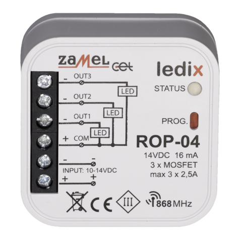
Zamel ledix ROP-04 User manual

Zamel
Zamel Exta Free ROM-10 User manual

Zamel
Zamel ROM-24 User manual

Zamel
Zamel SUPLA ROW-07 User manual