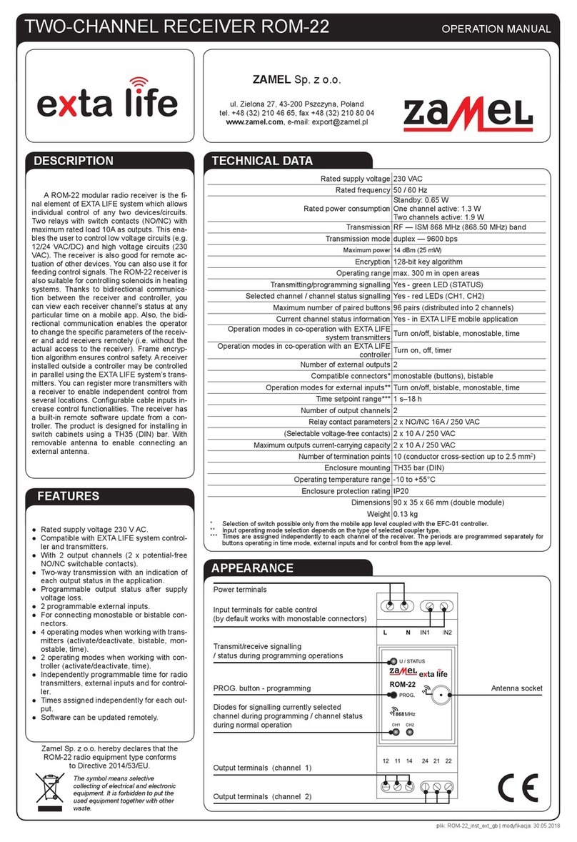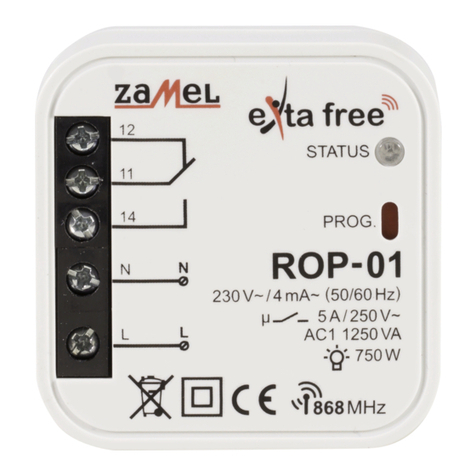
2-CHANNEL RADIO FLUSH RECEIVER
ROP-22
TECHNICAL DATA
Nominal supply voltage: 230 VAC
Nominal frequency: 50/60 Hz 50 / 60 Hz
Nominal power consumption:
0,45 W – standby
0,8 W – one channel operation
1,2 W – two channel operation
Transmission: radio – ISM band 868 MHz
Transmission way: two-way - 9600 bps
Coding: algorithm based on 128-bit key
Operating range: up to 330 m in the open area
Optical signalling
(transmission / programming): yes – RGB LED
Number of paired buttons: maximum 96 pairs
Current receiver’s mode information: yes – in the EXTA LIFE mobile application
Operating modes in cooperation
with EXTA LIFE system transmitters: switch on /switch off, bistable, monostable, time
Operating modes in cooperation
with EXTA LIFE controller: switching on, switching off, time
Number of external inputs: 2
Cooperation with push-buttons*: monostable (push-buttons), bistable
Operating modes for external inputs**: switching on, switching off, bistable, monostable,
time
Time adjustment range: 1 sec. ÷ 18 hrs.
Number of output channels: 1
Relay contact parameters: 2 x NO 5A / 250 VAC (voltage output)
Maximum output load:
incandescent and halogen lighting sources – 750 W
LEDs – 60 W
CFL lamps – 250 W
Number of terminal clamps: 6 (wires with cross-section up to 2,5 mm2)
Casing mounting: Ø60 mm junction box
Operating temperature range: -10 do +55 °C
Protection degree: IP20
Protection class: II
Dimensions: 47,5 x 47,5 x 20 mm
Weight: 0,04 kg
Reference standards: EN 60669, EN 60950, EN 61000
ETSI EN 300 220-1, ETSI EN 300 220-2
* switch type congured by means of the EXTA LIFE mobile application
** operating mode dependent on selected switch type
MOUNTING
• The ROP-22 receiver is designed to be mounted in a junction box. Its dimensions enable
ush (Ø60 minimum) and surface mounting. In case of a ush junction box, a deepened
box is recommended, as it makes mounting easy with a large number of wiring and a big
cross-section of connection wires.
• The device is designed for single-phase installation and must be installed in accordance
with standards valid in a particular country. The device should be connected according to
the details included in this manual instruction. Installation, connection and control should be
carried out by a qualied electrician staff, who act in accordance with the service manual
and the device functions. For safety reasons, do not mount the device without casing or with
a damaged one, as an electric shock may occur.
• After power supply has been applied, the receiver will carry out service activities for about
5 seconds (it is signalled by a green STATUS LED, it will ash at an interval of 1 second).
During this time the receiver’s control is not possible.
CAUTION: Before installation make sure the connection cables are not under voltage.
INSTALLATION:
1. Disconnect power supply by the phase fuse, the circuit-breaker or the switch-disconnector
combined to the proper circuit.
2. Check if there is no voltage on the connection cables by means of a special measuring
equipment.
3. Connect the device cables with the terminals in accordance with the installing diagram.
4. Install ROP-22 in a junction box.
5. Switch on the power supply from the mains.
MOUNTING REMARKS
1. Do not mount receivers in a close proximity to each other (if there is a possibility, keep a dis-
tance of minimum 15 cm between receivers). Particularly, avoid installation of one receiver
over the another.
2. The maximum output load must be obeyed:
• incandescent and halogen lamps: 750 W / channel,
• uorescent CFL lamps: 250 W / channel,
• dimmable LEDs: 60 W / channel.
3. During mounting, make sure the receiver is not exposed to direct water and operation in an
increased humidity environment. The mounting ambient temperature range should be within
the range from -10 to + 55 °C.
4. The ROP-22 receiver is designed to be mounted indoor. In case the receiver is mounted
outdoor, it must be placed in an additional hermetic casing.
5. Wired control switches can be connected to the IN1 and IN2 inputs of ROP-22 receiver. By
default, the inputs are adapted to cooperate with monostable push-buttons in a bistable
mode. It means t hat each subsequent impulse given to the IN1 or IN2 input causes the output
mode is changed to an opposite mode.
6. After a receiver has been installed, it is important to check, if it operates correctly. In case of
control by means of the EXTA LIFE system transmitters, they must be rst programmed with
a receiver (see Programming transmit ters). In case of cooperation with a controller, a correct
pairing of a receiver with a controller is required (see Register of receivers in the EXTA LIFE
system).
CAUTION: Input functionality (switch type, operation mode) can be changed by means
of the EXTA LIFE mobile application. It is necessary to install a controller in the system
and pair it with ROP-22 receiver – see Input functionality.
ROP-22_gb.indd 4-5 05.09.2017 07:43
