6
English
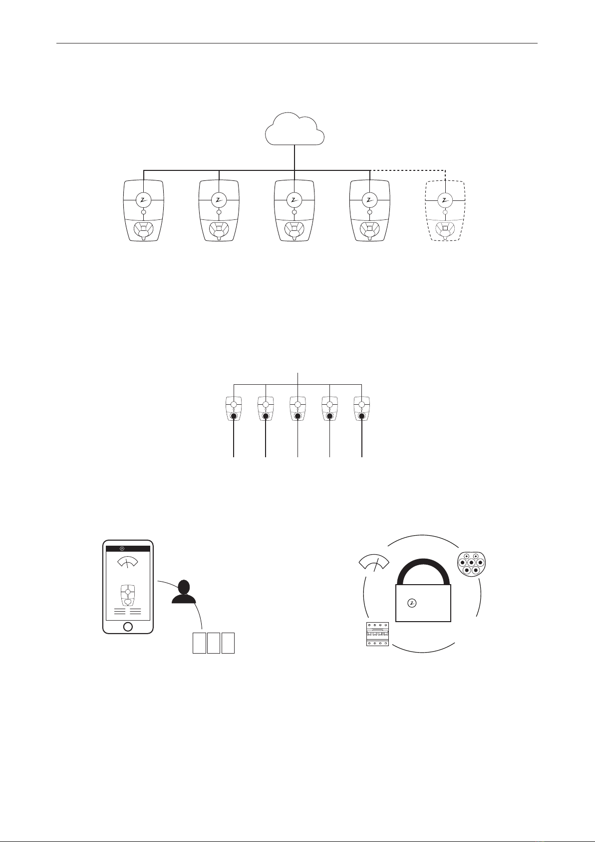
2. Description of the Zaptec Pro system
Useallavailablecapacity
The power is shared dynamically across all the charging
stations. Enables over 100 electric vehicles to be charged
in one day, via a single 63A* circuit breaker. Charge at up
to 22kW on all charging stations.
Uniquescopeforscalingwithasinglecircuit
andpowercable
Communication between the charging stations and the
cloud solution passes through the same power cable.
This shared infrastructure makes it possible to start
with a few charging stations and expand the system as
and when necessary. Scaling an existing installation will
therefore not require any extra work or investment in
electrical infrastructure.
Fair use throughRFIDorZaptecApp
A built-in electricity meter accurately records
energy consumption, which can then be allocated
toauthorised users.
* With three-phase connection and typical charging usage over 24 hours.
Safetyinaccordancewiththehigheststandards
Fully-rated Type 2 charging socket, circuit breaker,
electronic earth fault protection and temperature sensors
are built into the charging station. This ensures safety
forboth the user and the power grid.
Future-proofandintelligentchargingsolution
Combines power electronics, built-in software and a
cloud-hosted portal for configuration, monitoring and
control. The solution is future-proof, with software updates
delivered over-the-air to the charging station.
4G 4G 4G 4G
4G
kW
kr
199 kWh
2 3 3
4
Zaptec
4G
Zaptec