zarges MultiTower S-PLUS 1T Parts list manual


3
en
Contents
1 General information ......................................................................... 4
1.1 Introduction .....................................................................................4
1.2 Manufacturer ...................................................................................4
1.3 Type approval....................................................................................4
1.4 Warranty ..........................................................................................4
1.5 Date of issue.....................................................................................5
1.6 Copyright and trademark rights ......................................................5
1.7 Intended use ....................................................................................5
1.8 Improper use ....................................................................................5
2 Assembly ......................................................................................... 6
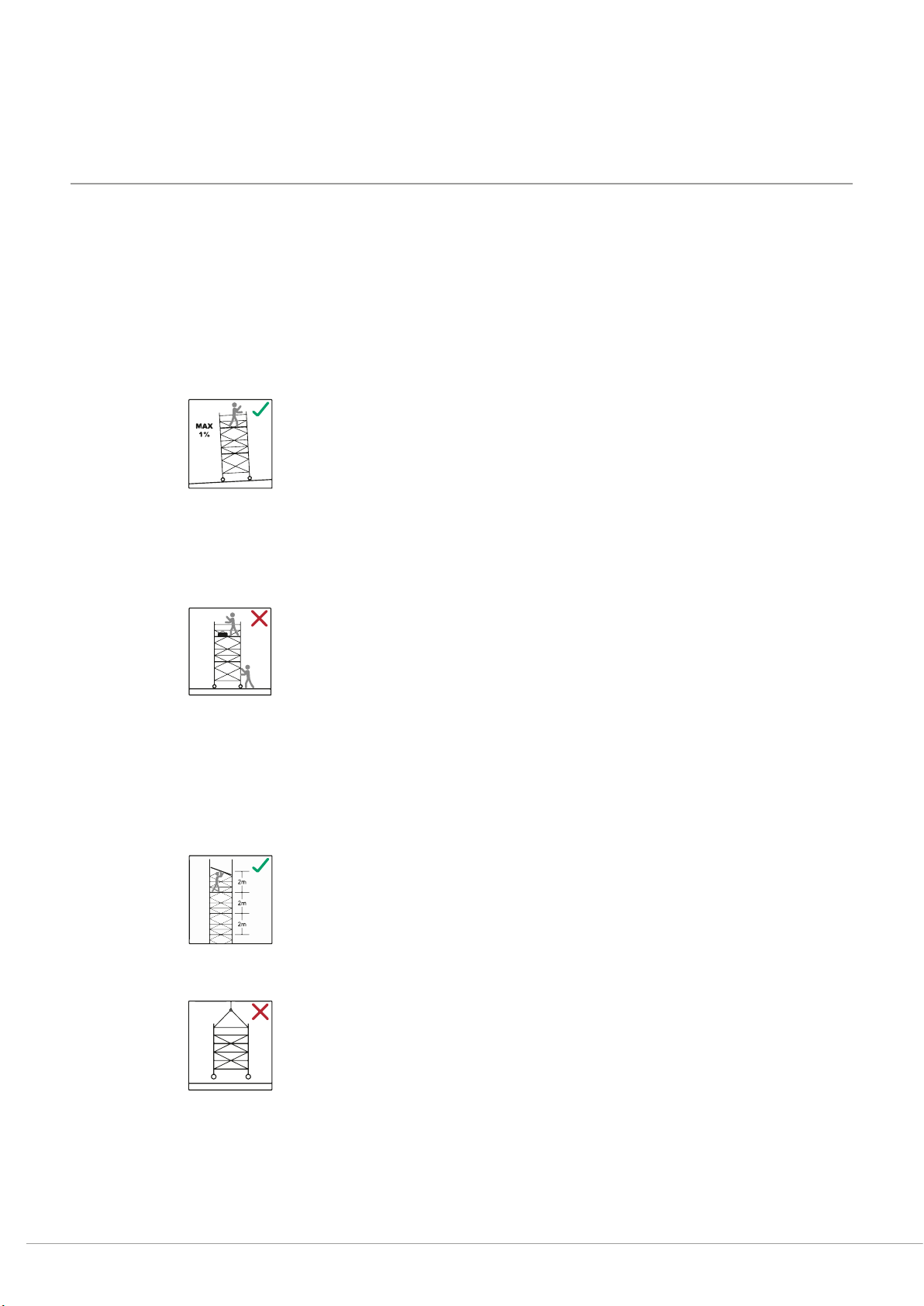
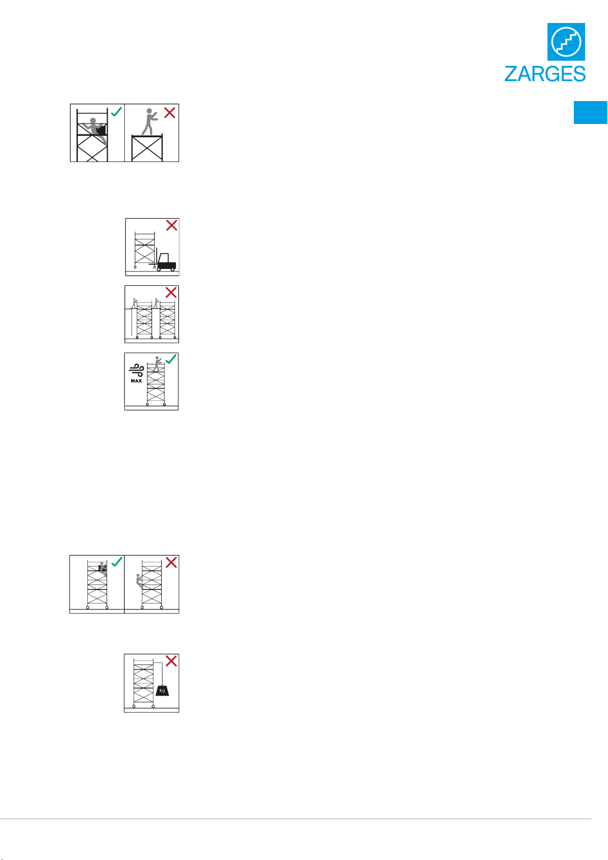
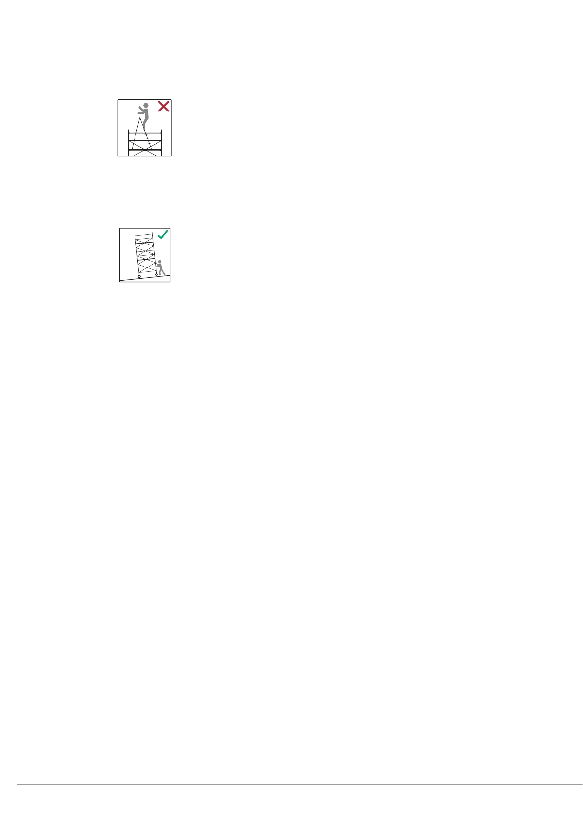
2.1 Safety regulations.............................................................................6
2.2 Usage regulations ...........................................................................7
2.3 Working on electrical equipment with the scaffold unit.................8
2.4 Other applicable safety instructions ............................................... 9
2.5 Technical data ..................................................................................9
2.6 General assembly instructions MultiTowerS-PLUS1T and 2T... 10
2.7 Overview of scaffolding types MultiTower S-PLUS 1T and 2T...... 15
2.8 General assembly instructions CompactMasterS-PLUS1T
and 2T.............................................................................................. 17
2.9 Overview of scaffolding types CompactMaster S-PLUS 1T
and 2T.............................................................................................. 24
2.10 Note on dismantling the scaffold tower ........................................ 25
2.11 Basic dimensions ...........................................................................26
2.12 Identification ...................................................................................28
2.13 Parts list incl. ballasting ................................................................29
2.14 Assembly drawings ........................................................................35
3 Structural safety regulations ......................................................... 37
3.1 General information ...................................................................... 37
3.2 Attaching the ballast ...................................................................... 37
3.3 Attaching the anti-twist device ..................................................... 37
3.4 Maintenance, servicing, storage and cleaning ............................. 38
3.5 Testing the scaffold unit components ........................................... 38
4 Spare parts..................................................................................... 40
en Assembly and Usage Instructions MultiTower S-PLUS 1T and 2T
CompactMaster S-PLUS 1T and 2T

4
1 General information
1.1 Introduction
These assembly and usage instructions apply exclusively to the scaffold units
described therein.
The notes on safety and the rules and regulations for handling scaffold units apply
to the scaffold towers referred to in this documentation.
The operating companies accept responsibility for the following points:
• adherence to local, regional and national regulations
• observance of the regulations (laws, ordinances, guidelines etc.) for safe handling
listed in these assembly and usage instructions
The operating company must ensure that the assembly and usage instructions are
available to the operating personnel and that the instructions, information, warnings
and safety regulations they contain are strictly observed.
If you require further information or if specific problems occur which are not
covered in sufficient detail in these assembly and usage instructions, please contact
the manufacturer directly (see Section 1.2).
1.2 Manufacturer
ZARGES GmbH Tel.: +49 8 81 / 68 71 00
Fax: +49 8 81 / 68 72 95
PO Box 16 30 Email: zarges@zarges.de
D-82360 Weilheim Internet: http://www.zarges.de
1.3 Type approval
The scaffold units described below have been tested by TÜV Süd (German Technical
Control Board South).
1.4 Warranty
The scope, period and form of the warranty are stipulated in the manufacturer's
sales and delivery conditions. The assembly and usage instructions valid at the time
of delivery apply to all warranty claims arising from insufficient documentation.
The following applies above and beyond the sales and delivery conditions:
themanufacturer accepts no liability for damage to the scaffold units arising from
one of more of the following:
• ignorance of or failure to observe these assembly and usage instructions
• insufficiently qualified or instructed operating personnel
• the use of parts other than original spare parts.

5
en
The operator bears sole responsibility for ensuring
• that the safety regulations are adhered to,
• that improper use (see Section 1.8), faulty setting up and impermissible operation
are excluded and thus
• ensuring that the equipment is put to its intended use (see Section 1.7) and
• that the scaffold units are operated in accordance with the application conditions
defined in the contract.
1.5 Date of issue
The date of issue of these English assembly and usage instructions is 01 May 2021.
1.6 Copyright and trademark rights
The copyright to these assembly and usage instructions lies with the manufacturer.
The manufacturer also reserves all further rights, in particular in the case of the
granting of a patent or utility patent registration.
Any infringement of the conditions described above will result in liability for damages!
1.7 Intended use
The scaffold units listed in these assembly and usage instructions may only be used
as scaffolding in accordance with the stipulations of EN 1004 and the overview of
models in these assembly and usage instructions.
1.8 Improper use
Misuse - that is, any use of the scaffold units documented in these assembly and
usage instructions which deviates from that described in Section 1.7 - shall be
deemed improper use as defined by the Product Safety Act.
This also applies to disregard of the listed standards and guidelines listed in these
assembly and usage instructions.

6
2 Assembly
2.1 Safety regulations
1. Do not stand on the frame of the folding unit! Use only platforms, the rungs
or a climbing aid to climb the scaffold unit.
2. Only undamaged and fault-free original spare parts for the manufacturer's
scaffold system referred to in the inspection certificate may be used.
Before using the scaffold units, all parts must be examined for correct
assembly and functionality.
3. The scaffold units may only be erected vertically on a horizontal and level
subsurface with sufficient load-bearing capacity.
If necessary, insert load-distributing pads under the unit. The surface on
which the scaffold unit is moved must be able to accommodate its weight.
4. Apply the roller brakes before using the scaffold unit.
Release the roller brakes before moving the scaffold unit.
5. Secure the scaffold unit with four stabilisers. When setting up the scaffold
unit against a wall, swing the stabilisers accordingly to prevent tipping.
When setting up the scaffold unit in a corner, secure it with three stabilisers.
6. The scaffold unit may only be moved by hand, in longitudinal or diagonal
direction and on a firm, level surface free of obstacles. The scaffold unit must
not be moved at more than normal walking speed. When moving the scaffold
unit, ensure that it does not touch live cables.
There may be no persons, material or tools on the platform when the
scaffold unit is moved. Avoid collisions.
When moving the scaffold unit, the platform height must not exceed 4 m.
Release the roller brakes before moving the scaffold unit.
7. The stipulations of EN 1004-1 “Mobile work platforms” apply to the structural
safety, erection and use of the aforementioned scaffold units.
8. The scaffold units may only be assembled and used by persons who are
familiar with these assembly and usage instructions.
9. The distance between the platforms must not exceed 2m during assembly
and dismantling.
10.According to EN 1004-1, the maximum platform heights are limited to 8 m
outdoors and 12 m in enclosed spaces.
11.The use of lifting tackle on the scaffold unit is not permitted.
12.For information on the use of ballast weights, stabilisers and stand-off
brackets to warrant stability, see these assembly and usage instructions.

7
en
13.Work on the working platform is only permitted with complete 3-part side
protection, i.e. guard-rail frames, knee protection and peripheral toeboards.
Toeboards are not necessary on the rest platforms.
14.When setting up the scaffold unit against a wall, stand-off brackets can also
be used in addition to ballast (accessory, Order No. 42920).
15.Working on several working platforms simultaneously is not permitted.
16.The permissible load capacity of the scaffold unit with evenly-distributed load
is 2.0 kN/ m² (in accordance with EN 1004-1 – scaffolding category 3).
17.Moving the scaffold unit with the assistance of vehicles (e.g. fork lifts) is
prohibited. The scaffold unit must not be lifted, pulled or pushed using a
forklift.
18.Bridging the gap between scaffold units and buildings by means of planks
etc. is not permitted.
The scaffold unit must not be used as a stair tower to reach other
constructions.
19.For use outdoors or in open buildings, the scaffold unit must be moved into a
wind-protected area where wind strengths exceed 6 (on the Beaufort scale),
in the case of an oncoming storm and when work has been completed,
or it must be protected against tipping with other suitable measures
(e.g.anchoring). At wind strengths exceeding 6 on the Beaufort scale (12m/s),
it becomes perceptibly difficult to walk forwards.
20.Before using the scaffold unit, its vertical alignment must be checked and
corrected if necessary.
21.The scaffold unit must be checked for correct and complete set-up.
22.The scaffold unit must not be used during lightning and thunderstorms.
23.Mobile work platforms must not be used as roof-edge protection.
2.2 Usage regulations
24.Personnel must ascend to work platforms from the inside only. Ascending
from the outside is only permitted up to platform heights of 2 m.
25.Personnel must not brace themselves against the side panels while working.
26.Jumping on the platforms is prohibited.
27.The generation of horizontal loads which could cause the scaffold unit to tip
over, for example through work on adjacent constructions, is prohibited.
28.Particular attention must be paid to wind conditions which might cause the
scaffold unit to tip over when it is used in buildings open to the passage of
wind, in uncovered buildings or at the corners of buildings.
6 BFT

8
29.The platform height must not be increased with the aid of ladders, crates or
other devices.
30.Tools and materials may only be handed upwards. Always take the weight
of tools and materials into consideration to avoid overloading the work
platform.
The person handing the load upwards must not let go of it until the person
receiving it has a firm hold on it.
31.Scaffold units with swivel castors can be wheeled to their final location after
assembly. The floor/ground gradient must not exceed 3%. Avoid collisions.
When the scaffold unit is in its final position, the alignment must be checked
again.
32.When moving the scaffold unit, always take care that it does not touch any
live equipment.
33.Electrical tools (drills etc.) may only be operated on the scaffold unit at Safety
Extra Low Voltage (48 V), with protective insulation (separation transformer)
or if they are connected with a ground fault circuit interrupter with a residual
current of 30 mA. The stipulations of BGI 594 must be complied with.
34.Tools and materials must be stored on the work platform in such a way that
there is a passageway of 20 cm at the sides of the work platform.
35.The permissible platform load must not be exceeded, regardless of the
number of persons (see “Technical data” on page9).
36.The horizontal load must not exceed 30 kg (e.g. leaning out or working on the
wall side with a hammer drill).
37.During assembly and dismantling the single parts should be handed
upwards and downwards as close as possible to the scaffold unit from level
to level by 2 persons.
38.The mobile work platform can, depending on its size, be assembled and
dismantled by one person, but two persons are recommended.
39.During assembly and dismantling ensure that all persons are secured by
theS-PLUS guardrail.
2.3 Working on electrical equipment with the scaffold unit
The scaffold unit must not be used to perform work on or in the vicinity of
unprotected live equipment unless
• the section of the equipment in question has been disconnected,
• the section of the equipment in question has been secured against being switched
back on,
• the section of the equipment in question has been checked to ensure that it is
notlive,
• the section of the equipment in question has been short-circuited with a
grounding bar and
• the section of the equipment in question has been shielded against adjacent
liveparts.
3%
MAX

9
en
2.4 Other applicable safety instructions
The stipulations of DGUV information sheet 201-011 "Instructions for the Handling
of Work Scaffolds and Protection Scaffolds" apply for the inspection, assembly and
use of the scaffold unit.
BGV C22 and the stipulations of DGUV information sheet 203-004 "Safety rules for
the use of electrical equipment in the case of increased electrical hazard" apply
when using electrical equipment on the scaffold unit.
2.5 Technical data
If several platforms of the scaffold unit are subjected to load, the total load of the
scaffold unit must not exceed a weight of 500 kg.
MultiTowerS-PLUS1T, single platform 0.75 x 1.80 m / 2.50 m
Approved in accordance with EN 1004-1 Scaffolding category 3
Permissible load in accordance with scaffolding category 3 200 kg/m²
Maximum total load of the scaffold unit 202 kg / 286 kg
Maximum platform load 202 kg / 286 kg
Maximum platform height 13.20 m
MultiTowerS-PLUS2T, double platform 1.35 x 1.80 m / 2.50 m
Approved in accordance with EN 1004-1 Scaffolding category 3
Permissible load in accordance with scaffolding category 3 200 kg/m²
Maximum total load of the scaffold unit 404 kg / 572 kg
Maximum platform load 404 kg / 572 kg
Maximum platform height 13.20 m
CompactMasterS-PLUS1T, single platform 0.85 x 1.80 m
Approved in accordance with EN 1004-1 Scaffolding category 3
Permissible load in accordance with scaffolding category 3 200 kg/m²
Maximum total load of the scaffold unit 202 kg
Maximum platform load 202 kg
Maximum platform height 13.55 m
CompactMasterS-PLUS2T, double platform 1.45 x 1.80 m
Approved in accordance with EN 1004-1 Scaffolding category 3
Permissible load in accordance with scaffolding category 3 200 kg/m²
Maximum total load of the scaffold unit 202 kg
Maximum platform load 202 kg
Maximum platform height 13.55 m

10
2.6 General assembly instructions MultiTowerS-PLUS1T and 2T
The illustrations show a set-up with single platform. Assembly is identical for a
double platform. Assembly is identical for all platform lengths (1.80 m / 2.50 m).
For the height of the push-on
end frame (1 m or 2 m), see
“Overview of scaffolding types
MultiTower S-PLUS 1T and 2T”
on page15.
1. Insert the swivel
castors into the
push-on end frame
and fasten them with
omega springs.
The horizontal braces are
only required for specific
scaffolding types, (see
“Overview of scaffolding types
MultiTower S-PLUS 1T and 2T”
on page15).
2a. Connect push-on end
frame with horizontal
braces.
Attach horizontal
braces to the first rung.

11
en
The basic braces are
only required for specific
scaffolding types, (see
“Overview of scaffolding types
MultiTower S-PLUS 1T and 2T”
on page15).
2b. Connect push-on
end frame with basic
braces.
Attach basic braces
above and below the
first rung.
3. Attach and fasten the
2m push-on end frame
on both sides.
1
2
2

13
en
6. Insert platform and
lock it at two opposite
points.
1
2
7. Align the scaffold unit
using a spirit level.
8. Fit all four stabilisers.
For the position of the
stabilisers, see “Basic
dimensions” on page26.
1
2
9. Attach the ballast
weights, if required.
For ballast weights, see
“Parts list incl. ballasting” on
page29.

14
10. Repeat steps 3, 5 and 6
until the scaffold height
is reached.
11. Attach the top platform
in the centre and lock it
at two opposite points.
3
1
1
2
12. Insert both end
toeboards (U-profiles
are open towards
thetop).
13. Push in the side
toeboards on both
sides.

15
en
14. Hook in stirrup step.
2.7 Overview of scaffolding types MultiTower S-PLUS 1T and 2T
1 m push-on end frame
The following scaffold towers are equipped with 1 m push-on end frames above the
swivel castors.
Length Braces / platform Rungs
1.80 m 2.50 m
Single platform
52235 52236
a1
a2
h1
h2
p1
1 to 5
1 to 5
1 to 1
1 to 1
7
52255 52256
52275 52276
52295 52296 a1
a2
b1
b2
p1
1 to 5
1 to 5
1 to 1
1 to 1
7
52315 52316
Double platform
52435 52436 a1
a2
h1
h2
p1
1 to 5
1 to 5
1 to 1
1 to 1
7
52455 52456
52475 52476
a1
a2
b1
b2
p1
1 to 5
1 to 5
1 to 1
1 to 1
7
52495 52496
52515 52516
b1
h1
h2
b2
a2
p1
a1
Legend
a: Diagonal brace
b: Basic brace
h: Horizontal brace
p1: bottommost platform

16
2 m- push-on end frame
The following scaffold towers are equipped with 2 m push-on end frames above the
swivel castors.
Length Braces / platform Rungs
1.80 m 2.50 m
Single platform
52225 52226
h1
h2
p1
1 to 1
1 to 1
3
52245 52246
52265 52266
52285 52286
b1
b2
p1
1 to 1
1 to 1
3
52305 52306
52325 52326
Double platform
52425 52426
h1
h2
p1
1 to 1
1 to 1
3
52445 52446
52465 52466
52485 52486
b1
b2
p1
1 to 1
1 to 1
3
52505 52506
52525 52526
b1
h1
h2
b2
p1
Legend
b: Basic brace
h: Horizontal brace
p1: bottommost platform

17
en
2.8 General assembly instructions CompactMasterS-PLUS1T and 2T
The illustrations show a set-up with single platform. Assembly is identical for a
double platform.
1. Insert the swivel
castors into the folding
unit and fasten them
with omega springs.
2. Pull the folding unit
out fully until the
hinge snaps into place
audibly.

18
The following step only applies
for specific scaffolding types,
(see “Overview of scaffolding
types CompactMaster S-PLUS
1T and 2T” on page24).
3a. Fasten the horizontal
brace to the lowest
rung.
The following step only applies
for specific scaffolding types,
(see “Overview of scaffolding
types CompactMaster S-PLUS
1T and 2T” on page24).
3b. Insert platform at the
lowest rung and lock it
at two opposite points.
1
2

19
en
For the height of the push-on
end frame (1 m or 2 m), see
“Overview of scaffolding types
CompactMaster S-PLUS 1T and
2T” on page24.
4. Attach and fasten the
push-on end frame on
both sides.
1
2
2
a
The following steps, 5aa to
5ac, only apply for specific
scaffolding types, (see
“Overview of scaffolding types
CompactMaster S-PLUS 1T and
2T” on page24).
5aa.Insert advanced
guardrail at the top
rung on the folding
frame side and lock.
1
2

20
5ab.Insert platform and
lock it at two opposite
points.
1
2
5ac. Insert advanced
guardrail at the top
rung on the opposite
side from the folding
frame and lock.
1
2
This manual suits for next models
3
Table of contents
Other zarges Construction Equipment manuals

zarges
zarges Z200 Parts list manual

zarges
zarges PaxTower S-PLUS 1T Quick setup guide

zarges
zarges PAXTower 3T 5535122 User manual

zarges
zarges 21004431 Product guide

zarges
zarges PaxTower S-PLUS 1T Quick setup guide

zarges
zarges Z600 S-PLUS Parts list manual

zarges
zarges Skymaste Industrial Z600 Parts list manual

zarges
zarges Z 600 S-PLUS Parts list manual

zarges
zarges 53794 User manual