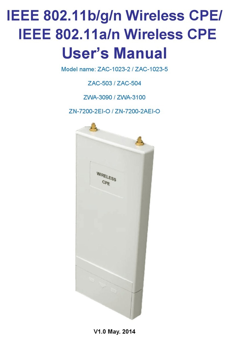
ZComax AIRRUNNER CPE-2 Series User manual

CPE-25(x) Series
OEM INSTALLERS
QUICK START GUIDE
AIRRUNNER
CPE

Preface
The CPE-2(x) series modular 802.11b wireless
radio solution was designed to meet the growing
needs of The ISP, System Integrator and other
professional developers. The CPE-2(x) series
product is intended for long distance point to
point communications over the wireless medium.
This manual will demonstrate how the
equipment is to be used in a safe an lawful
manner.
** IMPORTANT **
The installation of the PCMCIA module into an
enclosure requires that the integrator label the
outside of the enclosure with the FCC ID
printed on the module.
Changes or modifications not expressly
approved by Zcomax Technologies, Inc. may
void the user’s authority to operate the
equipment.
“Note: This equipment has been tested and
found to comply with the limits for a Class A
digital device, pursuant to Part 15 of the FCC
Rules. These limits are designed to provide
reasonable protection against harmful
interference when the equipment is operated in
a commercial environment. This equipment
generates uses and can radiate frequency
energy and, if not installed and used in
accordance with the instruction manual, may
cause harmful interference to radio
communications. Operation of this equipment in
a residential area is likely to cause harmful
interference in which case the user will be
required to correct the interference at his own
expense”.
HEAT
oThe product should be situated
away from heat sources such as
radiators, heat registers, stoves, or
other appliances (including
amplifiers) that produce heat.
OUTDOOR ANTENNA GROUNDING
oBe sure the product is grounded
so as to provide some protection
against voltage surges and built
up static charges.
oSection 810 of the National
Electrical Code (NEC),
ANSI/NFPA No. 70-1990,
provides information with respect
to proper grounding of the mast
and supporting structure,
grounding of the lead-in wire to
an antenna-discharge unit, size
of grounding conductors,
location of antenna-discharge
unit, connection to ground
electrodes, and requirements for
the grounding electrode.
oNote to Installer: This
reminder is provided to call
the installer’s attention to
article 820-40 of the NEC that
provide guidelines for proper
grounding and in particular,
specifies that the cable ground
should be connected to the
grounding system of the
building, as close to the point
of cable entry as practical.
DAMAGE REQUIRING SERVICE
oThis product should be serviced
by qualified service personnel
when:
The power supply cord or
plug has been damaged,
or
An object or liquid has
entered into the product,
or
The product does not
operate normally or
exhibits a marked
changed in performance,
or
The product has been
dropped, or the enclosure
has been damaged.
This product should only be installed
by a qualified professional.
The CPE device MUST be installed to
provide a separation distance of at
least 35cm from all persons and must
not be collocated or operating in
FCC STATEMENT
IMPORTANT SAFETY INSTRUCTIONS

conjunction with any other transmitter or
antenna
Check Product Contents.
Check product for complete contents.
The following items should be
included in the box.
a. CPE-2(x) Series ( See
components of CPE)
b. AC Adaptor*
c. Power Injector*
d. 6’ Category-5 Cable*
e. 5” Category-5 patch cable
f. Category 5 feed line 1-300’
g. Software CD
h. This Guide
i. Mast-mount Hardware:
i. Brackets x 2
ii. Clamps x 2
iii. Screws x 4
iv. Washers x 8
v. Nuts x 4
WARNING: Items “b”, “c” and “d” are
for indoor-use only.
Components of CPE:
oSingle board computer (SBC) – The
SBC is a ARM PCMCIA Platform that
is used to interface with the RF PC Card.
It is used to control the PCMCIA
firmware as well as Convert all Ethernet
802.3 packets to wireless 802.11b, using
the PCMCIA Card.
oWireless RF card – The PCMCIA card
is an 802.11b wireless radio module that
is used to transmit all data intended for
the link it is attached to.
oAntenna – The PCB panel antenna is
tuned for the 2.4 – 2.8 frequency range.
It comes in two sizes, 15dBi and an
18dBi. The antenna selection is used to
determine the out power needed to
establish a reliable connection.
Configuration:
Connections
oThe PCMCIA Card is inserted into SBC,
The PCMCIA rails are keyed so as to avert a
wrong insertion method.
oThe Antenna feed line is terminated with
an MMCX reverse polarity plug that is
used to connect to the PCMCIA’s
primary antenna jack (Jack closets to the
PCMCIA’s LEDs.
Mounting
oThe antenna can be mounted with the
use four predrilled mounting holes to
assure it will be firmly held in place
oThe SBC has four mounting holes that
are grounded to the main electrical
ground of the SBC.
oThe POE splitter has pre drilled
mounting holes that allow it to be firmly
held in place
Cable connections
oThe 6” Category 5 patch cable is used to
connect to the SBC’s ethernet jack and
the POE splitters Etherent jack.
oThe DC power cord is used to connect
the DC splitter board (main power feed)
to the SBC’s dc jack.
oThe main Ethernet feed line can now be
connected to the input Ethernet jack
located on the POE splitter and
connected to the DC injector box, once
in place the compression fitting cap can
be tightened.
oThe 6’ Category 5 patch cable can now
be connected to the main Ethernet
connector located on the desired device.
oThe device is now connected and ready
to go.

1. Gather Basic Information.
Gather the following information and
write it in the space provided for future
reference. Enter “NA” for not applicable.
Refer to end of this Guide for sample
configurations.
j. Password:__default_____________
k. ESSID: _________________
l. IP Address: _________________
m. Netmask: _________________
n. Gateway: _________________
o. Enable DHCP client:
YES ___ NO ___
p. Enable Internal Router:
YES ___ NO ___
q. Internal Router’s WAN Port on:
WLAN ____
Ethernet _____
r. NAT:
YES _______ NO_________
Internal Router’s LAN port IP address:
___________________
s. Internal Router’s LAN port Netmask:
___________________
t. Enable Internal DHCP server:
YES ________ NO ______
Begin IP_________________
End IP__________________
Netmask________________
Gateway________________
Primary DNS_____________
Secondary DNS___________
Primary WINS ____________
Secondary WINS _________
WEP Key: _______________________
2. Install Software.
Install the software on a PC connected to the
same Ethernet segment as the product.
a. Insert the CD into your CD-ROM
drive. Run SETUP.EXE from the
CD's root directory.
b. Follow the on-screen prompts to
install the software on to your
system.
3. Connect All Cables.
Connect cables as follows:
a. Insert the Category-5 cable to the
Power Injector port marked
"NETWORK". Insert the other end of
the cable to an Ethernet hub.
b. Insert the CPE-250HP's RJ-45
connector to the Power Injector port
marked "CPE".
c. Insert the AC adaptor connector to
the Power Injector port marked "DC
In". Insert the AC adaptor to a wall
AC outlet. The Power LED on the
CPE-250HP should turn on.
4. Configure Product.
On a PC that is attached to the same
Ethernet segment as the CPE-250HP, run
the installed CPE-250 Manager software to
configure the product.
a. On the Windows desktop, click on
START|PROGRAMS|ZCOMAX CPE-250
MANAGER/CPE-250 MANAGER to start
the software.
b. Once started, the CPE-250
Manager will browse the Ethernet
segment to locate any attached
CPE-250HP Series products. It will
display all CPE-250HP units that it
can locate during this discovery
process. Each CPE-250HP unit is
displayed in the form of an icon with
its default name listed below. This
default name is formed by
concatenating "AP" with the last 6
numbers of the CPE-250HP's MAC
address (example: AP123456).
INSTALLATION

c. Double click on the CPE-250HP
product you wish to configure.
d. Enter “default” at the password
prompt.
e. Once logged into the CPE-250HP,
the software will display the main
screen. Click on the tab labeled
"CONFIGURATION".
f. The
CONFIGURATION screen is now
displayed. Click on the tab labeled
"IEEE 802.11".
g. The
IEEE 802.11 screen is now
displayed.
h. Enter the ESSID you have gathered
from Step 2. Do not click on the
"APPLY" button now.
i. Click on the tab labeled "IP Address".
j. If you would like to enable the
internal router, select "IP Router" in
the TCP/IP mode selection box and
continue to the next step.
Otherwise choose "Bridge Only" and
perform the following two sub-steps:
i. Enter the IP Address
information from Step 2, or
choose to use DHCP to
automatically obtain IP
address, netmask and
gateway information from a
DHCP server by clicking on
the "DHCP status" radio
button.
ii. Skip the steps below by
continuing onto Step “v”.
k. Configure the router's WAN port
using information from Step 2 by
clicking on one of the following two
radio buttons:
i. WAN on WLA (WLAN)
ii. WAN on Eth (Ethernet)
l. Click on the "SETUP” button just
ABOVE the radio buttons in Step “l”
(above) to setup the WAN port.
m. A new window pops up over the
current window. Click on the
"Manual" radio button to manually
configure the WAN port's IP address,
netmask, and gateway. Or click on
the "DHCP" radio button to
automatically assign IP address,
netmask, and gateway information
from a DHCP server.
n. If Network Address Translation
(NAT) is required (i.e., private LAN)
place a check mark next to "NAT (IP
Sharing) through this port".
o. Click on the "Close" button to close
this pop-up window.
p. You are now returned to the original
IP Address tab window. Click on the
"SETUP" button BELOW the WAN
port radio buttons (WAN on WLA,
WAN on ETH) to setup the LAN port.
q. A new windows pops over the
current windows. Enter the Router's
LAN port IP Address and netmask.
r. If you would like to use the built-in
DHCP server to centrally assign IP
resources to PCs on the private
LAN, place a check mark next to
"Enable DHCP server".
s. Enter the Start and End IP address
for the DHCP server to assign to
DHCP clients on the private LAN.
t. Enter netmask, gateway, DNS and
WINS server information for the
DHCP server to assign, or click on
the radio buttons under "Use DHCP
Wizard" to automatically obtain this
information from the WAN port.
u. Click on the "Close" button to close
this pop-up window.
v. Click on the tab labeled "WEP".
w. The
WEP screen is now displayed.
x. If WEP is required, enter WEP key
from information gathered in Step 2.
y. The product is now fully configured.
Click the "Apply" button. The
software will prompt you that the
product will reset to apply the
changes. Click on the "YES" button
to reset the product. Click on the
“LOGOFF” icon to exit the software.
5. Change The Default Password.
It is recommended that you change the
default password. To change the password,
run the CPE-250 Manager software and
login with the default password (“default”).
Click on the tab labeled “CONFIGURATION”.
Within the CONFIGURATION screen, click on
the tab labeled “ADMINISTRATION”. Enter the
new password in both “New Password” and
“Confirm Change” text boxes. Click on the
“APPLY” button. The software prompts that
the product will reset for the changes to take

effect. Click on the “YES” button to reset
the product. It is recommended that you
confirm this change by logging in with the
new password.
The product can be managed via any one of the
following three methods. Refer to the Users
Manual for complete details.
CPE-250 Manager: Run the CPE-250
Manager Software. Default password:
default.
Web-based Management: Point your
browser at the Product’s IP address (default
IP address: 192.168.1.1; Default password:
default).
Telnet: Open a Telnet session at the
product’s IP address (default IP address:
192.168.1.1; Default password: default).
Copyright 2002 Zcomax Technologies, Inc. All rights reserved.
P/N: QSG15-130. Rev 1.3
Zcomax and AirRunner are registered trademarks
All other registered marks are the property of
their respective owners
MANAGING THE CPE
This manual suits for next models
1
Table of contents
Other ZComax Wireless Access Point manuals
Popular Wireless Access Point manuals by other brands

Cisco
Cisco Aironet 2600 Series Getting started guide

Juniper
Juniper Mist AP32 Deployment guide

Formosa
Formosa AG-3621 manual

NETGEAR
NETGEAR WAG302 - ProSafe Dual Band Wireless Access... Reference manual

Netgate
Netgate Wireless Multi-Client Bridge user manual

Beijer Electronics
Beijer Electronics JetWave 4020 Series user manual