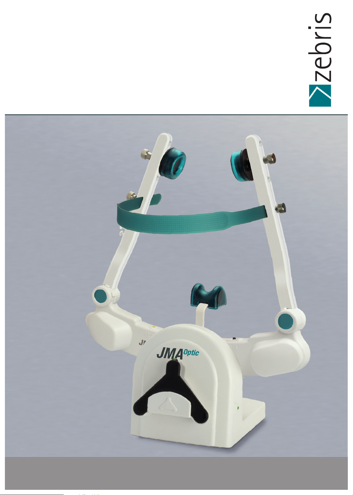
zebris JMAOptic Instruction manual

User Manual and technical data
JMAOptic

2797
Seite 2/69
Page 2/47JMA-Optic
Hardware User Manual
JMAOptic
© 2021 zebris Medical GmbH
All rights reserved. Reproduction in whole or in part only with the permission
of zebris Medical GmbH.
Textrelease: R2
Date: 07.05.2021
REF: 79011105
Illustrations of this manual may differ.
Manufacturer
zebris Medical GmbH Phone +49 (0) 7562 9726 - 300
Am Galgenbühl 14 Fax +49 (0) 7562 9726 - 50
Germany web www.zebris.de
Support
zebris Medical GmbH Phone +49 (0) 7562 9726 - 300
Am Galgenbühl 14 Fax +49 (0) 7562 9726 - 50
Germany web www.zebris.de
Please always provide the serial number of the product for inquiries!

Seite 3/69
Page 3/47JMA-Optic
Table of content
1 User information
1.1. Configuration of the user manual
1.2. Target group
1.3. Symbols used on products, packaging and user manual
2 Area of use and safety
2.1. Intended use
2.1.1. Use
2.1.2. Data export
2.1.3. Produkt life
2.2. Safety
2.2.1. Environmental conditions
2.2.2. Transport and storage
2.2.3. Obligations of user
2.2.4. General safety information
2.2.5. Safety information on heart pacemakers/defibrillators
2.2.6. Prohibited use
3 Produkt description
3.1. System components
3.2. Funktional principle of the JMA-Optic system
3.3. Elements of the JMA-Optic system
3.4. JMA-Optic Face Bow
3.4.1. Technical data
3.4.2. Type plate of the JMA-Optic Face Bow
3.4.3. State LED's
3.5. UK-Sensor OJM-UK1 (Lower Jaw Sensor)
3.5.1. Technical data
3.5.2. State LED
3.5.3. Changing the battery
3.5.4. Type plate OJM-UK1
3.6. Induktive Charger JMA-Optic
3.6.1. Technical data
3.6.2. State LED
6
6
6
7
8
8
8
8
8
9
9
9
10
11
12
12
13
13
13
14
15
16
16
17
18
18
18
19
19
20
20
20

Seite 4/69
Page 4/47JMA-Optic
3.7. IR-FS / IR Foot Switch
3.7.1. Technical data
3.7.2. State LED
3.7.3. Changing the battery
4 Accessories and spare parts
4.1. Hardware
4.2. Software
5 Putting the system into operation
5.1. Power supply and charging the batteries
5.2. UK-Sensor OJM-UK1 (Lower Jaw Sensor)
5.3. IT security and software installation
6 Decommission the system
7 Funktional checks and disposal
7.1. Regular checks and safety checks
7.2. Kontrolling the measurement function
7.3. Troubleshooting
7.4. Checklist for the recording of error messages
7.5. Disposal
7.5.1. Packaging
7.5.2. Disposal of electronic waste
7.5.3. Akkumulators und batteries
8 Preparation
8.1. Manual pretreatment
8.2. Manual cleaning and disinfection
8.3. Mechanical cleaning and disinfection
8.4. Control
8.5. Packing
8.6. Sterilization
8.7. Reusability
8.8. Summary table
21
21
21
22
23
23
27
28
28
29
29
30
31
31
32
33
33
34
34
34
34
35
35
36
38
39
41
40
40
41

Seite 5/69
Page 5/47JMA-Optic
9 Safety standards and system classification
9.1. Classificatio pursuant to appendix IX of the directive 93/42/EEC
9.2. Safety of medical electrical devices
9.2.1. Connecting the system to other electrical devices
9.2.2. Environment of the patient
9.2.3. Multiple sockets
9.3. Electromagnetic compatibility guideline
42
42
42
42
42
43
44

Please read this instruction carefully before using the product for the first
time to avoid operating errors and damage.
The exact adherence to the instructions in all sections of the operating
Instructions forthe measuring system is a precondition for its intended use.
Seite 6/69
Page 6/47JMA-Optic
User information
1.1. Configuration of the instructions for use
The instructions for use of the JMA-Optic consists of several parts:
1. Installation instructions for the WINJAW+ software, also contains your license code,
2. Technical specifications and instructions for use of the JMA-Optic hardware,
3. Instructions for us of the application software WINJAW+
The part technical specifications and instructions for use of the JMA-Optic hardware primarily
contains information on technical data and the operation of the JMA-Optic system as well as
information on its safe operation in combination with the patient accessories such as bite fork
or jaw attachment.
Information concerning accessory components is limited to key safety and maintenance
measures and/or hygiene measures.
The software and hardware usage instructions can be viewed in the WINJAW+ software as
online help (F1 key).
In addition, the documents are available on the enclosed installation media as well as online at
https://www.zebris.de/infomenue/downloads/
1.2. Target Group
This document is intended for dentists, practice staff and service personnel.

2797
REF
SN
LOT
MD
HIBC
Seite 7/69
Page 7/47JMA-Optic
Warning instructions designate a potential danger to the health and safety of users
and/or patients. The instructions explain the type of danger and how it can be avoided.
Notices designate a potential danger that can cause damage to the device.
The instructions explain the type of danger and how it can be avoided.
CE mark according to EC directive 93/42 medical devices
Manufacturer
Date of manufacture
Type BF device corresponding to DIN EN 60601-1
HF-transmitter (WiFi)
USB port
Direct Current
Do not dispose of in household waste
Refer to instructions for use.
Item number
Serial number
Lot number
UDI with HIBC code
Medical device
Accessories intended for single use on a single
patient during a treatment.
1.3. Symbols used on products, packaging and instructions for use

Seite 8/69
Page 8/47JMA-Optic
2 Area of use and safety
2.1. Intended use
The JMA-Optic system captures the individual mandibular movements of the patient by optical
triangulation.
From the movement data, parameters are calculated and visualized, which serve to assist in the
design of functional dentures and bite splints.
The JMA-Optic systems also is able to calculate functional parameters for the programming of
virtual and mechanical articulators and export of data for further processing with CAD/CAM
or CBCT systems.
Furthermore, the system allows the therapeutic positioning of the mandible in a jaw relation.
The JMA-Optic system must be used by trained dentists and it’s application environment is
limited to dental facilities. A typical measurement is performed within 15 minutes.
Patients must be able to mentally follow the operators instructions exactly.
The device must not be used on open wounds in the oral and head area.
2.1.1. Use
The system consists of face bow and lower jaw sensor. The face bow is placed on the patient’s
head and is supported on the nose. The lower jaw sensor is temporarily fixed with an accessory
on the lower jaw. Subsequently, a measurement can be performed.
Through the visualization of positions and movements, disorders of the dental-oral-jaw system
(stomatognathic system) can be determined.
Functional analysis can be used to determine both discoordinations and movement limitations as
well as a neuromuscular jaw relation.
The system software calculation of adjustment data of fully adjustable articulators. It supports
several well established articulators.
Interfaces for data export enable the use of the movement data recorded by the JMA-Optic in
CAD/CAM systems and CBCT systems for the functional optimization of dental prostheses and
bite splints.
The use of the JMA-Optic is only permitted as an additional diagnostic tool. Measurements must
be verified by means of additional measures before invasive procedures are taken.
2.1.2. Data export
The XML export function allows the use of determined jaw movements in CAD/CAM systems and
CBCT systems for functional optimization of dentures and occlusal splints. As a reference for data
matching serves a bite fork. This carries reference marks which can be detected by imaging systems
such as surface scanner or CBCT.
2.1.3. Product life
Provided that the WINJAW+ software and the operating system of the measurement PC are kept
up to date, a product life of 10 years can be expected.

The JMA-Optic contains lithium-ion batteries. When shipping the JMA-Optic,
transport instructions for Li-ion batteries must be adhered to. Additionally:
Labeling of the transport packaging according to valid regulations.
Storage at temperatures > 70°C can lead to premature aging of the
installed batteries.
The devices may not be operated in wet zones, damp areas, climatic
chambers, under-pressure-, overpressure-, or height-chambers.
The system is not intended for use in areas where there is a risk of
explosion, rooms used for medical purposes or in a flammable atmos-
phere (oxygen-enriched).
The devices should not be used near engines or transformers with a big
connected load, for example, or heavy current power lines, as electrical
or magnetic interference fields can distort the correct measurements
and/or render them impossible.
Do not operate the device in the immediate vicinity of heat sources
(radiators) or in direct sunlight, because IR radiation could affect the
accuracy of the measurements.
Seite 9/69
Page 9/47JMA-Optic
2.2. Safety
2.2.1. Environmental conditions
The JMA-Optic is suitable for use in dry interior rooms, as can be found in clinics,
medical practices and laboratories.
Temperature: 0°C to +45°C
Air pressure: 700 - 1100 hPa
Relative humidity: max. 85%, non condensing
2.2.2. Storage and transport
Storage and transport of the JMA-Optic should only be carried out in the original packaging
(hard case) provided by the manufacturer.
Temperature: -20°C to +70°C
Relative humidity: max. 95%, non condensing
Protect from moisture

Seite 10/69
Page 10/47JMA-Optic
2.2.3. Obligations of the user
It is the obligation of the user:
■
The general guidelines and/or national legislation, national regulations and technical
r
egulations pertaining to medical products are to be applied and fulfilled both during
installation and operation of the product appropriate to the stated intended use.
■ To comply with all the safety instructions stated in the operating instructions.
■ To carry out all of the inspection and maintenance work regularly as specified in the
operating instructions.
■ To only use fault free working equipment.
■
To ensure that the device is functionally safe and in a proper state prior to every use of the device.
■ To ensure all the provided operating instructions that which art part of the measurement
system, are kept within close range of the measurement system and are accessible to users
at all time.
■ To protect oneself, the patients and third parties against dangers.
■ To prevent a contamination occurring by the product.
During use, it is necessary to comply with the legal regulations especially:
■ The current work safety regulations.
■ The current accident prevention measures.
Responsibility for safety, reliability and effective performance of the JMA-Optic is assumed in case:
■ Assembly work, extensions, new setting, changes or repairs are carried out by trained
technicians or dealers explicitly authorized by the manufacturer.
■ The product operated in compliance with the operating instructions.
■ The information technology components provided by the user comply with the technical
requirements for hardware and software lined out in these operating instructions, and that
they are installed and set up according to the applicable instructions for these components.
■ The place of installation corresponds with the specified environmental conditions for the
measurement system and the current installation regulations.
■ Only the software made available by the manufacturer, as well as the components and
accessory parts listed in these operating instructions are used with the system.

Seite 11/69
Page 11/47JMA-Optic
2.2.4. General safety information
■ The use and operation of the system and the evaluation of measurement data and
its interpretation should only be carried out by trained specialist personnel.
The manufacturer assumes no liability for damage to persons or property, or the loss
of data that may occur due to the improper use of the software, the device, or its accessory parts.
■ Patients and measurement data may only be copied, moved or deleted with the help of the
database function that is provided by the zebris software application. In the case of the
deliberate changing of data without the database function, the user alone bears the full risk.
■ Before reinstalling and updating the software, a backup of the database must be created. After
data records have been imported, the integrity of the database must be validated by the user.
■ All measurement and/or analysis results should always be interpreted by a trained specialist and
checked for their relevance in consideration of the clinical medical history of the patient and in the
context of the further diagnostic procedure. If invasive measures are taken, the measurement
system should only be used as an additional assessment method. Under no circumstances can or
should invasive surgery or measures that put the patient at risk be carried out based on the
measurement results alone.
■ The measuring system must be checked at regular intervals to make sure it is functioning
properly. More details on this can be found in the section: 7 Funktional checks and disposal, p.31
in this user manual.
■ Ensure that all power and connection cables are routed and protected so that nobody is able
to trip over them. Check all cables and connection plugs regularly for damage. Damaged power
supply units, plug connectors and cables must be replaced before further use.
■ The measurement system is not protected against the penetration of fluids. If fluid penetrates
the measurement system, switch it off and please contact the technical service team of your sales
partner.
■ Never insert objects into components of the measurement system.
■
Before starting every measurement, it is necessary to ensure the correct choice and correct position
face bow and lower jaw sensor. The cables or the application aids can present a risk of injury to
the patient. In this context, please consult the special instructions in the handbooks of the appli-
cation software, and do not allow children or mentally impaired patients to enter the proximity
of the device without supervision.

Seite 12/69
Page 12/47JMA-Optic
2.2.5. Safety information on heart pacemakers/defibrillators
■ T
he magnetic coupling for attaching the lower jaw sensor to the lower jaw attachment
contains strong permanent magnets (neodymium magnets) such as those that are
used on headphones on MP3 players. Electronic implants such as e.g. Pacemakers or ICD’s can
switch to a maintenance mode when the magnetic field is strong. To exclude potential risks,
patients with electronic implants should keep the lower jaw sensor at a minimum distance of
10 cm from the patient’s chest and record with an upper body. Also, the lower jaw sensor should
not be placed on thepatient’s upper body in patients with.
■ The JMA-Optic can be operated wireless via WiFi as an interface to the evaluation PC. Although
there are no indications of possible interference with electronic implants by WiFi transmitters, it is
recommended for patients with electronic implants to keep the face bow of the JMA-Optic at
least 15 cm away from the patient’s thorax.
2.2.6. Prohibited use
■ Improper and/or prohibited use of the measurement system is not permitted an
express warning is herewith provided of such.
■ Do not under any circumstances attempt to maintain or prepare the measurement
system in any way other than as described in the operating instructions. This could cause the
high sensitivity sensor technology to be in impaired terms of its measurement accuracy.
■ In the case of malfunctions and/or defects being suspected and/or ascertained, the device has
to be taken out of use immediately, labeled as ”Out of Use”, and secured to prevent use, with
the on/off switch being covered and secured with adhesive tape. Please contact your dealer
before further use.
■ Changing or modifying the measurement system or its accessory parts without the written
permission of zebris Medical GmbH is not allowed. If the device is changed without permission,
the operator is obliged to carry out suitable examinations and inspections in order to guarantee
the secure use.
■ It is not permitted to operate the systems under conditions different from those lined out in
chapter: 2.2.1. Environmental Conditions, p. 9.
■ Do not attempt to reprocess the disposable accessories. In addition to an infection risk associated
with reprocessing, it can not be guaranteed that equivalent measuring accuracy will be obtained
by using reprocessed components. Thus, the reprocessing eliminates the manufacturer’s warranty
for the disposable product.
■ Parallel/simultaneous operation of other programs (SOUP) and WINJAW+ on the same PC
system is not permitted and is not provided for purpose. The manufacturer assumes no liability
for hazards that occur in this context.

Seite 13/69
Page 13/47JMA-Optic
3 Product description
3.1. System components
In the basic configuration, the JMA-Optic system consists of the following components:
■JMA-Optic face bow (receiver)
■Lower jaw sensor (transmitter)
■USB power supply for supplying the inductive charger and/or the face bow
■USB adapter with connector plug to the face bow (includes galvanic isolation)
■WINJAW+ application software
■Accessories (IR foot switch, T pointer, C bow, bite fork, lower jaw attachments)
3.2. Functional principle of JMA-Optic system
The JMA-Optic system is a 3D coordinate measuring system. It consists of a facebow (receiver
and control unit), the mandibular sensor (transmitter unit) and an optional charging station.
The optional charging station is also used to store the system and is used for inductive charging
of the batteries built into the facebow. The mandibular sensor is powered by a battery button
cell. It contains 12 LEDs that are activated during measurement by an infrared signal from the
facebow. During a measurement, the movements of the sensor - attached to the lower teeth -
are recorded by the cameras integrated in the facebow.
The position of the luminous points of the LEDs are determined by the two cameras in the
facebow and sent to the PC via USB connection or optionally via Wifi connection.
The PC uses this data to determine the position of the mandibular sensor relative to the face-
bow. The application software on the PC is used to store and analyze the measurement data.

Seite 14/69
Page 14/47JMA-Optic
3.3. Elements of the JMA-Optic System
1 IR-Sync LED’s
2 Product label
3 Camera modules left / right
4 Connection socket: external power supply / data transmission
5 Cable guide / strain relief
6 Knurled screw for locking: overhead band
7 Knurled screw for locking: bearing seat
8 Bearing cushions / bearing seat
9 Headband
10 Nose cushion
11 Transport switch
12 IR-Sync LED’s, (lower jaw sensor)
13 Magnetic coupling (lower jaw sensor)
14 Product label, (lower jaw sensor)
15 Power supply, USB socket, (inductive charger)
16 Product label, (inductive charger)
17 Product label, (IR foot switch)
A Status-LED, face bow, “WiFi Connection” (blue)
B Status-LED, face bow, “Measurement active” (green)
C Status-LED, face bow, Power supply / battery charging (orange)
D Status-LED, lower jaw sensor, “Measurement active” (green)
E Status-LED, inductive charger, “Power supply” (green)
F Status-LED, IR foot switch, “Device active” (green), “Battery low” (orange)

The transport switch (11) disables the batteries to prevent
accidental activation of the head bow and discharge of the batteries.
Cleanliness/integrity of the optical components (1 & 3) must
be checked before each use to ensure the accuracy of the
measuring system.
Seite 15/69
Page 15/47JMA-Optic
3.4. JMA-Optic Face Bow
1B2
A
4
3
5
6
7
8
9
10
C
C
11

Device contains lithium-ion batteries. When shipping the device, comply
with the transport instructions for Li-Ion batteries. In addition, a labeling
of the transport packaging according to valid regulations is required.
The batteries in the face bow can only be replaced by trained service
technicians.
Therefore it is required to sent the device to the manufacturer.
Never attempt to open the face bow or replace the batteries yourself,
as this may affect the measurement accuracy and may result in an
electric shock.
Seite 16/69
Page 16/47JMA-Optic
3.4.1. Technical data
Property Value
Dimensions (W x H x L) 222 x 60 x 250 mm
Weight 208 g
Power supply 5V DC / 2.5W (USB for battery charging)
Max. recording rate 60 Hz
Measuring accuracy (occlusal) ± 0.05 mm (x, y, z); ROM 15 mm
Connector socket device specific Push-Pull plug (USB)
PC interface WLAN / USB
3.4.2. Type plate JMA-Optic Face Bow

Seite 17/69
Page 17/47JMA-Optic
3.4.3. StateLEDs
LED Signal State/Meaning
WIFI/(A)
Flashing, blue WiFi not connected / active
Permanent on, blue WiFi connected and active
Recording/(B)
Flashing, green
Face bow is switched on and ready for operation
Permanent on, green Face bow is in operation.
Power Supply & Battery Charging/(C)
Flashing slow, orange Warning: “Battery low”
Permanent on, orange Battery is charging
Flashing, Interval: 3s,
Battery is fully charged
duration: each flash 1/3s, orange

Cleanliness/integrity of the optical components (12) must be checked
before each use to ensure the accuracy of the measuring system.
Deformation/wear of the magnetic coupling balls (13) between the
UK sensor and Attachment may reduce the measurement accuracy
of the system.
Seite 18/69
Page 18/47JMA-Optic
3.5. UK-Sensor OJM-UK1 (Lower Jaw Sensor)
12 IR-Sync LED’s
13 Magnetic coupling for lower jaw attachment
14 Product label
D Status-LED, “Measurement active” (green)
3.5.1. Technical data
Property Value
Dimensions (W x H x L) 67 x 15 x 45 mm
Weight 15 g
Battery Lithium coin cell; type CR 1632
Energy consumption (recording active) 2 mA
Battery life Recording: ~ 5 days
Standby: ~ 17 month
3.5.2. State LED
LED color Function Description
Flashing, green UK-Sensor is in operation Warning: “Battery low”
Permanent on, green UK-Sensor is in operation Battery condition good
D
12
13
14

Only use CR1632 batteries within the lower jaw sensor.
Seite 19/69
Page 19/47JMA-Optic
3.5.3. Changing the battery
To replace the battery of the lower jaw sensor, proceed as follows:
Required Materials:Screw driver ■Type TX 06
■Coin Cell Type CR1632
Open the cover of the battery with a screwdriver TX06.
Remove the used battery.
Insert the new battery (type CR1632) into the
battery holder and screw the cover back on.
Disposal of the used battery Refer to chapter:
7.5. Disposal, p. 34
3.5.4. Type plate UK-Sensor OJM-UK1

Seite 20/69
Page 20/47JMA-Optic
3.6. Induktive Charger JMA-Optic
The inductive charger is used for wireless charging of the JMA-Optic head bow and
for storing the head bow and the UK sensor.
The charging process starts automatically when the head bow is inserted into the
charger and the USB socket (15) is connected to a power source.
15 Power supply, USB socket, Inductive charger
16 Product labeling: Label, Inductive charger
E Status-LED, Inductive charger, “Power supply” (green)
3.6.1. Technical data
Property Value
Dimensions (W x H x L) 101 x 105 x 127 mm
Weight 340 g
Power source USB socket type B
Permitted power sources ■USB power supply (included)
■USB outlet of a computer
■USB outlet of a USB-Hub
Standby current ~ 12 mA
(face bow is not charging)
Max. charging current ~ 500 mA (5V/1W)
3.6.2. State LED
LED color Function Description
Permanent on, green Device is charging Normal operation,
Power supply is active
15 16
E
Table of contents
Other zebris Medical Equipment manuals