6
User Manual
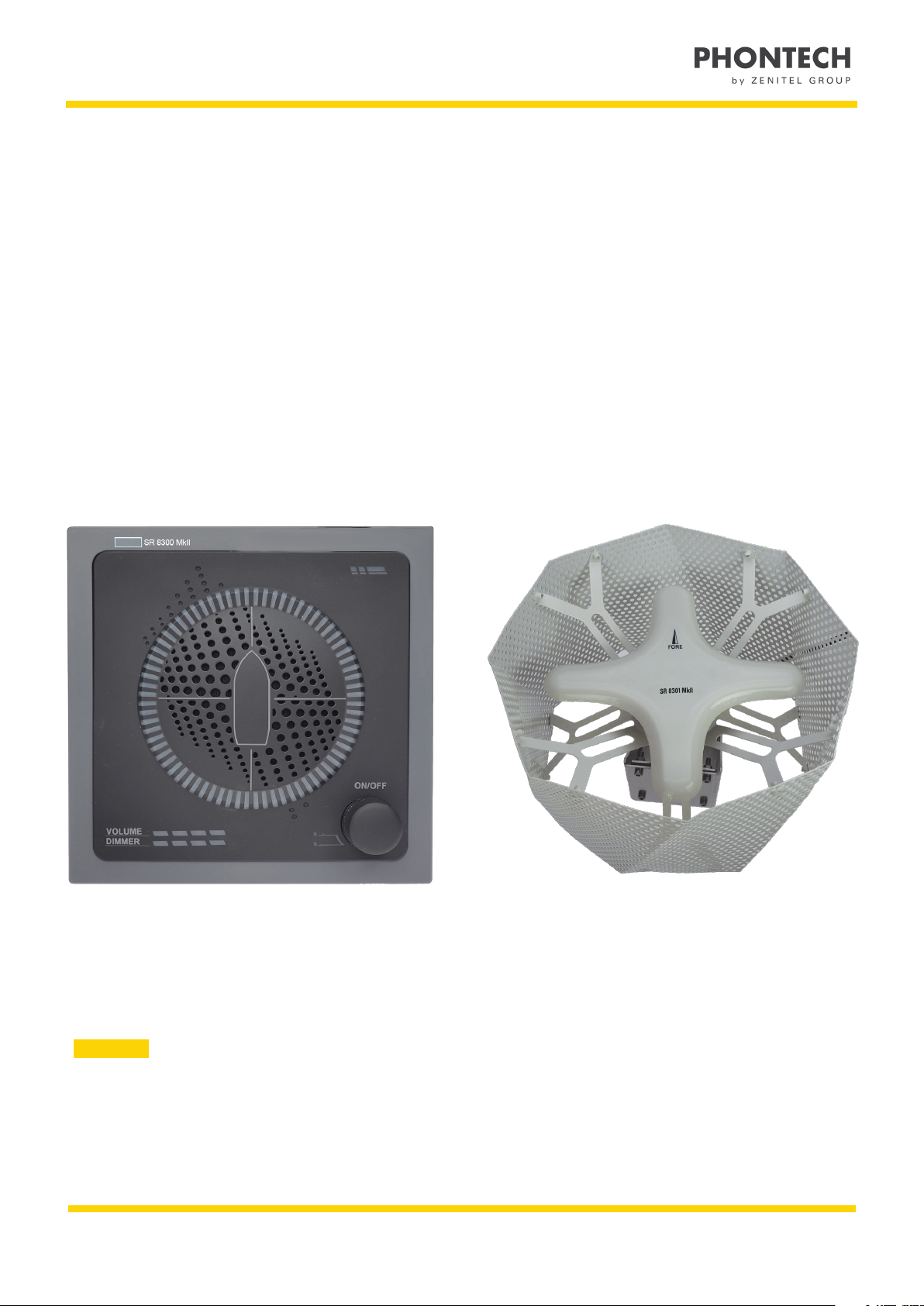
8300 MkII Sound Reception System
General
Zenitel develops and manufactures professional and state-of-the art products and communication systems for usage on land
and at sea. Zenitel supplies products and services that comply with the latest applicable standards. The use of modern test
instrumentation and detailed test procedures ensures that you are supplied with quality products.
Copies of all Phontech documentation can be downloaded from our website: www.phontech.net
All information contained within this manual has been verified and is correct. However, no responsibility is assumed by
Zenitel for inaccuracy. Zenitel reserves the right to make changes to any product(s) or module(s) described herein to improve
reliability, function or design, without further notice.
Standards
The 8300 MkII Sound Reception System has been verified, tested and meets the following product standards:
ISO 14859:2012 Ships and marine technology – Sound reception systems
IEC 60945:2002 Maritime navigation and radio communication equipment and systems – General
requirements – Methods of testing and required test results.
IEC 61162:2010-1 Maritime navigation and radio communication equipment and systems – Digital
interfaces – Part 1: Single talker and multiple listeners.
IEC 61162:2011-450 Maritime navigation and radio communication equipment and systems – Digital
interfaces-Part 450: Multiple talkers and multiple listeners – Ethernet interconnection.
IEC 62288 Edition2:2014
Maritime navigation and radio communication equipment and systems – Presentation of
navigation – related information on shipborne navigational displays – General
requirements, methods of testing and required test results.
8300 MkII also fulfils the following requirements:
SOLAS Chapter V -
Safety of navigation
- Regulation 19
Carriage requirements for shipborne navigational systems and equipment.
IMO Res. A.694(17) General requirements for shipborne radio equipment forming part of the Global Maritime
Distress and Safety System (GMDSS) and for electronic navigational aids.
IMO Res. MSC.36(63) Adoption of the international code of safety for high speed craft (1994).
IMO Res. MSC.86(70) Adoption of new and amended performance standards for navigational equipment.
IMO Res. MSC.97(73) Adoption of the international code of safety for high speed craft (2000).
IMO Res. MSC.191(79) Performance standards for the presentation of navigation-related information on the
shipborne navigational displays.
■NOTE: This product is ship wheel-marked and type approved in accordance with Marine Equipment Directive (MED).
■NOTE: All statements of conformity are available at: www.phontech.net