manuals.online logo
Brands
  1. Home
  2. •
  3. Brands
  4. •
  5. Zennio
  6. •
  7. Controllers
  8. •
  9. Zennio ZoningBOX 6 Guide

Zennio ZoningBOX 6 Guide

© Zennio Avance y Tecnología S.L. Edition 3 Further information www.zennio.com Page. 1/ 2
ZoningBOX 6
Ducted Air Zoning Actuator for up to 6 Zones
ZCL-ZB6 Technical Documentation
FEATURES
6 outputs for 12 or 24V motorised grilles*.
Zoning module allowing the control of up to 12 zones and up to
2 zone groups.
Total data saving on power failure.
Manual control through buttons and status indicator LED.
230V supply required for feeding of the 6 outputs.
KNX BCU integrated.
Size 67 x 90 x 80 mm (4.5 DIN units).
DIN rail unit assembly (EN 50022), with snap fit clamp.
CE directives compliant (CE-mark on the right side).
* Before connecting the device to the facility, it must be assured that the switch position
agree with the grilles voltage.
Programming/test button: short button press to set programming mode. If this button is held while plugging the device into the KNX bus, it goes into
safe mode.
Programming/Test LED: programming mode indicator (red). When the device goes into safe mode, it blinks (red) every half second. The manual
mode is indicated by the green color. During start up (after reset or power failure) and if the device is not in safe mode, LEDs indicator blink red once.
Figure 1. ZoningBOX 6
3
4
6*
9
7
1
5
2
5
8
GENERAL SYSTEM SPECIFICATIONS
CONCEPT
DESCRIPTION
Type of device
Electric operation control device
KNX
supply
Voltage (typical)
29VDC SELV
Voltage range
21…31VDC
Maximum
consumption
Voltage
mA
mW
29VDC (typical)
6
174
24VDC
(1)
10 240
Bus connection
Typical TP1 bus connector; 0.80mm² section
External power supply
230VAC 50/60Hz
Ambient temperature
from 0ºC to +45ºC
Storage temperature
from -20ºC to +55ºC
Ambient humidity
5 to 95% RH (no condensation)
Storage humidity (relative)
5 to 95% RH (no condensation)
Complementary characteristics
Class B
Safety class
II
Operation type
Continuous operation
Device action type
Type 1
Electrical stress period
Long
Degree of protection
IP20, clean environment
Assembly
Independent device to be mounted inside electrical panels with DIN rail (EN 50022).
Minimum clearances
Not required
KNX bus failure response
Data saving according to parameterization
Response when restarting KNX bus
Data recovering according to parameterization
Operation indication
Programming LED indicates programming mode (red) and test mode (green). Power
indicator LED (green) represents correct feeding. Each output LED indicates its status
(fixed = open grille/dumper; off = closed grilled/dumper; flashing = error, see Fig. 2)
Weight
201g
PCB CTI index
175V
Housing material
PC FR V0 halogen free
(1)
Maximum consumption in the worst case scenario (KNX Fan-In model)
1. 230V input 2. Power indicator LED 3. Grille control button 4. Grille status indicator LED
5. Grille outputs 6. 12/24V switch 7. Programming/test button 8. Programming/test LED 9. KNX connector
© Zennio Avance y Tecnología S.L. Edition 3 Further information www.zennio.com Page. 2/ 2
Attaching ZoningBOX 6 to DIN rail:
SAFETY INSTRUCTIONS
Installation should only be performed by qualified electricians following applicable regulations on preventing accidents, as
required by law
Do not connect Main Voltage (230VAC) or any other external voltages to any point of the BUS.
Connecting an external voltage might put the entire KNX system at risk.
This device contains a security short-circuit proof transformer.
Make sure during the installation that there is always sufficient insulation between the mains voltage 230VAC and the bus or
the extension inputs.
Once the device is installed, it must not be accessible from the outside.
Keep away from water and do not cover the device with clothes, paper or any other material when in use.
The WEEE logo means that this device contains electronic parts and it must be discarded properly following the instructions
of http://zennio.com/weee-regulation.
Two grilles per output
connection schematic
One grille per output
connection schematic
Removing ZoningBOX 6 from DIN rail:
OUTPUT SPECIFICATIONS AND CONNECTIONS
CONCEPT
DESCRIPTION
Number of outputs
6
Output voltage
12VDC or 24VDC (Selected meanwhile
switch)
Output type
Solid state switching device
Maximum values per
output
Quantity of grilles(2)
2
Current (RMS)
750mA
Short-circuit protection
YES
Overload protection
YES
Connection method
Cable screw terminal
Cable cross-section
0.5mm² to 2.5mm² (26-12 AWG)
(2) This value could be more restrictive depending on the current consumed by the grille.
INPUT SPECIFICATIONS AND CONNECTIONS OF EXTERNAL POWER SUPPLY
CONCEPT
DESCRIPTION
Power supply
protection fuse
Voltage
250V
Current
4A
Response type
F (Fast acting)
Connection method
Cable screw terminal
Cable cross-section
0.2mm² to 4mm² (26-10 AWG)
230V
AC
50/60Hz
Grille
Grille
Grille
Figure 2. Error notification
through grille status LED
Notes:
The simultaneous connection of a grille to several outputs nor the connection of 12VDC and 24VDC grilles at the same time
is not allowed.
In case of connecting two grilles to an output, those must have similar consumption characteristics.
The polarity of the connection must be checked.
This can be done, under the Test On mode, through the grille control
buttons: the first press should imply an attempt to open the grille, while the second press should cause an attempt to close it.
Once the device is parameterized, switched-on LEDs should correspond to open grilles.
After connecting a grille, a synchronisation must be provoked (for example, disconnecting and connecting the KNX bus).
Compatibility of grilles must be checked following the next steps for a complete verification:
1. The grille
must be connected to an enabled output, without other grilles in that output, (Please be careful to ensure the
polarity is respected).
2. The device must be fed with auxiliary power and then connected to the KNX bus.
3. The grilles connected to outputs try a sequential opening movement. If the grille needs more than 3.5 seconds to
complete the opening movement, it is not suitable for ZoningBOX.
4. Next, the grilles connected to outputs try a sequential closing movement. If the grille does not complete the closing
movement, it is not suitable for ZoningBOX.
Connection error Mx
Overload Mx
Power supply failure
LxLxL1 L2 L3 L4 L5 L6
0,5
1,0
1,5
2,0
2,5
3,0
3,5
Description:
LED On
LED Off
Lx: Grille xLED
Time (s)
Time (s)
Description:
Lx: LED output x
LED Off
LED On

Other manuals for ZoningBOX 6

2

This manual suits for next models

3

Other Zennio Controllers manuals

Zennio MAXinBOX FC 0-10V FAN Guide

Zennio

Zennio MAXinBOX FC 0-10V FAN Guide

Zennio ZoningBOX 6 User manual

Zennio

Zennio ZoningBOX 6 User manual

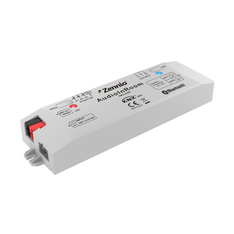
Zennio AudioInRoom ZMU-AUIR User manual

Zennio

Zennio AudioInRoom ZMU-AUIR User manual

Zennio DIMinBOX 2CH ZDI-DB2C User manual

Zennio

Zennio DIMinBOX 2CH ZDI-DB2C User manual

Zennio FANinBOX 230V 1CH Guide

Zennio

Zennio FANinBOX 230V 1CH Guide

Zennio MINiBOX 45 v3 Guide

Zennio

Zennio MINiBOX 45 v3 Guide

Zennio MAXinBOX Hospitality ZCL-HP126 User manual

Zennio

Zennio MAXinBOX Hospitality ZCL-HP126 User manual

Zennio ZIO-IB24 User manual

Zennio

Zennio ZIO-IB24 User manual

Zennio MAXinBOX 8 Plus Guide

Zennio

Zennio MAXinBOX 8 Plus Guide

Zennio FANinBOX 230V 1CH Guide

Zennio

Zennio FANinBOX 230V 1CH Guide

Zennio MAXinBOX User manual

Zennio

Zennio MAXinBOX User manual

Zennio MINiBOX 0-10V X3 User manual

Zennio

Zennio MINiBOX 0-10V X3 User manual

Zennio MAXinBOX FC 0-10V VALVE User manual

Zennio

Zennio MAXinBOX FC 0-10V VALVE User manual

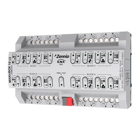
Zennio MAXinBOX 16 Guide

Zennio

Zennio MAXinBOX 16 Guide

Zennio MINiBOX 25 v3 Guide

Zennio

Zennio MINiBOX 25 v3 Guide

Zennio MAXinBOX 66 Guide

Zennio

Zennio MAXinBOX 66 Guide

Zennio MAXinBOX SHUTTER 8CH v3 Guide

Zennio

Zennio MAXinBOX SHUTTER 8CH v3 Guide

Zennio Roll-ZAS User manual

Zennio

Zennio Roll-ZAS User manual

Zennio FANinBOX 110V 1CH Guide

Zennio

Zennio FANinBOX 110V 1CH Guide

Zennio MAXinBOX66 Guide

Zennio

Zennio MAXinBOX66 Guide

Zennio LUMENTO X4 Guide

Zennio

Zennio LUMENTO X4 Guide

Zennio MINiBOX 25 Guide

Zennio

Zennio MINiBOX 25 Guide

Zennio LUMENTO X3 Guide

Zennio

Zennio LUMENTO X3 Guide

Zennio MAXinBOX SHUTTER 4CH User manual

Zennio

Zennio MAXinBOX SHUTTER 4CH User manual

Popular Controllers manuals by other brands

HEIDENHAIN ND 522 -  GUIDE Quick reference guide

HEIDENHAIN

HEIDENHAIN ND 522 - GUIDE Quick reference guide

JS Automation Corp MPC-3035 user manual

JS Automation Corp

JS Automation Corp MPC-3035 user manual

merten 7641 94 manual

merten

merten 7641 94 manual

Evco Vcolor 279 Applications manual

Evco

Evco Vcolor 279 Applications manual

JUMO dTRON 16.1 B 70.3011 operating manual

JUMO

JUMO dTRON 16.1 B 70.3011 operating manual

resideo CENTRA M6063 quick start guide

resideo

resideo CENTRA M6063 quick start guide

HHGK SCH-I user manual

HHGK

HHGK SCH-I user manual

Vaillant sensoCOMFORT VRC 720 Operating and installation instructions

Vaillant

Vaillant sensoCOMFORT VRC 720 Operating and installation instructions

IBM BladeCenter T Series installation guide

IBM

IBM BladeCenter T Series installation guide

SIGOR 9057001 quick start guide

SIGOR

SIGOR 9057001 quick start guide

PulseWorx TCM Installation guide and owner's manual

PulseWorx

PulseWorx TCM Installation guide and owner's manual

Sealey REG/MO.V2 manual

Sealey

Sealey REG/MO.V2 manual

Blaupunkt IVSC-5502 manual

Blaupunkt

Blaupunkt IVSC-5502 manual

Omron CP1E INTRODUCTION Introduction manual

Omron

Omron CP1E INTRODUCTION Introduction manual

Pressure Tech LF-540 Series Operating and service manual

Pressure Tech

Pressure Tech LF-540 Series Operating and service manual

Tormach ECM1V1.5 installation guide

Tormach

Tormach ECM1V1.5 installation guide

Simu SMC Installer manual

Simu

Simu SMC Installer manual

Pixsys DRR 245 user manual

Pixsys

Pixsys DRR 245 user manual

manuals.online logo
manuals.online logoBrands
  • About & Mission
  • Contact us
  • Privacy Policy
  • Terms and Conditions

Copyright 2025 Manuals.Online. All Rights Reserved.