manuals.online logo
Brands
  1. Home
  2. •
  3. Brands
  4. •
  5. Zennio
  6. •
  7. Controllers
  8. •
  9. Zennio MAXinBOX FC 0-10V FAN Guide

Zennio MAXinBOX FC 0-10V FAN Guide

© Zennio Avance y Tecnología S.L. Edition 8 Futher information www.zennio.com Page 1/2
MAXinBOX FC 0-10V FAN
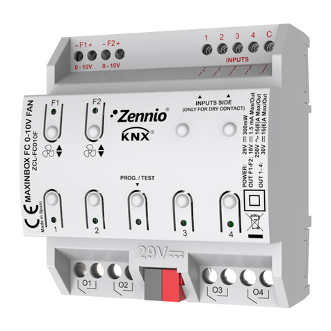
2 or 4-pipe FAN-COIL controller with 0-10VDC fan control signal
ZCL-FC010F TECHNICAL DOCUMENTATION
FEATURES
•2 x 0-10VDC individual outputs for fan control.
•4 individual outputs (suitable for capacitive loads, maximum 140µF).
•4 analog/digital inputs.
•Manual output operation in 0-10VDC and individual outputs with push
button and status LED indicator.
•10 logical functions.
•Output timing facilities.
•Total data saving on power failure.
•Integrated KNX BCU.
•Dimensions 67 x 90 x 79mm (4.5 DIN units).
•DIN rail mounting (EN 50022), through pressure.
•Possibility to connect different phases in adjoining outputs.
•Conformity with the CE directives (CE-mark on the right side).
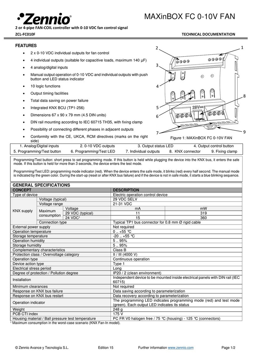
1. Analog/Digital inputs
2. 0-10VDC outputs
3. Output status LED indicator
4. Output control button
5. Programming/Test LED
6. Lower outputs
7. KNX connection
8. Programming/Test button
Figure 1: MAXinBOX FC 0-10V FAN
Programming/test button: short press to set programming mode. If this button is held while plugging the device into the KNX bus, it enters the safe
mode. If this button is held for more than 3 seconds, the device enters the test mode.
Programming/Test LED: programming mode indicator (red). When the device enters the safe mode, it blinks (red) every half second. The manual mode
is indicated by the green color. During the start-up (reset or after KNX bus failure) and if the device is not in safe mode, it starts a blue blinking sequence.
GENERAL SPECIFICATIONS
CONCEPT
DESCRIPTION
Type of device
Electric operation control device
KNX supply
Voltage (typical)
29VDC SELV
Voltage range
21..31VDC
Maximum
consumption
Voltage
mA
mW
29VDC (typical)
11
319
24VDC¹
15
360
Connection type
Typical TP1 bus connector for 0.80mm Ø rigid cable
External power supply
Not required
Operation temperature
0°C .. +55°C
Storage temperature
-20°C .. +55°C
Operation humidity
5 .. 95% (No condens.)
Storage humidity
5 .. 95% (No condens.)
Complementary characteristics
Class B
Protection class
II
Operation type
Continuous operation
Device action type
Type 1
Electrical stress period
Long
Degree of protection
IP20, clean environment
Installation
Independent device to be mounted inside electrical panels with DIN rail (EN
50022)
Minimum clearances
Not required
Response on KNX bus failure
Data saving according to parameterization
Response on KNX bus restart
Data recovery according to parameterization
Operation indicator
The programming LED indicates programming mode (red) and test mode
(green). Each output LED indicates its status
Weight
248g
PCB CTI index
175V
Housing material
PC FR V0 halogen free
¹ Maximum consumption in the worst case scenario (KNX Fan-In model)
1
7
8
3
5
6
2
4
© Zennio Avance y Tecnología S.L. Edition 8 Futher information www.zennio.com Page 2/2
SAFETY INSTRUCTIONS
•Installation should only be performed by qualified professionals according to the laws and regulations applicable in each country.
•Do not connect the mains voltage nor any other external voltage to any point of the KNX bus; it would represent a risk for the entire
KNX system. The facility must have enough insulation between the mains (or auxiliary) voltage and the KNX bus or the wires of other
accessories, in case of being installed.
•Once the device is installed (in the panel or box), it must not be accessible from outside.
•Keep the device away from water and do not cover it with clothes, paper or any other material while in use.
•The WEEE logo means that this device contains electronic parts and it must be properly disposed of by following the instructions at
http://zennio.com/weee-regulation.
OUTPUTS SPECIFICATIONS AND CONNECTIONS
CONCEPT
DESCRIPTION
Number of outputs
4
Output type
Potential-free outputs through bistable relays
with tungsten pre-contact / Micro-disconnection
Rated current per output
AC 16(6)A @ 250VAC (4000VA)
DC 7A @ 30VDC (210W)
Maximum load
per output
Resistive
4000W
Inductive
1500VA
Maximum inrush current
800A/200μs
165A/20ms
Different phases connection
Possibility of connecting different phases in
adjoining outputs
Maximum current per block
40A
Connection method
Screw terminal block
Cable cross-section
1.5-4mm² (IEC) / 26-10AWG (UL)
Outputs per common
1
Maximum response time
10ms
Mechanical lifetime (min. cycles)
3 000 000
0-10V OUPUT SPECIFICATIONS AND CONNECTIONS
CONCEPT
DESCRIPTION
Número de salidas
2
Ouput type
0..10VDC
Maximum load per output
1.5mA
Connection method
Screw terminal block
Cable cross-section
0.5-2.5mm² (IEC) / 26-12AWG (UL)
Output per common
1
INPUTS SPECIFICATIONS AND CONNECTIONS
CONCEPT
DESCRIPTION
Number of inputs
4
Inputs per common
4
Operation voltage
+3.3VDC in the common
Operation current
1mA @ 3.3VDC (per input)
Switching type
Dry voltage contacts between input and
common
Connection method
Screw terminal block
Cable cross-section
0.5-2.5mm² (IEC) / 26-12AWG (UL)
Maximum cable length
30m
NTC probe length
1.5m (up to 30m)
NTC accuracy (@ 25°C)
±0.5°C
Temperature resolution
0.1°C
Maximum response time
10ms
⚠In order to ensure the expected status of the relays,
please check thatthe device is connectedto the KNX bus
before energizing the power circuit.
WIRINGDIAGRAMS
Figure 2: (From up to down and from left to right)
Terminal block 1 and 0-10V outputs wiring examples
for two valves, two fans, one valve and one fan.
Attaching MAXinBOX FC 0-10V FAN to DIN rail:
Removing MAXinBOX FC 0-10V FAN from DIN rail:
* The micro switch number 2 in the ZN1IO-DETEC-P must be in Type B position to work properly.
INPUTSCONNECTION
Any combination of the next accessories is allowed on the inputs:
Zennio temperature
probe.
Up to two motion sensors
can be plugged into the
same device input (parallel
wiring)
Motion sensor screw
terminal.
Motion sensor references:
ZN1IO-DETEC-X
ZN1IO-DETEC-P*
Temperature Probe
Motion Sensor
Switch/Sensor/
Push button

Other manuals for MAXinBOX FC 0-10V FAN

2

This manual suits for next models

1

Other Zennio Controllers manuals

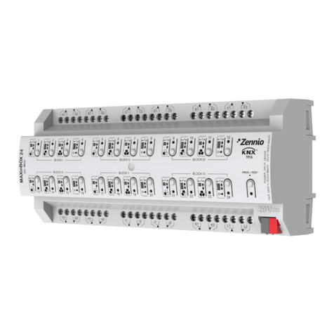
Zennio ALLinBOX 1612 v2 User manual

Zennio

Zennio ALLinBOX 1612 v2 User manual

Zennio ZCL-FC010F Guide

Zennio

Zennio ZCL-FC010F Guide

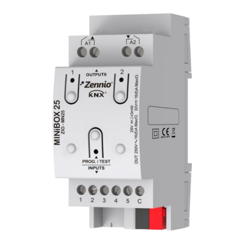
Zennio MINiBOX 20 User manual

Zennio

Zennio MINiBOX 20 User manual

Zennio FANinBOX 230V 1CH Guide

Zennio

Zennio FANinBOX 230V 1CH Guide
Zennio IRSC Plus User manual

Zennio

Zennio IRSC Plus User manual

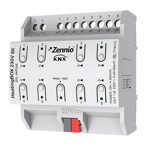
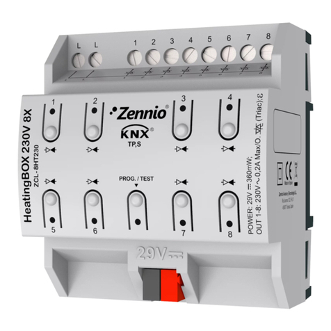
Zennio ZCL-8HT230 User manual

Zennio

Zennio ZCL-8HT230 User manual

Zennio Tecla 55 User manual

Zennio

Zennio Tecla 55 User manual

Zennio Roll-ZAS User manual

Zennio

Zennio Roll-ZAS User manual

Zennio MINiBOX 45 v3 Guide

Zennio

Zennio MINiBOX 45 v3 Guide

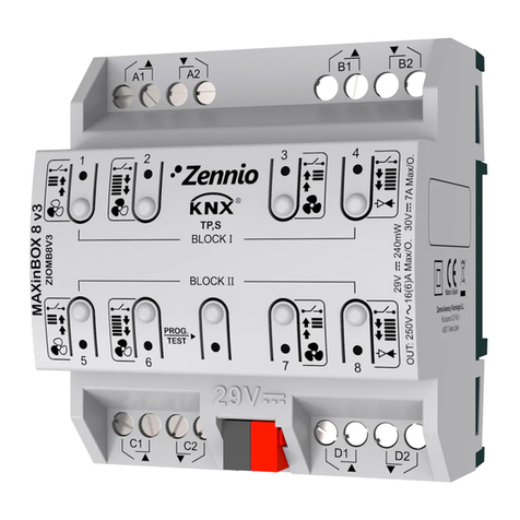
Zennio MAXinBOX 8 v3 Guide

Zennio

Zennio MAXinBOX 8 v3 Guide

Zennio FANinBOX 110V 1CH Guide

Zennio

Zennio FANinBOX 110V 1CH Guide

Zennio MAXinBOX 66 User manual

Zennio

Zennio MAXinBOX 66 User manual

Zennio MAXinBOX 8 Plus Guide

Zennio

Zennio MAXinBOX 8 Plus Guide

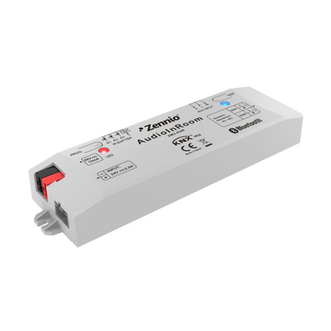
Zennio AudioInRoom User manual

Zennio

Zennio AudioInRoom User manual

Zennio HeatingBOX 230V 4X Guide

Zennio

Zennio HeatingBOX 230V 4X Guide

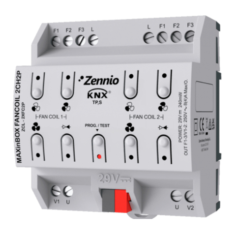
Zennio MAXinBOX FANCOIL 2CH2P User manual
Zennio

Zennio MAXinBOX FANCOIL 2CH2P User manual

Zennio ZN1DI-RGBX4 User manual

Zennio

Zennio ZN1DI-RGBX4 User manual

Zennio IDAC User manual

Zennio

Zennio IDAC User manual

Zennio MAXinBOX 16 Guide

Zennio

Zennio MAXinBOX 16 Guide

Zennio LUMENTO X3 Guide

Zennio

Zennio LUMENTO X3 Guide

Zennio inBOX 24 vT User manual

Zennio

Zennio inBOX 24 vT User manual

Zennio MINiBOX 40 v3 User manual

Zennio

Zennio MINiBOX 40 v3 User manual

Zennio MAXinBOX 24 v2 Guide

Zennio

Zennio MAXinBOX 24 v2 Guide

Zennio FANinBOX 230V 1CH Guide

Zennio

Zennio FANinBOX 230V 1CH Guide

Popular Controllers manuals by other brands

Oriental motor AR Series operating manual

Oriental motor

Oriental motor AR Series operating manual

HANYOUNG NUX BR6 instruction manual

HANYOUNG NUX

HANYOUNG NUX BR6 instruction manual

STREAM LABS Control installation guide

STREAM LABS

STREAM LABS Control installation guide

Data Video CCU-100J instruction manual

Data Video

Data Video CCU-100J instruction manual

i-MO i3N Series user manual

i-MO

i-MO i3N Series user manual

WindowMaster WMI 101 installation instructions

WindowMaster

WindowMaster WMI 101 installation instructions

Timeguard SLFM360L Installation & operating instructions

Timeguard

Timeguard SLFM360L Installation & operating instructions

ICON BIA-iPRESS user manual

ICON

ICON BIA-iPRESS user manual

FRO­NIUS SpotWelding operating instructions

FRO­NIUS

FRO­NIUS SpotWelding operating instructions

Jed Micro Pty T440 user manual

Jed Micro Pty

Jed Micro Pty T440 user manual

Black Box 3174/3274 I-Mux Series manual

Black Box

Black Box 3174/3274 I-Mux Series manual

Z-World PK2300 user manual

Z-World

Z-World PK2300 user manual

Air Lift AutoPilot V2 installation guide

Air Lift

Air Lift AutoPilot V2 installation guide

Solark O900-80V installation manual

Solark

Solark O900-80V installation manual

WorkPro Stage 2412 DMX operating instructions

WorkPro

WorkPro Stage 2412 DMX operating instructions

Smartswitch FC-006 installation manual

Smartswitch

Smartswitch FC-006 installation manual

Linortek Netbell-NTG Setting instructions

Linortek

Linortek Netbell-NTG Setting instructions

Oriental motor BXII Series operating manual

Oriental motor

Oriental motor BXII Series operating manual

manuals.online logo
manuals.online logoBrands
  • About & Mission
  • Contact us
  • Privacy Policy
  • Terms and Conditions

Copyright 2025 Manuals.Online. All Rights Reserved.