Zepro ZHZ 500 User manual

ZEPRO
Tel.: +46 (0)10-459 05 00
73161TL
2022-11-30
Installation Instruction
Tail Lift
ZHZ 500/600-850


Contents
3www.zepro.com
Contents
1 Important information ..................................................................................... 5
1.1 Attention! ................................................................................................ 5
1.2 Technical support.................................................................................... 5
1.7 Identication ........................................................................................... 6
1.3 CE marking............................................................................................. 6
1.4 Product approval ................................................................................... 6
1.5 Hydraulic oil ............................................................................................ 6
1.6 Guarantee............................................................................................... 6
1.8 Repainting .............................................................................................. 7
1.9 Battery maintenance............................................................................... 7
2 Safety rules ....................................................................................................... 8
2.1 Moving parts - free movement................................................................ 8
2.2 Connection of third-party equipment is forbidden................................... 8
2.3 Installation .............................................................................................. 8
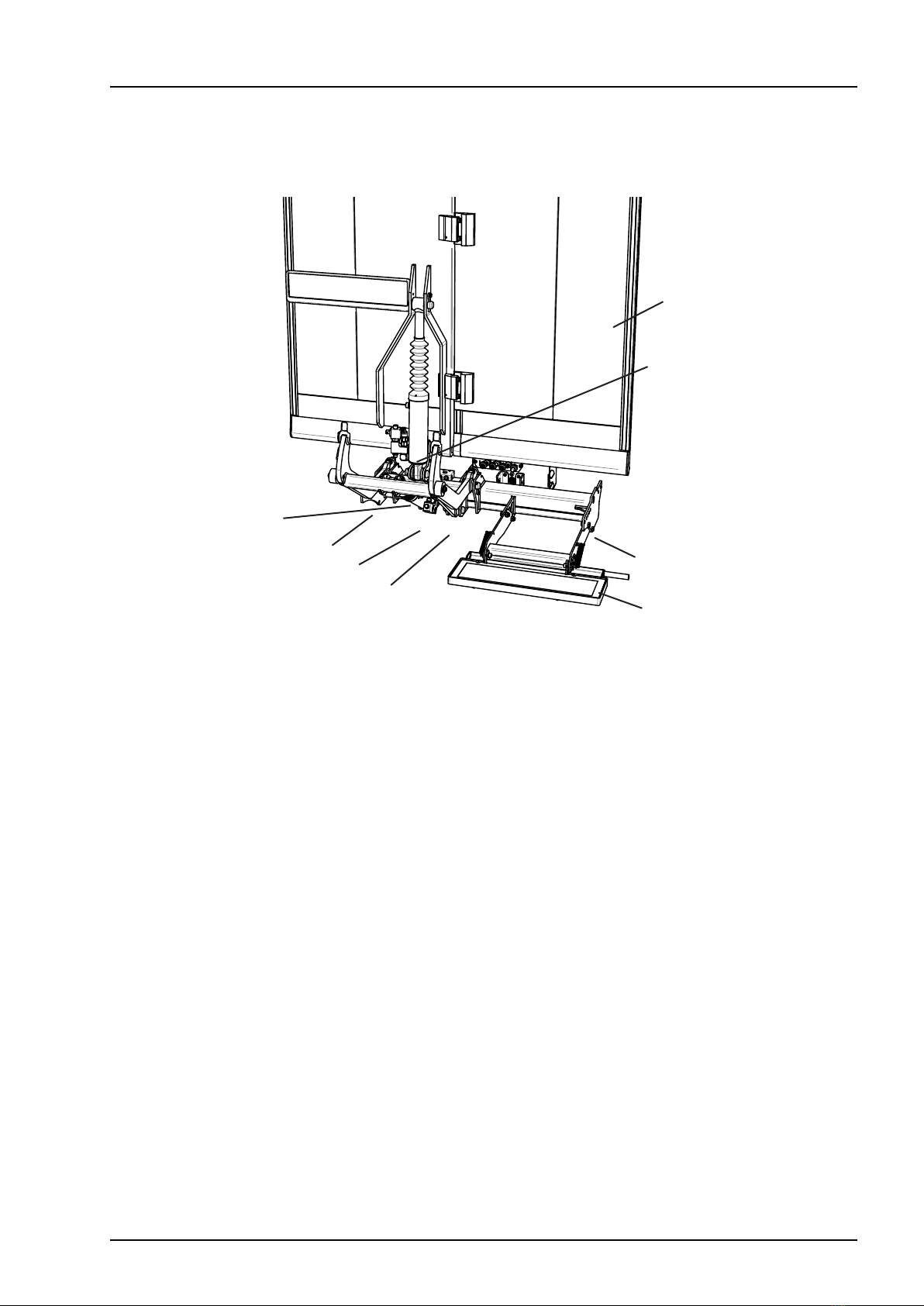
3 Main parts ......................................................................................................... 9
4 Before installation .......................................................................................... 10
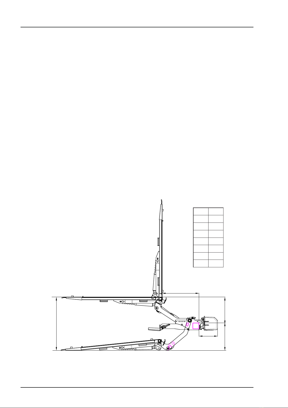
4.1 Calculating the installed dimensions ................................................... 10
4.2 Temporary connection .......................................................................... 11
5 Installation ...................................................................................................... 13
5.1 Installing
the lift............................................................................ 13
5.2 Installing the Platform ........................................................................... 14
5.3 Installing the angle sensor.................................................................... 15
5.4 Installing the hydraulic unit ................................................................... 16
5.5 Control devices..................................................................................... 17
6 Cable routing ................................................................................................. 18
6.1 General................................................................................................. 18
6.2 Sizing electrical systems ...................................................................... 19
6.3 Main power cable, earth cable, main fuse and main switch ................. 21
6.4 Installation of license plate light............................................................ 22
6.5 Installation of connection ramp............................................................. 23
6.6 Armstops .............................................................................................. 23
6.7 Platform stop ....................................................................................... 23
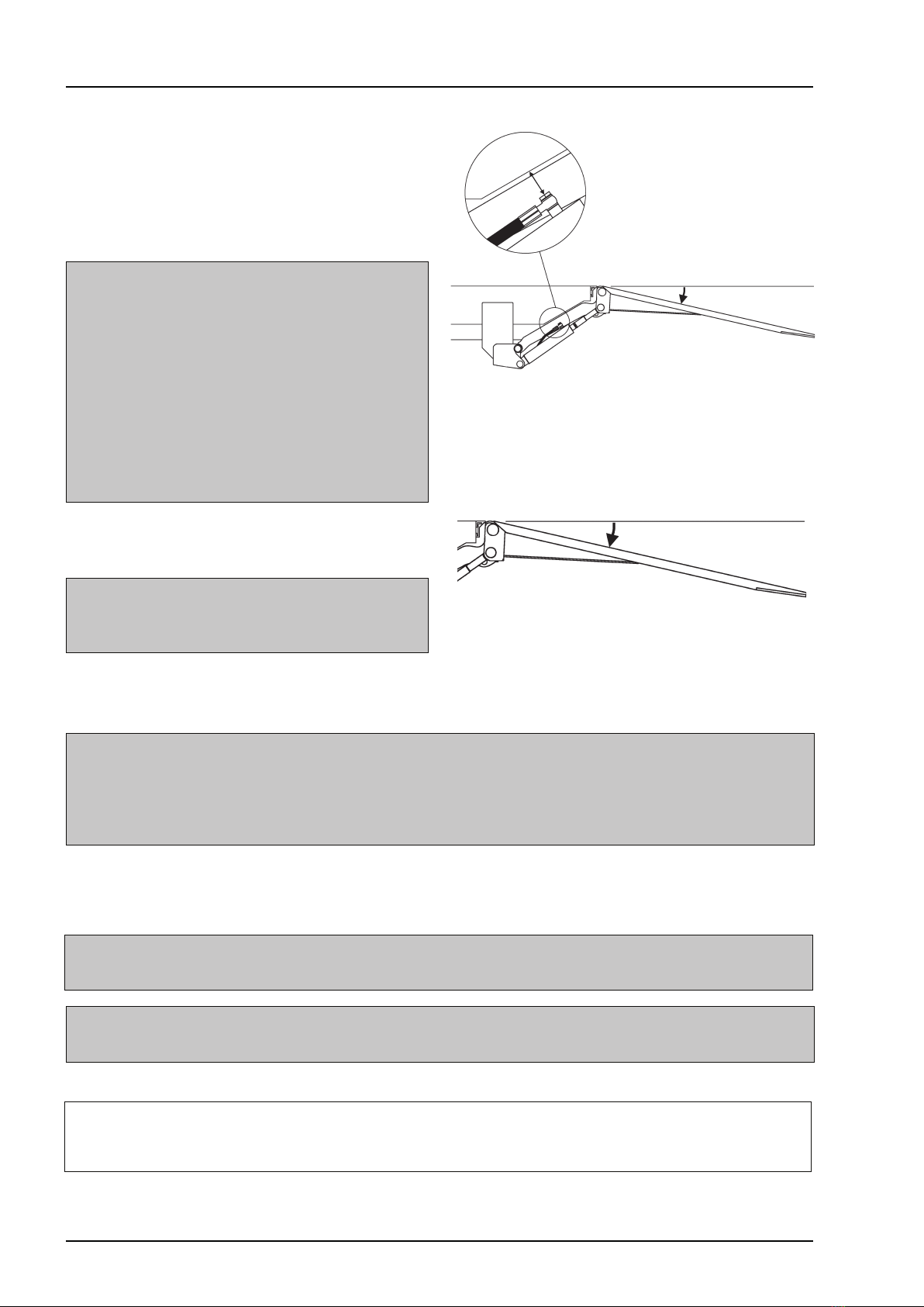
6.8 Adjustment of tilt cylinder...................................................................... 24
6.9 Purging the cylinders ............................................................................ 25

4
Contents
www.zepro.com
7 Electrical
and
hydraulic drawings................................................................. 26
7.1 ZHZ-500/600-850 MA........................................................................... 26
7.2 Cab switch and open platform alarm .................................................... 27
7.3 Foot controlers and warning lights........................................................ 28
8 Lubrication and fluid level check.................................................................. 29
8.1 Lubrication ............................................................................................ 29
8.2 Fluid level check ................................................................................... 29
9 Markings and decals ...................................................................................... 30
9.1 Load diagram........................................................................................ 31
9.8 Work area ............................................................................................ 32
9.3 Driver’s instructions .............................................................................. 32
9.2 Identicationplate............................................................................... 32
9.4 Danger area ......................................................................................... 33
9.5 Warning tape ....................................................................................... 33
9.6 Warningags....................................................................................... 33
9.7 CE marking........................................................................................... 33
10 Testing and verification ................................................................................. 34
10.1 Static test loading ................................................................................. 34
10.2 Dynamic test loading. ........................................................................... 35
10.3 Testing safety functions ........................................................................ 35
11 Specifications ................................................................................................ 36
11.1 Weights ................................................................................................ 36
11.2 Load centre........................................................................................... 37
12 Registration .................................................................................................... 38

Important information
5www.zepro.com
ZHZ 500/600-850
1 Important information
1.1 Attention!
The following warning signs appear in the installation instructions and are intended to draw your attention to cir-
cumstances that can potentially cause problems, near misses, personal injury and/or damage to the product, etc.
mWARNING!
WARNING
indicates a potential hazard, which if ignored may lead to serious, life-threatening injury.
mCAUTION!
CAUTION
indicates a potential hazard, which if ignored, may lead to minor injuries.
IMPORTANT!
IMPORTANT indicates a risk of equipment damage.
NOTE!
NOTE! refers to additional information that may help the reader understand, or perform, a given operation.
1.2 Technical support
If technical support is needed, please contact ZEPRO. Tel: +46 (0)10-459 05 04, E-mail: [email protected].
Always be ready to state the tail lift’s production number to guarantee you receive the correct information.
Theproductionnumberisgivenontheidenticationplatelocatedonthetailliftframe.
Fig 1. Identification plate

6
Important information
www.zepro.com
ZHZ 500/600-850
1.3 CE marking
ZEPRO tail lifts for sale on the European market are CE marked (Conformité Européenne). The manufacturer
guarantees that the product complies with the EU Machinery Directive.
Followtheinstallationinstructionscarefully.Modicationsnotapprovedinwritingbythemanufacturerarenot
permitted. Welding is not permitted.
1.4 Product approval
Properly assembled, this product meets relevant requirements according to EN 1756-1:2001 + A1:2008.
1.5 Hydraulic oil
If the hydraulic oil needs to be replenished, only the oil recommended by ZEPRO is permitted to be used.
Hydraulicsystemswithhydraulicoiltankswithoutlabellingareonlypermittedtobelledwithhighlyrened
mineral oil (art. no. 21963, 1 litre).
Hydraulicsystemswithhydraulicoiltanksmarkedwithaspecicationforthehydraulicoilareonlypermittedto
belledwiththeoilspeciedonthelabel.
1.6 Guarantee
Afterinstallation,testingandverication,thetaillift’sdeliverycardmustberegisteredfortheguaranteetobevalid.
1.7 Identication
Max. lifting capacity x 1 (kg)
Max. lifting height -850 = 850 mm
Cylinder model, MA = Double-acting adjustable tilt
Single-acting lift
Identication list E.g. - 600 - 850 MA
_ _ _ - _ _ _ - _ _ _ _ _

Important information
7www.zepro.com
ZHZ 500/600-850
1.8 Repainting
Fig 2. Piston rods, cylin-
der covers and boots
Fig 3. Hydraulic hoses Fig 4. Cables
1.9 Battery maintenance
When storing for longer than 1 week, it is recommended to disconnect the lift from the battery via the main
switch or by releasing the lift’s main fuse, in order to reduce the risk of the battery discharging. The length of
time the vehicle can be stored without the battery charge level becoming too low depends on the condition of
the battery, the charge level prior to storage and how much power other components in the vehicle take from
the battery. After a period of storage, the battery must always be charged fully before operating the lift.
When the lift is operated repeatedly without
starting or using the vehicle during lift installation or carrying out
service and repairs, use the battery charger between operations to maintain battery charge
.
IMPORTANT!
The battery charger must be disconnected when operating the lift. Risk of material damage.
IMPORTANT!
Piston rods and cylinder covers must not be painted. Among other things, this can damage the cylinder gaskets.
Boots, hydraulic hoses and cables may not be coated/painted as the solvent in the paint can damage the hoses and cables and
impair durability.

8
Safety rules
www.zepro.com
ZHZ 500/600-850
2 Safety rules
2.1 Moving parts - free movement
mWARNING!
Duringnalinspection*,thespaceoccupiedbythe
moving cylinders must be cleared and made safe.
There is a risk of collision between the cylinder and
the following items: subframe, truck chassis, beam
for rear light (number plate) and the chassis bracket
of the lift (with a short overhang).
**Finalinspectiontobecarriedoutwiththeplatform
atthevehicleoorandtilteddown10°.Theclear-
ance from the closest part of the cylinder must be
at least 40 mm.
mWARNING!
The platform may not be tilted down more than
10º from the horizontal.
10º
10º
Fig 5. Clearance to the closest part of
the cylinder must be at least 40 mm
Fig 6. The platform may not be tilted down
more than 10º from the horizontal
2.2 Connection of third-party equipment is forbidden
mWARNING!
Connecting third-party equipment (electric or hydraulic) to Zepro tail lifts is forbidden. Connecting third-party
equipment could interfere with the lift’s system and its safety functions. Risk of injury and damage. If it is
necessary to install other equipment, check the vehicle manufacturer’s body instructions and use the at-
tachment features on the vehicle.
2.3 Installation
mWARNING!
Installation where the platform cannot reach ground level is prohibited.
mWARNING!
ZEPRO tail lifts are only approved for installation using ZEPRO assembly kits.
IMPORTANT!
Allspeciedtighteningtorquesapplywhenusingtorquewrenchorscrew/nutrunnerwithtorquecontrol.
Torque spread max ±5%.

Main parts
9www.zepro.com
ZHZ 500/600-850
3 Main parts
Platform
Tilt cylinder
Lift arm
Support arm
Frame
Lift cylinder
Link
Step
Fig 7. Overview

10
Before installation
www.zepro.com
ZHZ 500/600-850
4 Before installation
4.1 Calculating the installed dimensions
For easier installation, it is useful to calculate and specify the necessary dimensions in advance. Determine
theC-dimensionrst,thenobtaintheotherdimensionsfromtherelevanttable.Youshouldtrytopositionthe
liftashighaspossiblewithinthespeciedC-dimensioninthetable.
4.1.1 C-dimension
TheC-dimensionisthedistancebetweenthetopthesupportframeandthevehicleoorlevel.Thisdimension
governs how far the lift needs to be installed under the vehicle body (D-dimension) and the space between the
liftarmsintheupperpositionandthevehicleoorlevel(A-dimension).
4.1.2 D-dimension
The D-dimension is the space that the lift needs, measured from the rear edge of the body to the front edge of
the support frame (in the direction of the vehicle). Once the C-dimension has been determined, the D-dimension
can be obtained from the table.
4.1.3 H-dimension
TheH-dimensionistheheightfromground(unloaded)tothevehicleoorlevel.TheH-dimensionmustnot
be greater than the lift’s maximum lifting height. The lift’s platform must always be able to reach ground level.
H = B+C
B max. 400
297
C
D
C D
450 557
400 597
350 629
300 640
250 674
200 688
150 698
ZHZ 500/600-850

Before installation
11www.zepro.com
ZHZ 500/600-850
4.2 Temporary connection
When the tail lift is installed, it is sometimes necessary to operate its functions in order to change the position
of the cylinders and the lift arms. Temporarily connect the lift to enable the lift functions.
1. Connect a suitable control device to C1, see section 4.2.2.
2. Connect the tail lift’s main power cable to battery +12/24V.
3. Connect the negative battery terminal to the tail lift’s earth cable (GND).
4. Relay card TLC-B1: When operating,
connect
a cable (jumper) between an available power supply con-
nection (+) and CS on the relay card to simulate switch CS being on. Remove the cable immediately after
completed operation.
mWARNING!
Take great care while running the lift functions and make sure nothing gets pinched: risk of personal injury and material damage.
Fig 8. Temporary connection
4.2.1 Battery maintenance
When installing the lift, when the lift is operated repeatedly,
the battery charger must be used between opera-
tions to maintain the battery charge level
.
TLC-B1
WL1 U7 U6 U5 U5 U4 U4 U3 U2 U1 U0
++
WL2
PA+
S5
S1+
S4
S3
S2
S1
S5+
S4+
S3+
S2+
PA-
CS+
Down
2H
Out
Down
Down
C1+
C1+
Up
Tilt
In
C2+
Up
Tilt
C3+
Up
CS
+
U1
U2
U3
U0 +
Jumper
C1
IMPORTANT!
The battery charger must not be connected when operating the lift. Risk of material damage.

12
Before installation
www.zepro.com
ZHZ 500/600-850
WL1 U7 U6 U5 U5 U4 U4 U3 U2 U1 U0
++
U0 +
+
U1
U2
U3
WL2
PA+
S5
S1+
S4
S3
S2
S1
S5+
S4+
S3+
S2+
PA-
CS
CS+
Down
2H
Out
Down
Down
C1+
C1+
Up
Tilt
In
C2+
Up
Tilt
C3+
Up
Ctrl 3
Ctrl 2
Ctrl 1
CD9
Up
Tilt
Down
CD10
Up
Down
Up
Tilt
Down
2H
CD1
123
4
CD11
4.2.2 Connecting the control device to the TLC-B1 relay card
The connection of warning lights and the most commonly occurring controller (CD (Control Device)) models
isshownbelow.Possiblecontrollermodelsvarydependingonliftmodel,congurationandrelevantmarket.
mWARNING!
Make sure the control relay is disconnected from power before connecting. Connecting more than one controller to each
connection is not permitted. Risk of material damage.
Black C1+
White ( )
Brown Up
Yellow Down
Blue Tilt
Black C1+
Blue 2H
Black C2+
White ( )
Brown Up
Yellow Down
Grey Not used
Black C2+
White ( )
Brown Up
Yellow Down
Blue Tilt
Black C3+
White ( )
Brown Up
Yellow Down

Installation
13www.zepro.com
ZHZ 500/600-850
5 Installation
5.1 Installing
the lift
1. Mount the lift to the chassibracket without tightening the screws. The number of screws and theír placement
depends on the type of bracket used, see installation instruction for the mounting kit in question.
2. Usetheadjustingscrewsforadjustingthearmstoptomaketheheightdierencebetweenthecenteron
theliftarmsshaftholeandthewehiclesbodyoortoapprox.1inch,seeFig 9.
3. Then adjust the lift as close as possible to the backdoors, taking into account the platform.
NOTE!
Foldable platform requires more space.
4. Tighten the mounting screws using a torque wrench. Tightening torque 80 Nm.
Fig 9. Use the adjusting screws for adjusting the armstop
Arm stop adjusting screw
25 mm
Front hole pattern
Rear hole pattern
Art. no. Front hole pattern Rear hole pattern
72807TL 2 screws M12x35 mm 3 screws M12x35 mm
76013TL 2 screws M12x35 mm 3 screws M12x35 mm
73029TL 2 screws M12x35 mm 3 screws M12x35 mm
74914TL 2 screws M12x35 mm 2 screws M12x35 mm
75018TL 2 screws M12x35 mm 2 screws M12x35 mm
73169TL 2 screws M12x35 mm 3 screws M12x35 mm
73167TL 2 screws M12x35 mm 3 screws M12x35 mm
74451TL 2 screws M12x35 mm 2 screws M12x35 mm
74452TL 2 screws M12x35 mm 3 screws M12x35 mm
75236TL 2 screws M12x35 mm 3 screws M12x35 mm

14
Installation
www.zepro.com
ZHZ 500/600-850
5.2 Installing the Platform
1. Remove the cover at the lower en of the platform, see Fig 10.
2. Pushtheshaftoutotheplatform,seeFig 11.
3. Position the platform on the lift arms, see Fig 12.
4. Pushtheshaftinwardsuntilitsushwiththeplatformssufaceontheoppositeside,
see Fig 13:1.
5. Fit in the screw (attached), see Fig 13:2, to lock the platform shaft.
6. Retthecover.
7. Attach the cylinder to the cylinder bracket and lock with locking pin, see Fig 14.
Fig 10. Remove the cover
Fig 11. Push the shaft out off the platform Fig 12. Place the platform
Fig 13. Fit in and lock the platform shaft
1
2
Fig 14. Attach and lock the cylinder

Installation
15www.zepro.com
ZHZ 500/600-850
5.3 Installing the angle sensor
If the lift is equipped with radio control, associated
angle sensor must be mounted on the platform,
see Fig 15. Use sensor bracket, art. no. 53937TL
(Ordered separately).
1. Mark the position of the bracket holes on the plat-
form and drill suitable holes.
2. Mount the bracket (Art. no. 53937TL) using the
attached two pop rivets, see Fig 15.
3. Mount the angle sensor with the connection cable
pointing upvards and out on the bracket using the
attached screws, see Fig 16.
4. Mount the cable among existing cables using cable
ties. Connection is described later in section 7.
NOTE!
The cable must be installed suciently far from or be
protected against sharp edges, so that it cannot chafe
or otherwise sustain damage that can lead to a short
circuit or cable re.
In general, care must be taken whenever routing
cables, in order to ensure a longer cable service life
and to reduce the risk of unnecessary operational
stoppages.
Fig 15. Mounting of bracket and angle sensor
Fig 16. Mounted angle sensor

16
Installation
www.zepro.com
ZHZ 500/600-850
5.4 Installing the hydraulic unit
A suitable location for the hydraulic unit is on the
wheel housing. The unit is ideally secured with the
supplied bracket.
The hydraulic unit can be installed horizontally or
vertically.
NOTE!
Replace transport plug with regular tank cap before
removing plugs in A and B.
5.4.1 Connection of hydraulic hoses to
hydraulic unit
Return side tilt cylinder (A), Pressure side lift/tilt
cylinder (B).
Fig 17. Return side tilt cylinder (A),
Pressure side lift/tilt cylinder (B).
5.5 Installation of license plate light
Connect the license plate light to the vehicles ordinary lights cabeling.
Follow the manufacturer’s recommendations.
Fig 18. Example of connecting the license plate light
Vehicle lighting License plate light
(+)12V
GND
2A

Installation
17www.zepro.com
ZHZ 500/600-850
Connection ramp
5.6 Installation of connection ramp
Install the connection ramp to that it connects 40-60
mm in on the platform.
A safety distance of 75 mm is recommended when
theplatformislevelwiththevehicleoor.
5.7 Armstops
The armstops must be adjusted after installation of the
installation kit and lift.
Adjust with the adjustment screws, so that both arm-
stops contact the lift arms at the same time.
NOTE!
On some vehicle models, the space can be so
conned that the lift has to be lowered in order for the
adjusting screws to be accessible. If so, measure the
need for adjustment rst.
5.8 Platform stop
(Applies only to folding platform)
When the lift platform is folded up and closed against
the vehicle body, the platform stop must automatically
lock the various parts of the platform against each other.
Fig 19. Connection ramp
Fig 20. Armstops
Fig 21. Platform stop

18
Installation
www.zepro.com
ZHZ 500/600-850
5.9 Adjustment of tilt cylinder
+
30 mm
1. Undo the locking nut.
2. Turn the piston rod clockwise to angle down the
platform or anti-clockwise to angle up the plat-
form. Lock the lug in place using a suitable tool.
Adjust the tilt cylinder in horizontal position.
NOTE!
The maximum permitted adjusting distance is
30 mm.
3. After adjusting, tighten the locking nut.
Tightening torque 80 Nm
Fig 22. The tilt cylinder can be adjusted
so that the lift platform stops in the verti-
cal position behind the rear doors.
Fig 23. Undo the locking nut.
Fig 24. Turn the piston rod clockwise to
angle down the platform or anti-clock-
wise to angle up the platform.
Fig 25. The maximum permitted ad-
justing distance is 30 mm
mWARNING!
Take great care during test operation before
adjusting the tilt cylinder to ensure that the vehicle
body is not damaged.
Make sure that the tilt cylinder is adjusted in such a
way that the platform does not catch on the vehicle
body when the platform is tilted up fully.

Installation
19www.zepro.com
ZHZ 500/600-850
5.10 Purging the cylinders
Purge the lift cylinders by lowering the platform all the way to the ground a few times. It may be necessary to
raise the truck to allow the platform to be lowered completely.
Purge the tilt cylinders by tilting the platform all the way up to the vehicle body and then all the way down.

20
Installation
www.zepro.com
ZHZ 500/600-850
5.11 Control devices
1. Fit the controllers in the desired locations. How-
ever, locate them such that the operator’s work-
ing position is as
safe as possible, and with an
adequate overview of the load, tail lift and their
working area.
2. The distance between the vehicle’s rear edge and
the centre of the controllers must be 300-600 mm.
The distance between the controllers must be at
least 260 mm. See Fig 26.
3. Any additional controllers can be installed in an
optional location.
4. Run the controller cabling to the tail lift cable grommet.
Connection is described later in section 7.
Fig 26. Installing control devices for two-handed grip
Min. 260 mm.
300 - 600 mm.
Fig 27. Installing control device
mWARNING!
Acontrollermustalwaysbettedonthesidethatisfacingawayfromtracinmotion.Ifthereisaneedfora
controllerontheoppositeside,afurthercontrollermustthereforebetted.Fittingontheothersideinvolves
increased risk of injury
.
This manual suits for next models
2
Table of contents
Other Zepro Lifting System manuals

Zepro
Zepro 78826TL User manual

Zepro
Zepro ZN 2500-130 User manual

Zepro
Zepro Z3N 75-100 User manual

Zepro
Zepro ZS MK2 User manual

Zepro
Zepro ZDK 250 135 User manual

Zepro
Zepro ZHD 1500 Original operating manual

Zepro
Zepro Z 10 User manual

Zepro
Zepro ZHD-1500-MA-DA User manual

Zepro
Zepro ZAHD 150/200 User manual

Zepro
Zepro Z 2500-130 Series User manual