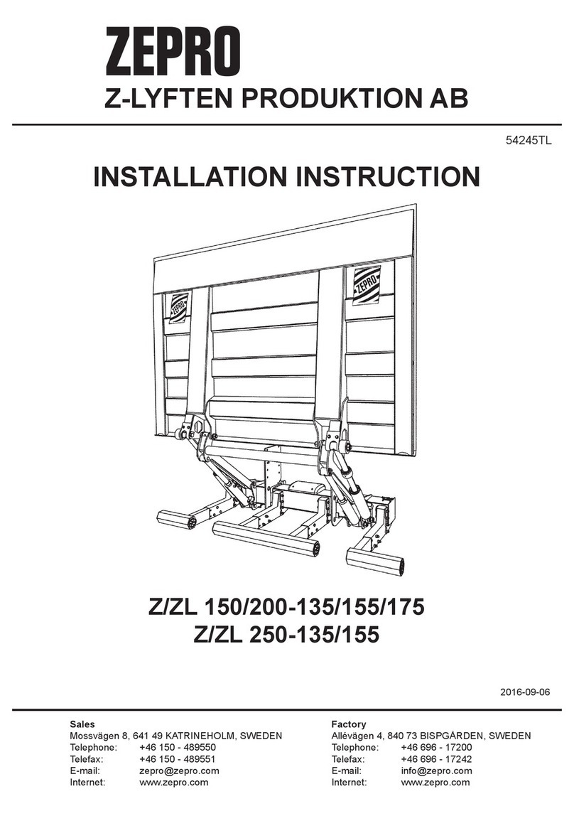
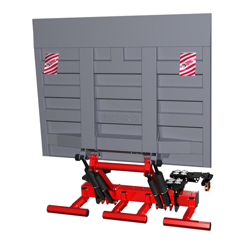
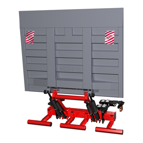
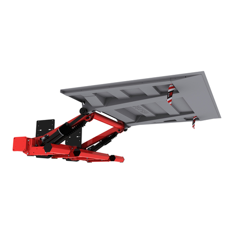
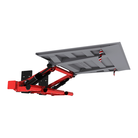
Zepro ZS MK2 User manual

ZEPRO
Tel.: +46 (0)10-459 05 00
78612TL
Installation instructions
Tail Lift
ZS MK2
2021-06-16


ZS MK2Contents
3
www.zepro.com
Contents
1 Important information ...............................................................................5
1.1 Attention! ...........................................................................................5
1.2 Conguration .....................................................................................5
1.3 Technicalsupport ..............................................................................5
1.4 CEmarking........................................................................................6
1.5 Productapproval ..............................................................................6
1.6 Hydraulicoil.......................................................................................6
1.7 Guarantee .........................................................................................6
1.8 Repainting .........................................................................................7
1.9 Battery maintenance .........................................................................7
2 Safety rules .................................................................................................8
2.1 Movingparts-freemovement...........................................................8
2.2 Connectionofthird-partyequipmentisforbidden..............................8
2.3 Installation .........................................................................................8
3 Before installation .....................................................................................9
3.1 Underrunprotection...........................................................................9
3.2 Calculatingtheinstallationdimensions(Standardlift)..................... 11
3.3 Calculatingtheinstallationdimensions(Slimeline) .........................13
4 Rear member cut-outs..............................................................................15
4.1 Preparethetaillift ...........................................................................16
4.2 Temporaryconnectionoflift ............................................................18
4.3 Adjustmentofslideproles .............................................................19
5 Installation.................................................................................................20
5.1 Supportframe..................................................................................20
5.2 Settingtheworkposition .................................................................22
5.3 Work position lock (Option) .............................................................23
5.4 Platform ...........................................................................................24
5.7 Platformstop ...................................................................................26
5.5 Arm stops ........................................................................................26
5.6 Purgingthecylinders.......................................................................26
5.8 Transport stops................................................................................27
5.9 Anglesensorforautotilt...................................................................29
5.10 Controldevice .................................................................................30
6 Running / connecting cabling ................................................................32
6.1 Maximumpowerconsumption-Minimumrecommended
conductorcross-sectionalarea .......................................................32
6.2 General............................................................................................33
6.3 Mainpowercable,groundcableandmainfuse..............................33
6.4 Controlpowercable ........................................................................34
6.5 Openplatformalarm........................................................................34
ZS MK2
4
Contents
www.zepro.com
7 Connection of controller and warning lights .........................................35
7.1 Cablegrommet................................................................................35
7.2 Footcontroller/Warninglights........................................................36
7.3 Connection ......................................................................................37
8 Powering up the tail lift ............................................................................39
9 Electrical and hydraulic diagrams ..........................................................40
9.1 ZS MK2 ...........................................................................................40
9.2 ZSMK2Autotilt................................................................................41
10 Lubrication and oil level check ...............................................................42
10.1 Lubricationpoints ............................................................................42
10.2 Oillevelcheck .................................................................................42
11 Marking......................................................................................................43
11.1 Max permissible load.......................................................................44
11.2 Identicationplate ..........................................................................45
11.3 Work area .......................................................................................45
11.4 Warningtape ..................................................................................45
11.5 Controldevicesticker ......................................................................46
11.6 Dangerarea ...................................................................................47
11.7 Warningags..................................................................................47
12 Testing and verification............................................................................48
12.1 Static load test.................................................................................48
12.2 Dynamic load test............................................................................49
12.3 Testofsafetyfunctions....................................................................49
13 Registration...............................................................................................50
14 Specifications ..........................................................................................50
14.1 Weights ..........................................................................................50

ZS MK2Importantinformation
5
www.zepro.com
1 Important information
1.1 Attention!
The following warning signs appear in the installation instructions and are intended to draw your attention to
circumstances that can potentially cause problems, near misses, personal injury and/or damage to the product,
etc.
m WARNING!
WARNING
indicatesapotentialhazard,whichifignoredmayleadtoserious,life-threateninginjury.
m CAUTION!
CAUTION
indicatesapotentialhazard,whichifignored,mayleadtominorinjuries.
IMPORTANT!
IMPORTANTindicatesariskofequipmentdamage.
NOTE!
NOTE! refers to additional information that may help the reader understand, or perform, a given operation.
1.2 Conguration
This tail lift is available in a many different congurations. It is available in two versions, Standard and Slimline.
Lift height, lift capacity, slider prole length and platform size may vary. However, the installation principles are
the same whatever the conguration.
• Standard or Slimline
• Lifting capacity: 1500, 2000 or 2500 Kg.
• Max lift height: -135 (1356 mm), -155 (1542 mm), -175 (1727 mm).
• Slide proles: 1590, 1700 and 1850 mm.
• Platform: 1565 x 2400, 1765 x 2400, or 1965 x 2400 mm.
1.3 Technical support
If technical support is needed, please contact ZEPRO. Tel: +46 (0)10-459 05 04, E-mail: z[email protected].
Always be ready to state the tail lift’s production number to guarantee you receive the correct information. The
production number is given on the identication plate located on the tail lift frame.
Picture 1. Identication plate

ZS MK2
6
Importantinformation
www.zepro.com
1.4 CE marking
ZEPRO tail lifts for sale on the European market are CE marked (Conformité Européenne). The manufacturer
guarantees that the product complies with the EU Machinery Directive.
Follow the installation instructions carefully. Modications not approved in writing by the manufacturer are
not permitted. Welding is not permitted.
1.5 Product approval
Properly assembled, this product meets relevant requirements according to EN 1756-1:2001 + A1:2008.
1.6 Hydraulic oil
If the hydraulic oil needs to be replenished, only the oil recommended by ZEPRO is permitted to be used.
Hydraulic systems with hydraulic oil tanks without labelling are only permitted to be lled with highly rened
mineral oil (art. no. 21963, 1 litre).
Hydraulic systems with hydraulic oil tanks marked with a specication for the hydraulic oil are only permitted
to be lled with the oil specied on the label.
1.7 Guarantee
After installation, testing and verication, the tail lift’s delivery card must be registered for the guarantee to be valid.

ZS MK2Importantinformation
7
www.zepro.com
1.8 Repainting
IMPORTANT!
Pistonrodsandcylindercoversmustnotbepainted.Amongotherthings,thiscandamagethecylindergaskets.
Boots,hydraulichosesandcablesmaynotbecoated/paintedasthesolventinthepaintcandamagethehosesandcablesand
impairdurability.
Picture 2. Piston rods, cyl-
inder covers and boots
Picture 3. Hydraulic hoses Picture 4. Cables
1.9 Battery maintenance
When storing for longer than 1 week, it is recommended to disconnect the lift from the battery via the main
switch or by releasing the lift’s main fuse, in order to reduce the risk of the battery discharging. The length of
time the vehicle can be stored without the battery charge level becoming too low depends on the condition of
the battery, the charge level prior to storage and how much power other components in the vehicle take from
the battery. After a period of storage, the battery must always be charged fully before operating the lift.
When the lift is operated repeatedly without
starting or using the vehicle during lift installation or carrying out
service and repairs, use the battery charger between operations to maintain battery charge
.
IMPORTANT!
Thebatterychargermustbedisconnectedwhenoperatingthelift.Riskofmaterialdamage.

ZS MK2
8
Safetyrules
www.zepro.com
2 Safety rules
2.1 Moving parts - free movement
m WARNING!
During nal inspection*, the space occupied by the
moving cylinders must be cleared and made safe.
There is a risk of collision between the cylinder and
the following items: subframe, truck chassis, beam
for rear light (number plate) and the chassis bracket
of the lift (with a short overhang).
**Final inspection to be carried out with the platform
at the vehicle oor and tilted down 10°. The clear-
ance from the closest part of the cylinder must be
at least 40 mm.
m WARNING!
The platform may not be tilted down more than
10º from the horizontal.
min. 40 mm
10º
10º
Picture 5. Clearance to the closest part of
the cylinder must be at least 40 mm
Picture 6. The platform may not be tilted
down more than 10º from the horizontal
2.2 Connection of third-party equipment is forbidden
m WARNING!
Connecting third-party equipment (electric or hydraulic) to Zepro tail lifts is forbidden. Connecting third-
party equipment could interfere with the lift’s system and its safety functions. Risk of injury and damage. If
it is necessary to install other equipment, check the vehicle manufacturer’s body instructions and use the
attachment features on the vehicle.
2.3 Installation
m WARNING!
Installation where the platform cannot reach ground level is prohibited.
m WARNING!
ZEPRO tail lifts are only approved for installation using ZEPRO assembly kits.
IMPORTANT!
All specied tightening torques apply when using torque wrench or screw/nut runner with torque control.
Torque spread max ±5%.

ZS MK2Beforeinstallation
9
www.zepro.com
3 Before installation
3.1 Underrun protection
Because the tail lift transport stop forms a vital part of the underrun protection, correct installation is
very important. Certain congurations can render correct installation dicult and modications may be
necessary. Congurations highlighted in grey in the table below may mean that some modication is
necessary for the tail lift underrun protection to meet statutory requirements. If in doubt, contact ZEPRO
for support.
Model Arm Platform
(length)
Length of slide proles
1590 1700 1850
Standard
135
1565
1765 OK
1965 OK OK
155
1565 OK
1765 OK OK
1965 OK OK OK
175
1565 OK OK
1765 OK OK OK
1965 OK OK OK
Slimline
135
1565 OK
1765 OK OK
1965 OK OK
155
1565 OK OK
1765 OK OK OK
1965 OK OK OK
175
1565 OK OK OK
1765 OK OK OK
1965 OK OK OK

ZS MK2
10
Safetyrules
www.zepro.com
3.1.1 Vehicle chassis requirements
In order to comply with the applicable underrun
protection standards, there are requirements for the
vehicle chassis on which the rear tail lift is mounted.
The moment of inertia in a cross-section on the
current frame beam (excluding any support frame)
shall not be less than 937 cm4. Thus the frame beam
cross-section must measure at least 220x70x4 mm,
which corresponds to a minimum
moment of inertia
of 937cm4 around the x-axis. See Picture 7.
If in doubt, contact ZEPRO for support.
Max. 258 mm.
70
70
220
4
R6(x2)
X
Y
Picture 7. Cross section of ve-
hicle chassis’ frame beam
Max. 450 mm.
(Air suspension)
Max. 500 mm.
(Conventional suspension)
8º
3.1.2 Statutory dimensions
Make sure the installation location allows the tail lift to meet the statutory dimensions for underrun protec-
tion when in transport mode
Distance between the platform and the ground when the vehicle is unladen:
Max 450 mm for vehicles with air suspension.
Max 500 mm for vehicles with conventional suspension.
If the departure angle with the above setting is less than 8°, the distance between the platform and the
ground on an unladen vehicle must be increased until the angle reaches 8°, but by not more than 550 mm.
Horizontal distance from the outermost part of the vehicle to the platform: Max. 258 mm.
See Picture 8.
Picture 8. Statutory dimensions for underrun protection
m WARNING!
The above dimensions are the minimum permit-
ted for the installation of underrun protection. The
strength requirements for mounting the tail lift
usually require larger dimensions.

ZS MK2Safetyrules
11
www.zepro.com
3.2 Calculating the installation dimensions (Standard lift)
For easier installation it is useful to calculate and specify the necessary dimensions in advance. Efforts
should be made to install the lift as high as possible.
The platform and lift arm assembly are optimized for minimum overall length (O). Try to t the slider prole in
such a position that when the platform is folded its rear edge aligns with the rear edge of the superstructure.
This makes sure the platform can be folded out.
The easiest way to calculated the installation dimensions is to use a CAD program. 2D drawings are available
for downloading from www.c-oce.com. For help with calculating installation dimensions, contact ZEPRO.
Phone: +46 (0)10-459 05 04, Email: zepr[email protected].
Arm Lifting height Slide profile
(length)
B Platform (length) O
1565 1669
135 1356 1590 989* 1765 1769
1965 1869
1565 1789
155 1542 1700 1109* 1765 1889
1965 1989
1565 1910
170 1727 1850 1229* 1765 2010
1965 2110
*Validwith50mmbavetta.Witha70mmbravetta,dimension(B)isreducedby20mm.
Lengthofslideprofile
226157
B
Totaloverhang(O)
226
Picture 9. Installation dimensions
46 157 36

ZS MK2
12
Safetyrules
www.zepro.com
Arm Lifting height (H) Cmax M N
135 1356 429 Max. 389 Max 927
155 1542 518 Max. 486 Max 1024
170 1727 607 Max. 513 Max. 1120
Picture 10. Installation dimensions
P2 P1
H
CMax
N
538
M
Picture 11. Installation dimensions
1905
1310
1396
120
700-900

ZS MK2Safetyrules
13
www.zepro.com
3.3 Calculating the installation dimensions (Slimeline)
For easier installation it is useful to calculate and specify the necessary dimensions in advance. Efforts
should be made to install the lift as high as possible.
The platform and lift arm assembly are optimized for minimum overall length (O). Try to t the slider prole in
such a position that when the platform is folded its rear edge aligns with the rear edge of the superstructure.
This makes sure the platform can be folded out.
Arm Lifting height Slide profile
(length)
B Platform (length) O
1565 1734
135 1356 1590 1054* 1765 1834
1965 1934
1565 1856
155 1542 1700 1176* 1765 1956
1965 2056
1565 1977
170 1727 1850 1297* 1765 2077
1965 2177
*Validwith50mmbavetta.Witha70mmbravetta,dimension(B)isreducedby20mm.
Picture 12. Installation dimensions
Lengthofslideprofile
226157
B
Totaloverhang(O)
22646 157 36

ZS MK2
14
Safetyrules
www.zepro.com
Arm Lifting height Cmax M N
135 1356 515 Max 397 Max 841
155 1542 604 Max 494 Max 938
170 1727 693 Max 590 Max 1034
Picture 13. Installation dimensions
Picture 14. Installation dimensions
P2 P1
L
CMax
N
444
M
1905
1310
1396
700-900

ZS MK2Rearmembercut-outs
15
www.zepro.com
4 Rear member cut-outs
It is often necessary to create cut outs in the rear beam to provide space for the platform arms when the
platform is in the upper position. The size of the cut outs depends on the calculated installed dimension “A”,
see illustration below.
1. Measure and mark the location and depth of the cut outs on the rear beam. The
two cut outs must be
centred on the rear beam, i.e. both cut outs must be an equal distance from the mid-point of the beam
.
2. Cut along the markings.
3. Grind away any burrs or sharp edges.
Picture 15. Rear member cut-outs
1236
245 245
Amax

ZS MK2
16
Rearmembercut-outs
www.zepro.com
4.1 Prepare the tail lift
1. Position the support frame under the vehicle’s chassis.
2. Remove the protective cap, secured with two quick-release locks, see Picture 16.
3. Foldoutthecontrolcard(B)andloosenthecablingattheconnectoronthehydraulicunit,seePicture 17
and Picture 18.
4. Releasethehydraulicunitbyunscrewingthewingnutandcorrespondingscrew(C);seePicture 19 and
pulloutthehydraulicunituntilthetankcap
isaccessible;seePicture 21.
m CAUTION!
Ensure that no cables are trapped or in any other way damaged when the control card is folded out
or removed.
Do not pull out the hydraulic unit more than necessary; make sure it is not pulled completely out of
the frame, as this can entail a risk of personal injury and damage to the equipment.
Picture 16. Remove the protective cap
C
AB
Picture 17. Release latch control card
Picture 18. Connection socket Picture 19. Releasing the hydraulic unit

ZS MK2Rearmembercut-outs
17
www.zepro.com
54
8
5
3
Picture 20. Where necessary, replace the
transport plug with a regular tank cap
Picture 21. Hydraulic unit and relay card
RELAY CARD
TANK CAP
MOTOR
OIL TANK
SOLENOID
VALVE HOUSING
5. Check whether the hydraulic tank is tted with a
transport plug seal. If so, replace it with the regu-
lar tank cap supplied.

ZS MK2
18
Rearmembercut-outs
www.zepro.com
WL1 U7 U6 U5 U5 U4 U4 U3 U2 U1 U0
++
WL2
PA+
S5
S1+
S4
S3
S2
S1
S5+
S4+
S3+
S2+
PA-
CS+
Down
2H
Out
Down
Down
C1+
C1+
Up
Tilt
In
C2+
Up
Tilt
C3+
Up
CS
+
U1
U2
U3
U0 +
Picture 22. Temporary connection of controller
Jumper
4.2 Temporary connection of lift
When the lift is installed, it is sometimes necessary to operate the lift functions in order to change the posi-
tions of the cylinders and the 1st booms. Temporarily connect the lift to enable the lift functions.
1. Connect the controller to the relay card.
2. Connect earth connection (GND) and +12/24V to the quick connectors on the main power cables of the
lift.
3. When operating,
connect
a cable between an available power supply connection (+) and CS on the relay
card to simulate switch CS in the On position. Remove the jumper immediately after completed opera-
tion.
m WARNING!
Take great care when running the lift functions, ensure nothing gets trapped, risk for personal injury
and material damage.
4.2.1 Battery maintenance
When installing the lift, when the lift is operated repeatedly,
the battery charger must be used between opera-
tions to maintain the battery charge level
.
The battery charger must not be connected when operating the lift. Risk of
material damage
.
IMPORTANT!
Jumper(Factoryinstalled)
Black C1+
White ( ), if available)
Brown Up
Yellow Down
Blue Tilt
Green In
Grey Out
Up
Tilt
Down
Slider out
Slider in
Main power switch

ZS MK2Rearmembercut-outs
19
www.zepro.com
4.3 Adjustment of slide proles
The position of the slide proles on the support frame has to be adjusted to the vehicle’s frame width.
1. Loosen the nuts holding the clamps on the back of the frame brackets.
2. Adjust the distance of the slide proles from each other to the width of the chassis and centre the frame
so the distance from the brackets to the centre of the frame is equally long on both the left and right-
hand sides. Measure the distance between the brackets and the 1st boom’s attachment.
3. Tighten the nuts alternately until the clamp bears fully on the frame.
4. Tighten the nuts. Tightening torque: 260 Nm.
IMPORTANT!
Theframebracketsmustbemountedcompletelyparallelwitheachotherandperpendiculartothe
supportframe.
X mm. X +1.0 mm.
Picture 23. Adjusting the chassis bracket

ZS MK2
20
Installation
www.zepro.com
Picture 24. Installation of support frame in the working position
5 Installation
5.1 Support frame
1. Carefully drive the slide function so the support frame is positioned as far back as possible.
2. Carefully raise the 1st booms to their highest position.
3. Raise the support frame to the trailer frame. A workshop jack is helpful. Measure the distance between
the 1st boom and the platform, see Picture 24.
• Position in Y-axis: Adjust the angle of the arms by carefully running the lift up/down to attain the correct
dimensions in the Y-axis when all the attachment points of the tail lift bear on the trailer frame.
• Position in X-axis: Install the slide proles against the frame in position to attain the correct dimensions
in the X-axis. If necessary, the rearmost position of the frame can be adjusted forwards in the slide prole
with the help of the integrated adjustment for working position, see section 5.2.
Y= 38 mm
X=94mm(with50mmbavetta)
114mm(with70mmbavetta)
Table of contents
Other Zepro Lifting System manuals

Zepro
Zepro Z 1500 User manual

Zepro
Zepro Z 150-135 User manual

Zepro
Zepro ZHD 1500 Original operating manual

Zepro
Zepro Tail lift User manual

Zepro
Zepro ZN 2500-130 User manual

Zepro
Zepro Z 2500-130 Series User manual

Zepro
Zepro ZDK 250 135 User manual

Zepro
Zepro Z 45-90 User manual

Zepro
Zepro 78826TL User manual

Zepro
Zepro ZHD 2500-130 User manual
Popular Lifting System manuals by other brands

Ravaglioli
Ravaglioli RAV232 NL manual

Pro-Lift
Pro-Lift T-5500 Operating instructions & parts manual

Genie
Genie S-40 TRAX Service manual

Zinko
Zinko ZABJ-12C operating instructions

Aqua Creek Products
Aqua Creek Products PATRIOT-AT F-12PPL-HD-AT1 Installation and operating instructions

Maxon
Maxon 297072-01 Instruction