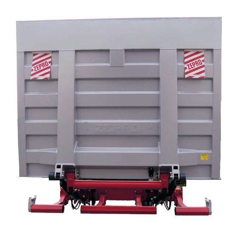
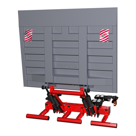
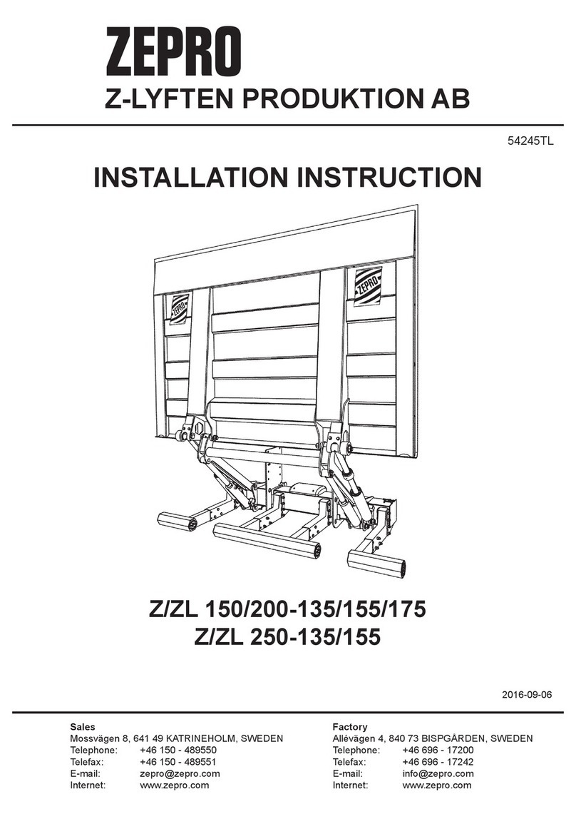
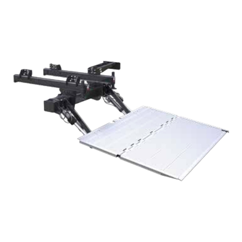
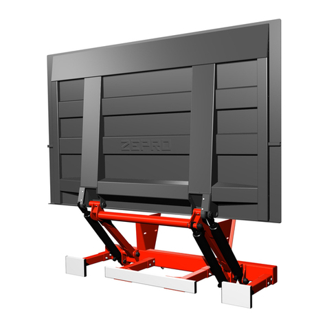
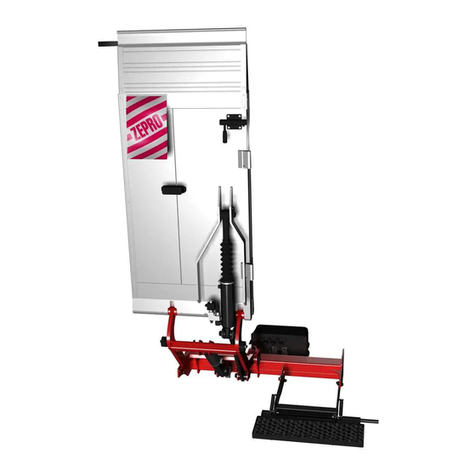
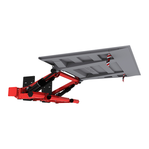
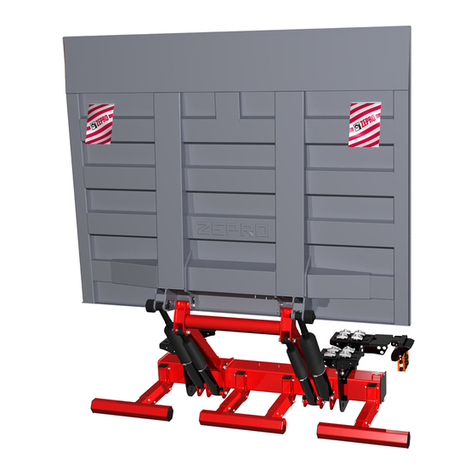
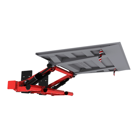
Zepro ZHZ 500-850 User manual

ZEPRO
Tel.: +46 (0)10-459 05 00
73161TL
2020-06-02
Installation Instruction
Tail Lift
ZHZ 500/600-850


Contents
3www.zepro.com
Contents
1 Introduction ..................................................................................................... 5
1.1 Important ................................................................................................ 5
1.2 CE marking ............................................................................................ 6
1.3 Hydraulicuid ......................................................................................... 6
1.4 Identication ........................................................................................... 7
2 Safety rules ....................................................................................................... 8
2.1 Repainting .............................................................................................. 8
2.2 Transport plug......................................................................................... 9
2.3 Moving parts – free movement ............................................................... 9
2.4 Attaching third-party equipment is prohibited ....................................... 10
2.5 Installation ............................................................................................ 10
3 Main parts ....................................................................................................... 10
4 Installation workflow...................................................................................... 11
4.1 Installing the support frame .................................................................. 11
4.2 Electrical connection............................................................................. 11
4.3 Installing the platform ........................................................................... 11
4.4 Installing cylinders ................................................................................ 11
4.5 Attaching decals ................................................................................... 11
5 Calculating the installed dimensions ........................................................... 12
5.1 C-dimension ........................................................................................ 12
5.2 D-dimension ........................................................................................ 12
5.3 H-dimension ......................................................................................... 12
6 Installation kits ............................................................................................... 13
7 Installation ...................................................................................................... 15
7.1 Installation of installation kit.................................................................. 15
7.2 Installing
the lift............................................................................ 50
7.3 Installing the Platform ........................................................................... 51
7.4 Installing the angle sensor.................................................................... 52
7.5 Installing the hydraulic unit ................................................................... 53
7.6 Control devices..................................................................................... 54
7.7 Connection box..................................................................................... 55
7.8 Control power cable.............................................................................. 56
7.9 Main power cable ................................................................................. 57
7.10 Installation of license plate light............................................................ 60
7.11 Installation of connection ramp............................................................. 61
7.12 Armstops .............................................................................................. 61
7.13 Platform stop ....................................................................................... 61
7.14 Adjustment of tilt cylinder...................................................................... 62
7.15 Purging the cylinders ............................................................................ 63
7.16 Transport lock ....................................................................................... 63

4
Contents
www.zepro.com
8 Electrical
and
hydraulic drawings................................................................. 64
8.1 ZHZ-600-850 MAConnection to circuit board....................................... 64
8.2 Connection to circuit board 4 – button operation.................................. 65
8.3 Connection of cab switch and alarm for open platform ........................ 66
8.4 Connection of control device ................................................................ 67
9 Markings and decals ...................................................................................... 68
9.1 Overview............................................................................................... 68
9.2 Load diagram........................................................................................ 69
9.3 Identicationplate............................................................................... 69
9.4 Work area ............................................................................................ 69
9.5 Driver’s instructions .............................................................................. 70
9.6 Danger area ......................................................................................... 70
9.7 Warning tape ....................................................................................... 70
9.8 Warningags....................................................................................... 71
9.9 CE marking........................................................................................... 71
10 Lubrication and fluid level check.................................................................. 72
10.1 Lubrication ............................................................................................ 72
10.2 Fluid level check ................................................................................... 72
11 Testing and verification ................................................................................. 73
11.1 Static test loading ................................................................................. 73
11.2 Dynamic test loading. ........................................................................... 74
11.3 Testing safety functions ........................................................................ 74
12 Dismantling..................................................................................................... 75
13 Specifications ................................................................................................ 76
13.1 Weights ................................................................................................ 76
13.2 Load centre........................................................................................... 77
13.3 Maximum power consumption –
Minimum recommended conductor cross sectional area................... 78
13.4 Maximum power consumption –
Minimum recommended conductor cross sectional area................... 79
13.5 Battery maintenance............................................................................. 79
13.7 Loading diagram ZHZ 500.................................................................... 80
13.6 Loading diagram ZHZ 600.................................................................... 80

Introduction
5www.zepro.com
1 Introduction
1.1 Important
The following “warning markings” appear in the installation instructions and are intended to draw
your attention to circumstances potentially causing unwanted situations, near misses, personal
injury or damage to the product, etc.
Take care.
Risk of damage to the product.
NOTE.
Take extra care. Risk of personal injury or damage to the product and the surroundings.
mWARNING!

6
Introduction
www.zepro.com
1.2 CE marking
Z-Lyften’s tail lifts on sale on the European market have been CE marked (CE stands for Conformité
Européenne) since 1 January 1995. The manufacturer guarantees that the product complies with
the EC Machinery Directive.
The aim of the EC Machinery Directive is to increase the safety of products throughout Europe.
There are some basic general rules that have to be following when installing Z-Lyften lifts.
Follow the installation instructions. If it is not possible to follow the installation instructions or if
modicationsarenecessary,themodicationshavetobeapprovedbythemanufacturer.Thisis
a consequence of CE marking regulations. The manufacturer is unable to certify compliance with
the Machinery Directive if the product is subsequently changed without its knowledge or approval.
To retain a valid CE marking for the product, it is essential to contact Z-Lyften.
Welding is not necessary except where recoended by the manufacturer.
To improve safety, we have enclosed decals for the lift that are easy to understand, regardless of
the language. Make sure these decals are attached so that the information they contain can be
seen by the lift operator.
Position control device so that it provides the operator with the safest possible working position,
as well as a clear view of the load, tail lift and working area. Follow the driver’s instruction manual
when using the control device and its functions.
1.3 Hydraulic uid
Our tail lift must work just as well in tropical heat as in the Arctic cold. The heat is no problem
fortheuid.Thecold,ontheotherhand,placesconsiderabledemandsonthehydraulicuid.
Zeprohasthereforeselectedhydraulicuidsthatcancopewithallofthesedemands.
1.3.1 Highly rened mineral oil (product no. 21963, 1 litre)
Contains zinc-free wear-preventing additives and provides extremely good wear protection.
Thehydraulicuid’sspeciallow-temperaturepropertiesandthehighviscosityindexmeanthat
the hydraulic system can be started in extreme cold, as well as delivering reliable operation in
uctuatingoperatingtemperatures.Theuidalsoprovidesthehydraulicsystemwithexcellent
protection against corrosion.
1.3.2 Biodegradable hydraulic uid (product no. 22235, 1 litre)
Asanoption,wealsooerabiodegradablehydraulicuid(environmentaluid)madeupofa
syntheticbaseoilcalledpolyalphaolen,whichisbiodegradable.Thebaseoildeliversoutstand-
ingpropertiesatlowandhightemperatures.Theuidremainsliquiddowntotemperaturesas
low as -50°C. Its oxidation stability is extremely good, resulting in a long service life with longer
changeintervalsasaresult.Theuidiseasytopumpthankstogoodlteringandairseparation
properties, together with a low density. This minimises the risk of cavitation and foaming. Con-
tact us for more information.
ATFuidorHFuidmaynotbeusedwithZ-Lyften.Theseuidsaecttherubberingaskets
and seals and shorten the service life.
NOTE!

Introduction
7www.zepro.com
1.4 Identication
Max. lifting capacity x 1 (kg)
Max. lifting height -850 = 850 mm
Cylinder model, MA = Double-acting adjustable tilt
Single-acting lift
Identication list E.g. - 600 - 850 MA
_ _ _ - _ _ _ - _ _ _ _ _

8
Safety rules
www.zepro.com
2 Safety rules
2.1 Repainting
Piston rods and cylinder covers must
not be painted. Painting these com-
ponents could damage the cylinder
seals.
Boots,
hydraulic hoses and cables
must not be painted/coated, as the
solvent in the paint could damage the
hoses/cablesandsignicantlyimpair
their durability.
NOTE.
Fig 1. Piston rods, cylinder covers and
boots must not be painted/coated
Fig 2. Hydraulic hoses must not be painted/coated
Fig 3. Cables must not be painted/coated

Safety rules
9www.zepro.com
2.2 Transport plug
When installing a lift, the transport
plug in the hydraulic unit must be re-
moved and replaced with the normal
tank cap supplied with the hydraulic
unit.
NOTE.
54
8
5
3
2.3 Moving parts – free move-
ment
During nal inspection*, the space
occupied by the moving cylinders
must be cleared and made safe.
There is a risk of collision between
cylinder and the following items:
subframe, truck chassis, member
for rear lights (number plate) and
the lift’s chassis bracket (with short
overhangs).
*Finalinspectionmustbeperformed
withtheplatformbythevehicleoor
and tilted down 10°. The clearance to
the nearest part of the cylinder must
be at least .40 mm
mWARNING!
The lift platform must not be tilted
down more than max. 10° from
horizontal when people are on the
platform.
mWARNING!
min. 40 mm
10°
10°
Fig 4. Replace the transport plug
with the normal tank cap
Fig 5. The clearance to the nearest part of
the cylinder must be at least 40 mm.
Fig 6. The lift platform must not be tilted down
more than max. 10° from horizontal.

10
Main parts
www.zepro.com
2.4 Attaching third-party equipment is prohibited
Third-party equipment (both electrical and hydraulic) must not be attached to Zepro’s tail lifts.
Attaching third-party equipment may interfere with the lift’s systems and its safety functions.
Risk of injury and damage. If it is necessary to install other equipment, check the vehicle
manufacturer’s body instructions and use the vehicle’s attachment features.
mWARNING!
2.5 Installation
The lift's platform must not be installed so that it cannot reach ground level.
Zepro’s tail lifts are only approved for installation with Zepro’s installation kits.
The lift’s capacity must NOT exceed the capacity approved by the vehicle manufacturer.
Take great care during test operation before adjusting the tilt cylinder to ensure that the vehicle
body is not damaged. Make sure that the tilt cylinder is adjusted in such a way that the platform
does not catch on the vehicle body when the platform is tilted up fully.
mWARNING!
3 Main parts
Platform
Tilt cylinder
Lift arm
Support arm
Frame
Lift cylinder
Link
Step
Fig 7. Overview

Installationworkow
11www.zepro.com
4 Installation workow
4.1 Installing the support frame
• Install the installation kit
• Install the lift chassis
• Install the hydraulic unit
• Install the hydraulic hoses
• Add hydraulic oil in the hydraulic oil tank
4.2 Electrical connection
• Install the control devices
• Install the control devices’ cables
• Install the main power cable
4.3 Installing the platform
• Install the platform
• Test functions and installation
4.4 Installing cylinders
• Adjusting tilt cylinder
• Install the connecting ramp
• Test operation
4.5 Attaching decals

12
Calculating the installed dimensions
www.zepro.com
5 Calculating the installed dimensions
For easier installation, it is useful to calculate and specify the necessary dimensions in advance.
DeterminetheC-dimensionrst,thenobtaintheotherdimensionsfromtherelevanttable.You
shouldtrytopositiontheliftashighaspossiblewithinthespeciedC-dimensioninthetable.
5.1 C-dimension
TheC-dimensionisthedistancebetweenthetopthesupportframeandthevehicleoorlevel.
This dimension governs how far the lift needs to be installed under the vehicle body (D-dimension)
andthespacebetweentheliftarmsintheupperpositionandthevehicleoorlevel(A-dimension).
5.2 D-dimension
The D-dimension is the space that the lift needs, measured from the rear edge of the body to the
front edge of the support frame (in the direction of the vehicle). Once the C-dimension has been
determined, the D-dimension can be obtained from the table.
5.3 H-dimension
TheH-dimensionistheheightfromground(unloaded)tothevehicleoorlevel.TheH-dimension
must not be greater than the lift’s maximum lifting height. The lift’s platform must always be able
to reach ground level.
H = B+C
B max. 400
297
C
D
C D
450 557
400 597
350 629
300 640
250 674
200 688
150 698

Installation kits
13www.zepro.com
6 Installation kits
Make Model Version Other Tot. weight Part.no. Section
Fiat
Peugot
Citroen
Ducato
Boxer
Jumper
2007- L= 3000, 3450, 4035
X= 1015
24.1 kg 72807TL 7.1.1
Fiat
Peugot
Citroen
Ducato
Boxer
Jumper
2007- L= 4035
X= 1380
24.1 kg 76013TL 7.1.1
Ford Transit 2006-2013 L= 3300, 3750
X= 997
12.7 kg 73029TL 7.1.2
Ford Transit Jumbo
FWD
2014- 10.2 kg 74914TL 7.1.3
Ford Transit Jumbo
RWD/4x4
2014- 10.2 kg 75018TL 7.1.4
Mercedes
Mercedes
Mercedes
Mercedes
VW
VW
VW
Sprinter
Sprinter
Sprinter
Sprinter
Crafter
Crafter
Crafter
2018-
2006-2017
2006-2017
2006-2017
2006-2016
2006-2016
2006-2016
3,5t RWD, L= 4325
3,5t och 5t RWD, L= 4325, Vehicle lenght= 7367
3,5t RWD, L= 4325, Vehicle lenght= 6945
3,5t och 5t RWD, L=4325, Vehicle lenght= 7345
3,5t och 5t RWD, L= 4325, Vehicle lenght= 7367
3,5t RWD, L= 4325, Vehicle lenght= 6945
3,5t och 5t RWD, L= 4325, Vehicle lenght= 7345
14 kg 73169TL 7.1.5
Mercedes Sprinter 2018- 3,5t RWD, L= 3665 24.9 kg 73167TL 7.1.6
Mercedes Sprinter 2018- 5t RWD, L= 4325, Vehicle lenght= 6967 17.6 kg 76796TL 7.1.7
Mercedes Sprinter 2006-2016 5t RWD, L= 4325, Vehicle lenght= 6945
VW Crafter 2006-2017 5t RWD, L= 4325, Vehicle lenght= 6945
Mercedes Sprinter 2018- 5t RWD, L=3665 24.5 kg 76801TL 7.1.8
Mercedes Sprinter 2016-2017 5t RWD, L=3665
VW Crafter 2016-2016 5t RWD, L=3665
VW Crafter 2017- FWD 13.7 kg 76745TL 7.1.9
VW Crafter 2017- RWD/4x4 14.6 kg 77132TL 7.1.10
Renault
Opel
Nissan
Master
Movano
Interstar
1997- 2010 FWD 12.7 kg 74451TL 7.1.11
Renault
Opel
Nissan
Master
Movano
NV 400
2010- FWD 18.1 kg 74452TL 7.1.12
Renault
Opel
Nissan
Master
Movano
NV 400
2010- RWD 29.1 kg 75236TL 7.1.13
Mercedes
Mercedes
VW
Sprinter
Sprinter
Sprinter
2018-
2006-2017
2006-2016
5t RWD, L= 4325, Vehicle lenght= 6967
5t RWD, L= 4325, Vehicle lenght= 6945
17,6 Kg 76796TL 7.1.14
Mercedes
Mercedes
VW
Sprinter
Sprinter
Crafter
2018-
2016-2017
2016-2016
5t RWD, L=3665
5t RWD, L=3665
5t RWD, L=3665
24,5 Kg 76801TL 7.1.15
VW Crafter 2017- 3,5t RWD 14 kg 77132TL 7.1.16

14
Installation kits
www.zepro.com
Make Model Version Other Tot. weight Part.no. Section
Mercedes Sprinter 2018- 3,5t RWD, L= 4325, Vehicle lenght= 6967 12,5 Kg 77833TL 7.1.17
Mercedes Sprinter 2018- FWD 15,5 Kg 78012TL 7.1.18
Mercedes Sprinter 2018- 5t RWD, L= 4325 15,2 Kg 78128TL 7.1.19
Mercedes Sprinter 2018- 3,5t RWD, L= 3665 26, 8 kg 78130TL 7.1.20
Mercedes Sprinter 2018- 3,5t RWD, L= 4325 15,2 Kg 78160TL 7.1.21
Iveco Daily 2014 L=3520 11,7 kg 77523TL 7.1.22
Iveco Daily 2014 L= 4100 12,5 kg 78229TL 7.1.23
L= wheelbase
X= rear overhang
FWD= front wheel drive
RWD= rear wheel drive
AWD= four wheel drive

Installation
15www.zepro.com
7 Installation
7.1 Installation of installation kit
7.1.1 Fiat Ducato, Peugot Boxer,
Citroen Jumper (part. no.
72807TL) Models from 2007
1 Dismantle the spare wheel and as-
sociated mounts and any ladder.
The spare wheel is then placed in
the vehicle body.
There is no space for the spare
wheel under the vehicle after
installation of the lift.
NOTE.
2 Grind away the welded screw from
the lower mount on the bumper
brackets. See Fig 8. If necessary,
drill a Ø11 hole through the vehicle’s
bracket for a through M10 screw.
Use a 20 mm spacer during installa-
tion.Applyrustproongagent.
3 Install the chassis bracket without
tightening. Installation play between
chassis bracket and the lift’s dimen-
sions (997 mm) may not exceed 2
mm.
4 When installing a folding platform,
slide the chassis bracket 20 mm to
thelefttoavoidconictwiththerear
door. See Fig 9.
If the lift is installed symmetrically,
the spacers 14+6 mm are not re-
quired (normal platform).
NOTE.
5 Install the lift without tightening the
screws. Use 3 x M12x35 screws to
the right of the cut-out in the chassis
bracket and 2 x M12x35 screws to
the left of the cut-out. See Fig 10.
Fig 8. Grind away the welded screw
Fig 9. When installing a folding plat-
form, slide the chassis bracket 20 to the
left to avoid conflict with the rear door.
Fig 10. Install the lift without tightening. Use
3 x M12x35 screws to the right of the cut-
out in the chassis bracket and 2 x M12x35
screws to the left of the cut-out.

16
Installation
www.zepro.com
6 Use the adjusting screws to adjust
the armstop so that the distance
between the centre of the lift arm’s
shaftholeandtheoorofthebody
approx. 25 mm. See Fig 11.
5 x M12x35 screws
5 x M12 M6MF nuts
Tightening torque: 80 Nm
(25)
Adjusting screw for armstop.
Fig 11. Adjust the height difference between
the lift arm and the floor of the body to ap-
prox. 25 mm. Then adjust the lift so it is as
close to the rear doors as possible.
Fig 12. Adjust the lift so it is as close
to the rear doors as possible.
Fig 13. Overview.
Adjust
7 Adjust the lift so it is as close to the
rear doors as possible. Tighten all
the screws and nuts using a torque
wrench, see Fig 12.
Tightening torque 80 Nm.
8 Install the platform and cylinder
between link and platform see "7.3
Installing the Platform" on page
51
.

Installation
17www.zepro.com
A
A
1 x M16x40 screw
1 x M16 clip
1 x Square washer
Tightening torque: 180 Nm
2 x M10x1.25 screws L = 55
1 x Washer
1 x Spacer 20 mm
Tightening torque: 50 Nm
1 x M10x70 screw
1 x Washer
1 x M10 nyloc nut
1 x Spacer 20 mm
Tightening torque: 50 Nm
1 x M14x1.5 screw L = 30
1 x Square washer
Tightening torque: 120 Nm
2 x M10x85 screws
1 x Washer
1 x M10 nyloc nut
Tightening torque:50 Nm
2 x M12x35 screws
1 x Washer
1 x M12 nyloc nut
1 x spacer 6 mm
Tightening torque: 80 Nm
2 x M12x50 screws Washer
1 x M12 nyloc nut
1 x Spacers 14+6 mm
Tightening torque: 80 Nm
Fig 14. Overview, diagonally from below

18
Installation
www.zepro.com
7.1.1.1 Assembly 72807TL
Åtdragningsmoment för skruv och mutter:
Tightening torque for screws and nuts:
- M10...... 50Nm.
- M12...... 80Nm.
- M14...... 120Nm.
- M16...... 180Nm.
* Monteringssats för Fiat Ducato skall monteras förskjuten 14-20 mm åt vänster för
att unvika konflikt mellan bakdörrar och bryggas gångjärn.
** Om lyften monteras symetriskt, båda fästprofiler (pos.3 och 4) monteras
utvändigt på pos 2 resp. pos.1). Pos 18 & pos 22 (distans 14 mm+6mm) utgår.
*** Montagespel mellan lyftens infästningsrör (utvändigt mått, 997mm) skall inte
vara större än 2 mm sammanlagt.
This drawing is property of Z-Lyften Produktion AB and is loaned subject to return upon demand. It is not
to be reproduced or used directly or indirectly in any way detrimental to the interest of Z-Lyften Produktion AB.
Z51795.73742TLDistans 6 mm/ Distance 6 mm222
ISO 7043 - M1221980TLMutter M6MF M12 Loc-king/ Nut M121021
8ISO 4014 - M10 x 7022248TLSexkantskruv/ Hexagon head screw220
8ISO 4017 - M12 x 5022295TLSexkantskruv / Hexagon head screw219
Z5040872798TLDistans 14 mm/ Distance 14 mm118
1DIN 931-1 - M10 x 8521747TL
Sexkantskruv/ Hexagon head screw
417
AZ5040672796TL
Fyrkantsbricka/ Square washer
416
Z5040572795TL
Fäste M16/ Bracket M16
215
ISO 8676 - M14 x 1,5 x 30 - A
21191TL
Sexkantskruv/ Hexagon head screw
214
5
ISO 7089 - 10 - 140 HV20184TLBricka/ Plain washer813
8DIN 960 - M10 x 55 x 1,2522765TLSexkantskruv fingängad/ Hexagon head screw
4
12
Z5040472794TLDistans 20 mm/ Distance 20 mm611
1DIN 125 - A 1320181TLBricka/ Plain washer410
1DIN 985 - M1020170TLSexkantsmutter/ Hex Nut69
1DIN 985 - M1221664TLSexkantsmutter M12 Loc-king/ Hex Nut48
5
ISO 4017 - M12 x 3521311TLSexkantskruv/ Hexagon head screw 12
7
1ISO 4017 - M16 x 4021829TLSexkantskruv/ Hexagon headed screw26
AZ5040372793TLFörstärknigsprofil/ Reinforcement beam15
AZ50409-272800TL
Fästprofil-vänster/ Bracket-left
14
AZ50409-172799TL
Fästprofil-höger/ Bracket-right
13
CZ5041472806TLMonteringsfäste, vänster sida/ Mounting bracket,left side12
CZ5041372805TLMonteringsfäste, höger sida/ Mounting bracket, right side11
Rev.Drawing nr.Stock nr.Title/DescriptionQtyItem
Drawing interpretation unless otherwise
specified. All measures intends finished product
Title
Material
Dimension
Date
Weight (kg)
Scale
Designer Checked by Approved by
Stock nr.
Drawing nr.
Sheet
Size
Revision
IS0 tolerances and drawing rules
Tolerance:
Surface finish:
Welding:
Mont.sats ZHZ, Fiat Ducato
ZHZ 600
-
2012-10-22 BC 1 : 10PSBC
24,1
Z50415 D
72807TL
A3
1
/
1
-
Z-Lyften Produktion AB
Drawn
BC
A CARGOTEC BRAND
Used on:
Mount.kit ZHZ, Fiat Ducato ZHZ 600
Z
Z
E
E
P
P
R
R
O
O
1250
1000
***
1250
464,5
20
500
***
16 14
17
2
15
16
6
4795
**1810819
11
6
16
15
1
14
16
3
12
20
21
7
A
B
Rev.Tag Date Rev. number Revised ECR Approved
A 2013-04-25 6795 PS 74 CL
B 2013-11-25 6902 TC 167 CL
B
B
B
B
B
**22
B
B
B
13
B
C2014-03-10 6962 NS 184 CL
C
C
C
C
D2016-08-11 7297 BC 787 PS

Installation
19www.zepro.com
7.1.1.2 Assembly 76013TL
Åtdragningsmoment för skruv och mutter:
Tightening torque for screws and nuts:
- M10...... 50Nm.
- M12...... 80Nm.
- M14...... 120Nm.
- M16...... 180Nm.
* Monteringssats för Fiat Ducato skall monteras förskjuten 14-20 mm åt vänster för
att unvika konflikt mellan bakdörrar och bryggas gångjärn.
** Om lyften monteras symetriskt, båda fästprofiler (pos.3 och 4) monteras
utvändigt på pos 2 resp. pos.1). Pos 18 & pos 22 (distans 14 mm+6mm) utgår.
*** Montagespel mellan lyftens infästningsrör (utvändigt mått, 997mm) skall inte
vara större än 2 mm sammanlagt.
This drawing is property of Z-Lyften Produktion AB and is loaned subject to return upon demand. It is not
to be reproduced or used directly or indirectly in any way detrimental to the interest of Z-Lyften Produktion AB.
Z51795.73742TLDistans 6 mm/ Distance 6 mm222
ISO 7043 - M1221980TLMutter M6MF M12 Loc-king/ Nut M121021
8ISO 4014 - M10 x 7022248TLSexkantskruv/ Hexagon head screw220
8ISO 4017 - M12 x 5022295TLSexkantskruv / Hexagon head screw219
Z5040872798TLDistans 14 mm/ Distance 14 mm118
1DIN 931-1 - M10 x 8521747TL
Sexkantskruv/ Hexagon head screw
417
AZ5040672796TL
Fyrkantsbricka/ Square washer
416
Z5040572795TL
Fäste M16/ Bracket M16
215
ISO 8676 - M14 x 1,5 x 30 - A
21191TL
Sexkantskruv/ Hexagon head screw
214
5
ISO 7089 - 10 - 140 HV20184TLBricka/ Plain washer813
8DIN 960 - M10 x 55 x 1,2522765TLSexkantskruv fingängad/ Hexagon head screw
4
12
Z5040472794TLDistans 20 mm/ Distance 20 mm611
1DIN 125 - A 1320181TLBricka/ Plain washer410
1DIN 985 - M1020170TLSexkantsmutter/ Hex Nut69
1DIN 985 - M1221664TLSexkantsmutter M12 Loc-king/ Hex Nut48
5
ISO 4017 - M12 x 3521311TLSexkantskruv/ Hexagon head screw 12
7
1ISO 4017 - M16 x 4021829TLSexkantskruv/ Hexagon headed screw26
AZ5040372793TLFörstärknigsprofil/ Reinforcement beam15
AZ50409-272800TL
Fästprofil-vänster/ Bracket-left
14
AZ50409-172799TL
Fästprofil-höger/ Bracket-right
13
Z5389776012TLMonteringsfäste ZHZ -V/ Mounting bracket ZHZ- L12
Z5389676011TLMonteringsfäste ZHZ - H/ Mounting bracket ZHZ - R11
Rev.Drawing nr.Stock nr.Title/DescriptionQtyItem
Drawing interpretation unless otherwise
specified. All measures intends finished product
Title
Material
Dimension
Date
Weight (kg)
Scale
Designer Checked by Approved by
Stock nr.
Drawing nr.
Sheet
Size
Revision
IS0 tolerances and drawing rules
Tolerance:
Surface finish:
Welding:
Mont.sats ZHZ, Fiat Ducato L4
ZHZ 600, Fiat Ducato L4
-
2016-11-10 BC 1 : 10PSBC
24,1
Z53898
76013TL
A3
1
/
1
-
Z-Lyften Produktion AB
Drawn
BC
A CARGOTEC BRAND
Used on:
Mount.kit ZHZ, Fiat Ducato L4 ZHZ 600, Fiat Ducate L4
1250
1000
***
1250
824
20
500
***
16 14
17
215
16
6
47
95
**1810819
11
6
16
15
1
14
16
3
12
20
21
7
**22
13

20
Installation
www.zepro.com
7.1.2 Ford Transit (part no. 73029TL)
Models from 2006
1 Dismantle the spare wheel and as-
sociated mounts and any ladder.
The spare wheel is then placed in
the vehicle body.
There is no space for the spare
wheel under the vehicle after
installation of the lift.
NOTE.
2 Dismantle the mounting brackets
holding the bumper. These are
installed with 4 screws, which will
be replaced in point 4. Remove the
towing eyelet and its nuts. Treat the
brackets afterwards with rustproof-
ing agent.
3 Check that the supplied spacer
tubestintheframe.Ifnecessary,
drill the holes to Ø 20.5 so that the
spacers can be installed. Apply
rustproongagent.SeeFig 15.
4 Install the chassis brackets and the
bumper brackets with the supplied
5 x M12x110 screws, M12 nyloc
nuts and washers. Tighten with the
aid of a torque wrench. See Fig 15.
Tightening torque 80 Nm
5 Install the lift, see "7.2 Installing the
lift" on page 50.
6 Install the platform, see "7.3 Install-
ing the Platform" on page 51.
5 x M12x110 screws
5 x M12 nyloc nuts
10 x Washers
Tightening torque: 80 Nm
1 x Washer plate
2 x Spacer tubes
Fig 15. Installation of chassis brack-
ets and bumper brackets.
This manual suits for next models
1
Table of contents
Other Zepro Lifting System manuals

Zepro
Zepro Z 10 User manual

Zepro
Zepro ZN 2500-130 User manual

Zepro
Zepro Z 150-135 User manual

Zepro
Zepro Z 2500-130 Series User manual

Zepro
Zepro ZHZ 500 User manual

Zepro
Zepro Z 2500-130 User manual

Zepro
Zepro ZHD 1500 Original operating manual

Zepro
Zepro 78826TL User manual

Zepro
Zepro ZHD 2500-130 User manual

Zepro
Zepro ZHD-1500-MA-DA User manual