– 8 –
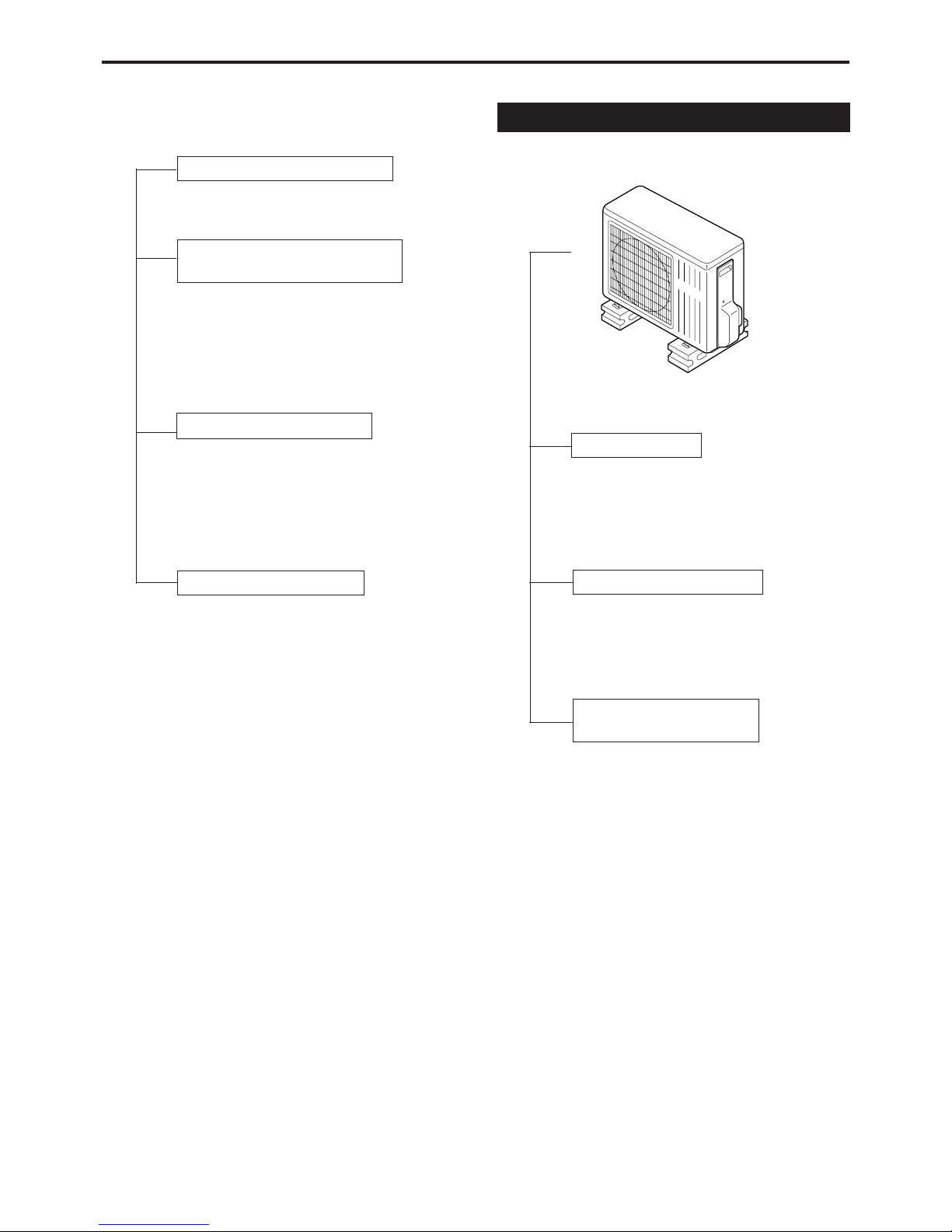
OUTDOOR UNIT
Inverter control
Inverter control reduce the ON/OF times
of compressor,so can keep the room
temperature changeless during
operation.
Electricity consumption
Inverter control can operate with less
electricity consumption than normal air
conditioner.
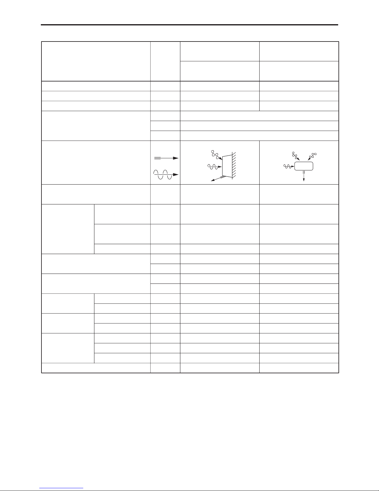
Deice(Defrost) control
(for outdoor unit panel)
Deice operation automatically starts
when the outdoor temperature is lower
than 2℃and the ice is formed on the
bottom of outdoor unit.
Hot-start control (heating)
The indoor fan stops until the evaporator
piping temperature will be reached.
Anti-freezing control for the
evaporator
Compressor will be stopped when the
evapolator’s piping temperature is below
2℃for one minute.
Compressor will be restarted when the
evaporator’s piping temperature is above
2℃.
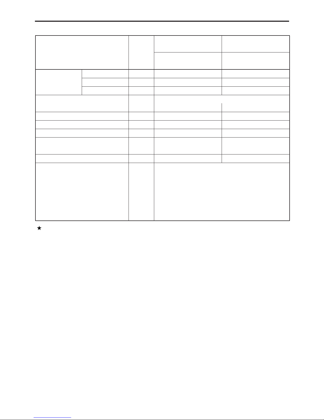
Airflow direction control
Automatic airflow direction control
The louver automatically swings up and
down (cooling, dry)...horizontal and 35°
downward.
The louver is set at 70°downward
during heating operation.
Auto recovery function
If there is any power failure during
operation, operation status before power
failure is memorized.
3〜4 minutes after power recovery, the
unit restarts automatically with previous
operation status memorized.
(3〜4 minutes is protective time for
compressor.)
Attention
Because of Auto recovery function, if
shutting off the power supply during
operation, the unit may restart
irrespective your intention when turning
on the power supply next time.
If the unit is not to be used for a long
time, shut off the power supply after
terminating all operation with remote
controller.
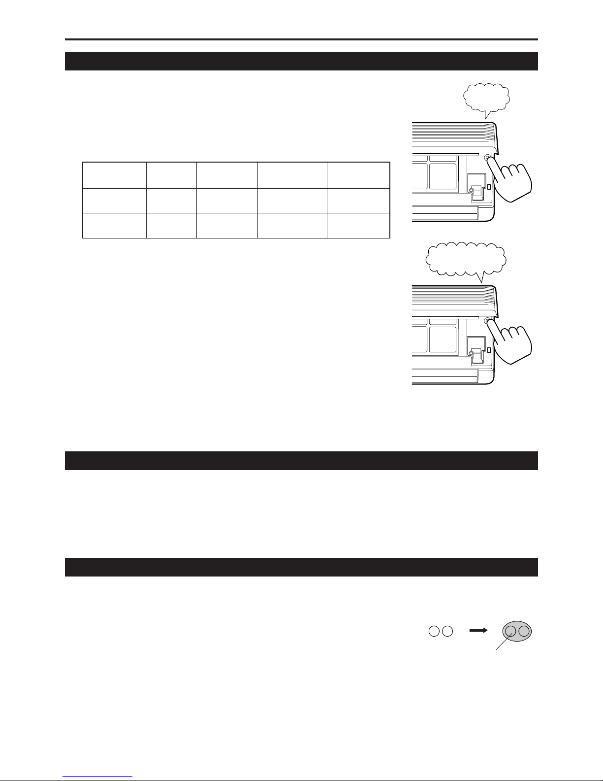
FUNCTIONS


 null")