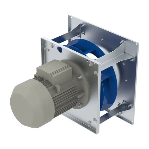
4.5.2 Erecting the equipment: Design ER...-..N... / ER...-..K... / GR...
19
4.5.3 Optimal installation distances according to for RH../ ER../ GR..
fans . . . . . . . . . . . . . . . . . . . . . . . . . . . . . . . . . . . . . . . 19
4.6 Mounting of motors . . . . . . . . . . . . . . . . . . . . . . . . . . . . . . . . . . . 20
4.7 Outdoor fans in a humid atmosphere . . . . . . . . . . . . . . . . . . . . . 20
4.8 Motorheating . . . . . . . . . . . . . . . . . . . . . . . . . . . . . . . . . . . . . . . 21
5 Electrical installation . . . . . . . . . . . . . . . . . . . . . . . . . . . . . . . . . . . . . . 21
5.1 Safety precautions . . . . . . . . . . . . . . . . . . . . . . . . . . . . . . . . . . . 21
5.2 Connection . . . . . . . . . . . . . . . . . . . . . . . . . . . . . . . . . . . . . . . . . 21
5.2.1 Motor size “D” and “G” .......................... 22
5.2.2 UL: note for cable entrances . . . . . . . . . . . . . . . . . . . . . . 23
5.3 EMC-compatible installation of control lines . . . . . . . . . . . . . . . . 23
5.4 Mains connection . . . . . . . . . . . . . . . . . . . . . . . . . . . . . . . . . . . . 23
5.4.1 Line voltage for 1~ types . . . . . . . . . . . . . . . . . . . . . . . . . 23
5.4.2 Line voltage for 3~ types . . . . . . . . . . . . . . . . . . . . . . . . . 24
5.4.3 Required quality attributes for the mains voltage . . . . . . . . . 24
5.4.4 Operating in IT-System . . . . . . . . . . . . . . . . . . . . . . . . . . 24
5.4.5 UL: Short-circuit protection for branch circuits (UL508C) . . . 25
5.5 Residual-current-operated protective device . . . . . . . . . . . . . . . . 25
5.6 Motor protection . . . . . . . . . . . . . . . . . . . . . . . . . . . . . . . . . . . . . 25
5.7 Analog input (0...10 V) for setting fan speed . . . . . . . . . . . . . . . 25
5.8 Output voltage +10 V . . . . . . . . . . . . . . . . . . . . . . . . . . . . . . . . . 27
5.9 Voltage supply for external devices, only motor sizes “D”, “G”
(+24 V, GND) . . . . . . . . . . . . . . . . . . . . . . . . . . . . . . . . . . . . . . 27
5.10 Enable, device ON / OFF (Digital In 1 D1) . . . . . . . . . . . . . . . 28
5.11 Relay output (K1) . . . . . . . . . . . . . . . . . . . . . . . . . . . . . . . . . . . . 28
5.12 Potential at control voltage connections . . . . . . . . . . . . . . . . . . . 28
5.13 Add-on modules . . . . . . . . . . . . . . . . . . . . . . . . . . . . . . . . . . . . . 28
6 Start-up . . . . . . . . . . . . . . . . . . . . . . . . . . . . . . . . . . . . . . . . . . . . . . . . 30
6.1 Prerequisites for commissioning . . . . . . . . . . . . . . . . . . . . . . . . . 30
7 Diagnostics / Faults . . . . . . . . . . . . . . . . . . . . . . . . . . . . . . . . . . . . . . . 31
7.1 Trouble shooting . . . . . . . . . . . . . . . . . . . . . . . . . . . . . . . . . . . . . 31
7.2 Status Out with flash code . . . . . . . . . . . . . . . . . . . . . . . . . . . . 32
7.3 Behaviour in rotation by air current in reverse direction . . . . . . . 34
8 Service work . . . . . . . . . . . . . . . . . . . . . . . . . . . . . . . . . . . . . . . . . . . . . 35
8.1 Repairs / maintenance . . . . . . . . . . . . . . . . . . . . . . . . . . . . . . . . 35
Assembly instructions ECblue
L-BAL-F046-GB 1203 Index 003 Part.-No. 00297758-GB
3/45
